Please review the site Rules, Terms of Service, and Privacy Policy at your convenience. Rules, TOS, Privacy
Get familiar with the reaction system: Introducing the Reaction System

circuit design issue / question

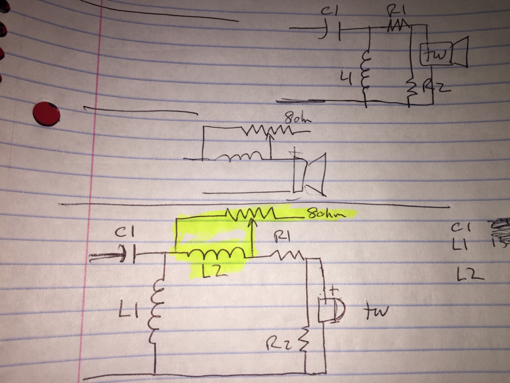
I’m considering adding a circuit to address a slight upward tilt of a tweeter by using a varying resistor (1/2 Lpad set-up) across a small inductor (as sometimes used with full range drivers) in the HP filter section of a two-way (the yellow section in the attached pic.).

I understand Lpads have more generally been used to adjust the (entire) level of the tweeter in relation to the mid (or woofer) i.e. JBLs.  However (even while keeping the load consistent) adjusting upward or downward the tweeter level in this fashion upsets the HP filter relationship to the LP filter (moving the whole tweeter curve up or down, creating a void or hump across this crossover range). 

In comparison, implementing a varying resistor across an inductor can be designed to vary the tweeter’s tilt (from a targeted frequency point) with less or nominal impact on the HP / LP relationship.  

My question is will this set-up, which places an inductor in ~series with a capacitor (C1 relative to L2, be problematic?  And/or does the inductor L1 in parallel (dropping between the cap and coil) relieve this issue? Or is this a non-issue?  I’d like to put this into passive crossover designer to confirm, but running 'parallels' on my older MAC wasn’t all that successful.

Thanks.  
«1

Comments

  • So you want a R-L contour circuit to roll off the rising tweeter response, right?  PCD has a "Textbook R-L Contour" calculator that will get you in the ballpark.  The L value (calculated by PCD based on the entered Fmin and Fmax values) essentially sets where the roll off occurs and the entered R value sets the depth of roll off.  You'll also need an estimate of the tweeter's impedance at the R-L's middle frequency with the L-pad in place.  PCD unfortunately won't let you sim both the R-L contour circuit and the L-pad because it uses fixed circuit topologies.  You can use XSim or some other simulation program for that.

    The impact of the R-L circuit has on the remainder of the crossover (C1/L1) is hard to estimate without throwing it in a simulation.  But I would think that if the R-L frequency is far enough away (e.g.10 KHz) from the crossover frequency (e.g. 2 KHz) it shouldn't have a major effect.  That's just a seat of the pants guess though. 


    jr@mactajanes
  • edited March 2020
    I'd lose R2 and the RL contour put a resistor in series with C1 to adjust the "tilt".  I'm not a big fan of rolling off the tweeter top end because of the negative effect on the off axis
    JasonP
     John H, btw forum has decided I don't get emails
  • Thx for all the input !

    I'm playing with the +'s and -'s of having an adjustable tweeter level, and find a tilt adjustment more valid than the 'std' Lpad on the tweeter (which as mentioned above negatively affects the crossover frequency zone response).  

    I bi-amp and use active crossover DSP between the woofers and the mid/tw, and passive components for the mid/tw crossover.  And as such I can set the tweeter response with a slight hot tilt so that in using the L-R contour (thx Ed) I can hone in / tune, via the adjustable L-R, where it sounds best in my listening room, and as measured off axis.   And John I think it was you whom suggested setting/measuring Xover at 15 degrees off axis, which is now part of my process- thx.


  • Use the DSP for this.
    I'm not deaf, I'm just not listening.
  • edited March 2020
    Yes, probably the best solution. I just like the idea of a knob...  or maybe a toggle, or both (my tube buffer/pre I put 'btwn my amp for the mid/highs.  The toggel adjusts, nominally, the pre-tube voltage)
  • jhollander

    I had worked out a 3rd order HP for the tweeter (with the two resistor attenuation circuit), to a good point.

    However, per your recommendation I'm dumping the RL idea, and have a quesiton of dumping R2 (having a single series resistor?) 

    Not having access to a full crossover software designer (just the calculators), I’d appreciate your thoughts on the value of a series resistor (as a staring point), and best location within the HP filter for the series resistor.  I.e. upstream from the filter.  Or possibly downstream from the filter, and as such making an adjustment to the tweeter’s resistance value (the tweeter + the R) in the calculator?. 

    The beyma mid sensitivity is stated to be 92.5 dB and the tweeter at 102dB (both rated 1w / 1m).  

    thanks


  • edited March 2020
    This is the same issue that Joey is going through. Design an x-o with some traced curves.  So I'll step through how I would do this.  First up what is the size of the baffle and where is the driver located on the baffle?  Second, do you have the traced curves?
     John H, btw forum has decided I don't get emails
  • edited March 2020


  • Ok I traced them myself as I need the impedance curves. I used FPGraphTracer.  Next stop the Blender
     John H, btw forum has decided I don't get emails
  • edited March 2020
    jhollander
    THX, Hope to limit your efforts (which I certainly appreciate) to how to best set the series resistor value (to deal with sensitivity diff of drivers), and location in the filter chain.

    https://www.beyma.com/speakers/Fichas_Tecnicas/beyma-altavoces-hoja-tecnica-coaxial-5CX200NdN.pdf

  • Here is adding the baffle to the woofer/ mid.  I did not show extracting min ph in the control tab


     John H, btw forum has decided I don't get emails
  • Here is adding the baffle to the tweeter


     John H, btw forum has decided I don't get emails
  • edited March 2020
    for what its worth, this is where I was at, with the 3ohmR1 and 5ohm R2 atten resistors, 2nd LP, 3rd HP (both BW) 18in 15 deg


  • The beyma impedance file only goes to 10K so I'm going to try to fix it in response modeler
     John H, btw forum has decided I don't get emails
  • Looks like my trace of the tweeter is also wrong...
    dcibel
     John H, btw forum has decided I don't get emails
  • edited March 2020
    I just started by having q re your recommendation; affect of having one series R to adjust driver sensitivities and where to put it in the filter layout (upfront or at the tw)  i.e. any thoughts of if I put say a 2ohm R just in front of the tw (I can then model Xover for total tw res (tw+2) how this may drop its relative level (or does this muck up / tilt the tw), or is it just best to place R before the HP filter

    Thanks just doesn't seem to do it.  
  • Other than being rusty, I get a kick out of this.  Here's the base FR with the baffle added to both.

     John H, btw forum has decided I don't get emails
  • Here's a quick x-o.  Without measuring it's a bit of a crap shoot. Bonus is with a coax not much offset to worry about and because the FRs were on the same graph the spl match should be good. The bad is no box info so the bass match could be off.  The 4.5 mH inductor should be big enough for full baffle step in spite of the FR curve. Other bad is the bumps in the higher frequencies may not be real a few degrees off axis.  If anyone wants the XSim file PM me your email.

     John H, btw forum has decided I don't get emails
  • cool, thanks
    so a 2nd order HP, where if you don't mind me asking would you expect the Xover freq?
  • Ha, way to low...I didn't check...this one is at 3.8K


     John H, btw forum has decided I don't get emails

  •  John H, btw forum has decided I don't get emails
  • That looks great.  I luv the smell of a freshly designed Xover in the am with my coffee...
    THX
  • edited March 2020
    one last what if, if I may..
    what would targeting 5.4K Xover look like (values)? I've had a preference, if the driver(s) can work (I measure the off axis roll) for getting the Xover just out of the 1-5KHz (highest hearing sensitivity range)
    And you may have nailed it on the 3.8K, looking at the fall off of the mid driver...
  • Here's the raw drivers on baffle. It's not going above 4K without a lot of parts.  Really unless you measure it's not the best idea to notch or contour suspect FR graphs.


     John H, btw forum has decided I don't get emails
  • edited March 2020

    While the XSim does appear shifted downward ~2800 Hz from the co’s sheet, 3.8K looks to be a really good Xover target (and great advice to dump the RL on this)

    THX

  • Here's the raw drivers on baffle. It's not going above 4K without a lot of parts.  Really unless you measure it's not the best idea to notch or contour suspect FR graphs.

    .
    Have another look at the x-axis on the datasheet.


    I'm not deaf, I'm just not listening.
  • edited March 2020
    I'm looking at the mid driver roll off at 8g on the co's sheet (blue trace) seems to be at 5.2g (black trace) on XSim ? @ 95 X-axis
  • Hmm may have messed up that trace. I'll try it again
     John H, btw forum has decided I don't get emails
  • edited March 2020
    same with the tw? check dips at 2.5g vs ~1g on XSim 
  • Log scale wins again.  I'll have something better in a few minutes...
     John H, btw forum has decided I don't get emails
Sign In or Register to comment.