Site Links
Howdy, Stranger!
It looks like you're new here. If you want to get involved, click one of these buttons!
Quick Links
Categories
Who's Online (0)
Setting up for electronics and amp testing, AMP with dummy load
Ok, part two, continuing from here https://diy.midwestaudio.club/discussion/1458/setting-up-for-electronics-and-amp-testing-asus-xonar-u7-usb-audio.
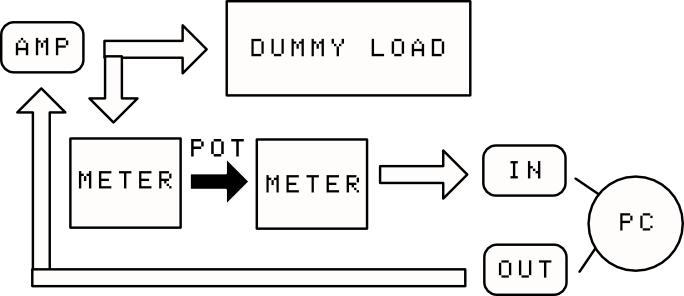
Here is a block diagram of the basic idea, which I think is just normal and solid:

The Xonar U7 handles IN and OUT from the PC, feeds the amp directly (though maybe I'll need a step up clean pre-amp, but I don't think so). It gets it's input back from a simple log POT that'll bring output voltage at test down to about 1.5V or such (won't know until I test). To make all this easier, there two two microcontoller based True RMS meters. One meter (first) reads the actual output voltage of the amp, and the second the stepped down voltage after the POT.
Digging in deeper, first Dummy Load setup.
I have ohmite 100 watt wirewound resistors as so: 2x 8 ohm, 2x 4 ohm, 2x 3 ohm. I'll have 8 ohms: 2x4 in series, 6 ohms: 2x3 in series, and 4 ohms: 2x8 in parallel. I have three heavy duty rocker SPST switches to connect/disconnect each leg. All the resistors will go on this 0.85C/watt heatsink: https://heatsinkusa.com/12-000-wide-extruded-aluminum-heatsink/ - 12 " wide, 3" long version. I've put the resistors onto the sink with thermal adhesive.
Deeper still, meter setup.
I've got all the parts to build this: https://simple-circuit.com/arduino-autoranging-ac-dc-voltmeter-with-trms/ - a circuit that does auto-ranging VDC/VAC measurement into the 5V analog pin on a microcontroller. Building that now. One of these before the POT, and one after, as described above. This will actually all go into a 3d printed box, LCD -> POT -> LCD on front and then the input and output connectors, PS for it all, etc.


