@Jim85IROC said:
Beautiful woodworking!
I've been wanting to try those MCM woofers. Is that rising response real or is that because of baffle step? Your baffle step filter only seemed to extend to 300hz, but the rising response in your measurement seems to extend much higher in frequency.
The rising response is what I measured on the tweeter axis with SoundEasy which lets you merge NF + Port with calculated BS applied and FF. The calculated baffle step was a little more than the typical 6db and the MCM datasheet shows a falling low end response but I don't know how they measured.
It was a bit of a puzzle on how to set up the DSP. Normally when you measure a passive system you end up with a rising response and you design a filter to pull the response down until it's flat. After you build the filter you measure again to confirm your design and leave out the step where you add the calculated BS because that's part of the filter now. With the DSP I ended up boosting the bottom end to bring it up so the response was flat and when making measurements to confirm the response using the calculated BS in those measurements. I did the DSP measurements with the 1Khz filter engaged.
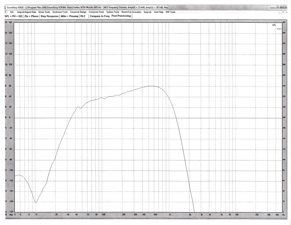
With that 1Khz filter you can see the upper response start to fall at 600Hz.
This was an interim measurement I took of the FF, NF and Port with the calculated BS included.
At 300Hz it's only a couple DB off the level at 600Hz and you can actually see that dip a little in the final measurements.
I hope that makes sense.
When I started this project it was always part of the plan to have the option to use the MiniDSP 2x4HD because the owner had amps to use and comparing the cost of the DSP to a passive crossover made it an attractive option. I did try to design a passive crossover and couldn't get good results on the bottom end which I attributed to the combination of the large rising response and the 2nd impedance peak on the low end. I would always end up with a peak between 40 and 100Hz.
Maybe someone who has done a passive crossover will chime in on their experience.
Very interesting to hear about how you approached implementing and verifying your BSC in the DSP Ron. I'm going to come back and reread what you wrote a few times to make sure I digest it fully. I have been working on prototyping a few speakers using both Minidsp and the hypex FA plate amps, and have been a bit unsure how to deal with BSC myself. The hypex recommendation is for a workflow along the lines of:
Measure and account for offsets/delays between drivers
EQ drivers to be flat 1-2 octaves below their intended crossover point
Apply crossover filters to all drivers
Apply BSC as a global EQ to the whole system, ahead of the individual driver EQ/crossovers
Of course, with measurements at every stage to verify results were as expected.
I found #4 to be counterintuitive, I would have thought it made more sense to apply BSC only to the woofer(s) in a 2 or 3way, but I believe the rationale was that doing it globally maintained better phase tracking between drivers or something along those lines. I have also heard some criticism of #2-3, but don't recall the arguments well enough to do them justice.
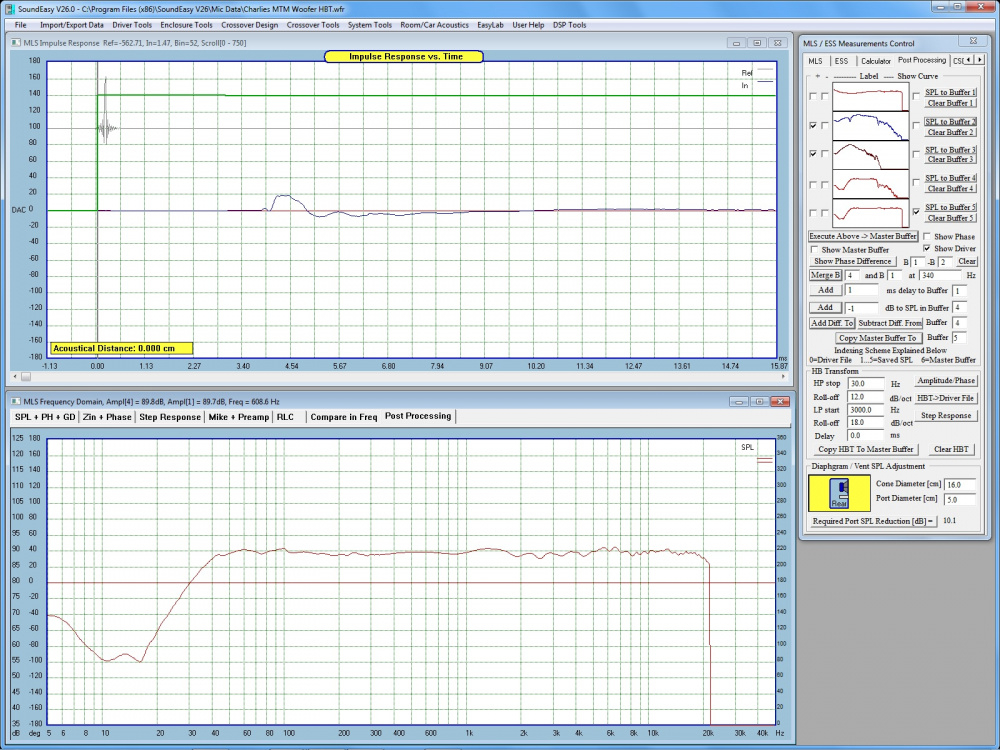
I don't know if this helps but I've blown up the buffer window from the final measurements in SoundEasy. You use the buffers to store measurements that you manipulate to build the final response.
Buffer 1 is the 1 meter far field response and with the window used is good down to 250Hz.
Buffer 2 is the nearfield woofer response with no gating.
Buffer 3 is the nearfield port response with no gating.
Buffer 4 is the created by adjusting the port response level to match the NF woofer level and adding them. You then apply the calculated BSC to the buffer.
Buffer 5 is used to splice buffer 1 and buffer 4 together. I believe I did the splice at 350Hz.
Comments
The rising response is what I measured on the tweeter axis with SoundEasy which lets you merge NF + Port with calculated BS applied and FF. The calculated baffle step was a little more than the typical 6db and the MCM datasheet shows a falling low end response but I don't know how they measured.
It was a bit of a puzzle on how to set up the DSP. Normally when you measure a passive system you end up with a rising response and you design a filter to pull the response down until it's flat. After you build the filter you measure again to confirm your design and leave out the step where you add the calculated BS because that's part of the filter now. With the DSP I ended up boosting the bottom end to bring it up so the response was flat and when making measurements to confirm the response using the calculated BS in those measurements. I did the DSP measurements with the 1Khz filter engaged.
With that 1Khz filter you can see the upper response start to fall at 600Hz.
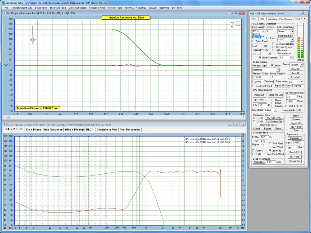
This was an interim measurement I took of the FF, NF and Port with the calculated BS included.
At 300Hz it's only a couple DB off the level at 600Hz and you can actually see that dip a little in the final measurements.
I hope that makes sense.
When I started this project it was always part of the plan to have the option to use the MiniDSP 2x4HD because the owner had amps to use and comparing the cost of the DSP to a passive crossover made it an attractive option. I did try to design a passive crossover and couldn't get good results on the bottom end which I attributed to the combination of the large rising response and the 2nd impedance peak on the low end. I would always end up with a peak between 40 and 100Hz.
Maybe someone who has done a passive crossover will chime in on their experience.
Ron
Very interesting to hear about how you approached implementing and verifying your BSC in the DSP Ron. I'm going to come back and reread what you wrote a few times to make sure I digest it fully. I have been working on prototyping a few speakers using both Minidsp and the hypex FA plate amps, and have been a bit unsure how to deal with BSC myself. The hypex recommendation is for a workflow along the lines of:
Of course, with measurements at every stage to verify results were as expected.
I found #4 to be counterintuitive, I would have thought it made more sense to apply BSC only to the woofer(s) in a 2 or 3way, but I believe the rationale was that doing it globally maintained better phase tracking between drivers or something along those lines. I have also heard some criticism of #2-3, but don't recall the arguments well enough to do them justice.
I don't know if this helps but I've blown up the buffer window from the final measurements in SoundEasy. You use the buffers to store measurements that you manipulate to build the final response.
Buffer 1 is the 1 meter far field response and with the window used is good down to 250Hz.
Buffer 2 is the nearfield woofer response with no gating.
Buffer 3 is the nearfield port response with no gating.
Buffer 4 is the created by adjusting the port response level to match the NF woofer level and adding them. You then apply the calculated BSC to the buffer.
Buffer 5 is used to splice buffer 1 and buffer 4 together. I believe I did the splice at 350Hz.
Ron