Site Links
Howdy, Stranger!
It looks like you're new here. If you want to get involved, click one of these buttons!
Quick Links
Categories
Who's Online (0)
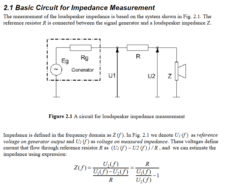
Some musings on T/S parameter measurements

Based on some recent discussions of driver impedance measurement methods and T/S parameters over at DIYAudio, I want to share some thoughts on T/S parameters and answer that age old question of "why are my measurements different from the manufacturers?"
Related discussion somewhat recently on this forum:
https://diy.midwestaudio.club/discussion/1830/box-sizing-for-sb15crc30-4-woofers
T/S parameters are defined as parameters for the driver "at rest". In other words, they are low voltage by definition. However, there is not a well defined specification for the conditions under which T/S parameters are measured, and there is not agreement from different manufacturers on the process either, so the inclination from a manufacturer may be to use whatever method provides the most marketable result.
Factors that influence the parameter results include voltage level for test, constant voltage test vs voltage divider test, ambient temperature and humidity, driver break in, probably more.
Voltage Divider Method
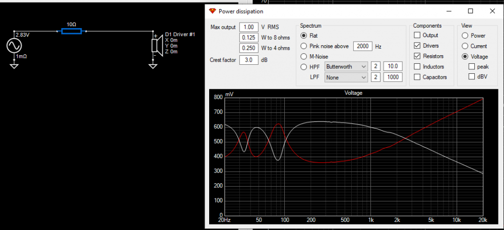
The common DIY method for testing a driver is to use a "voltage divider" method, because it is very simply done by placing a resistor in series with the driver and then measuring the voltage across the resistor. This "sense resistor" is typically in the range of 10-100 ohms.
The "problem" with this method is that the voltage that is present at the driver is not constant, the voltage present at the driver is proportional to the impedance of the driver. Easily observed in VituixCAD, the voltage across the sense resistor is a mirror image of the voltage present at the driver, neither are the original constant voltage sourse from the amplifier.
Constant voltage Method
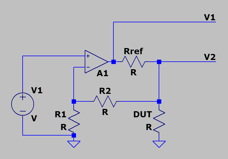
A solution to the voltage divider problem is to design an amplifier specifically for this task. What is required is that the sense resistor is placed inside the feedback loop of the amplifier, which will compensate for the voltage dependency of the voltage divider. In this operation, the gain of the amp now varies with the impedance of the driver in order to provide a constant voltage over frequency.
While this does "solve the problem", the question remains, was it even a problem to begin with. If we think about what is occurring in this constant voltage method, essentially the drive voltage is being increased when the impedance of the driver is increased, so especially at Fs the voltage is greater compared to the voltage divider method. So what if we just increased the drive voltage overall and keep with the simple voltage divider method?
Elevated drive voltage
To illustrate the effect of a difference in drive voltage on a driver, it is easily done in LIMP. Use PN noise and turn off averaging for a somewhat real-time measurement, then simply adjust the gain on your amp. The difference will be more easily observed in crappy drivers, but you should see Fs decreasing as you increase the voltage applied. So with this in mind, what is the "correct" Fs, and does any of this even matter?
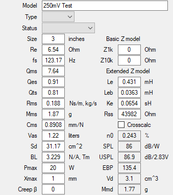
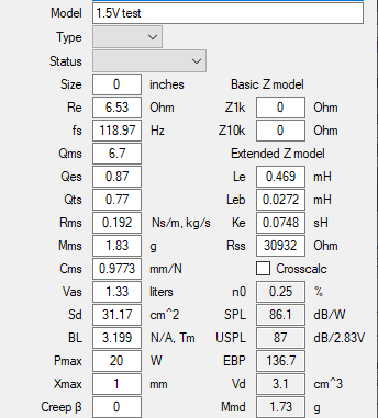
To answer this, I simply used a cheap 3" TB fullrange driver, no copper in the motor I am sure, and completed full T/S measurement at a voltage of 250mVrms, and again at 1.5Vrms.
At elevated voltage, Fs is indeed decreased by nearly 5Hz, but also Qts is lower, Cms higher, Vas higher, BL slightly lower.
250mV test:
1.5V test:
Comparing the cabinet model shows basically no difference at all:
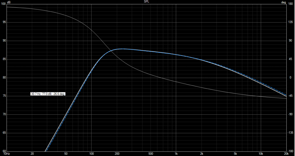
So what was the point of all this? The knowledge to be gained is that there are many factors that affect T/S parameters, and direct comparison of one's own measurements to the manufacturer data is futile, especially if focusing on single parameters like Fs for example. What does matter, is that the cabinet model is accurate, so any comparison of whether a T/S measurement is good or "matches" should be made using a cabinet model, since something simple as the test voltage can change the T/S parameter results, but the cabinet model can remain unaffected.


