Site Links
Howdy, Stranger!
It looks like you're new here. If you want to get involved, click one of these buttons!
Quick Links
Categories
In this Discussion
Who's Online (0)
zobel questions

I have an attachment showing three impedance graphs for an E150HE-44
No Zobel
Textbook Zobel, per driver stated parameters Re 6.6 ohms and Le 1.6 mH
modified units
I’m anticipating setting a 2nd order LP between ~400-600Hz (measurement dependent once drivers mounted in box). Running VituixCAD I see that while the Textbook units (the second chart) keeps the impedance at or below 8 Ohms going out to 20k, in the anticipated Xover region the impedance is not stable, actually dipping in this crossover region. C 23.5uF and R 8.25 ohms.
The result of modifying the units to C 22uF and R 22 ohms is shown in the third graph. While the impedance rises towards higher frequencies, the impedance is flatter and stable around the crossover frequency area (and out 3 to 4x this frequency band).
While the textbook units result would be the choice if crossing over to a tweeter, would it not be better in this case to have a more stable impedance in the crossover band where the filter is going to be working?
And, to what extent does the quality of the Cap in a Zobel matter ?
thx
Comments
People still use zobels?.
Apparently you’re not a fan. Why?
Thx
People still use textbook calculators?
And, the quality of capacitors in the filter circuit matters.
I used ‘textbook’ as referring to the standard calculation result; online or print.
And yes , I’m keeping my Dickason, D’Appolito, Bullock III (past Miami Ohio Prof- was an interesting guy), Weems…
The calculator is using a simplified single Le inductance value. Speaker motor inductance is more complex than a simple inductor, so you should not be surprised that better results are achieved by utilizing the real driver impedance. But, flattening the driver inductance before you design the crossover is pointless, unless you plan to use a textbook calculator for the crossover too") .
.
One particular design of mine had a problem with crossover between the mid woofers and tweeter - and nothing I did seemed to flatten things out the way that I needed. I dropped a zobel on the mid woofers, and suddenly the crossover did what I needed. Only time I've used one.
As referenced above, I had started by modeling in VirtuixCad (with the driver files for the E150HE-44) looking for designs for an initial filter, and was experimenting with / evaluating the employment (or not) of a Zobel filter, which led to the questioning of the dip in inductance, and hence this post. Then go, of course to measurement / adjustments / measurement... weighing primarily frequency, objective and subjective, considerations.
I was one of those kids that always asked why, and continue to this day.
I question not to question per se, but to get an understanding of the whys as I like a challenge of looking at a problem, and wondering if there are better solutions than the ‘standard textbook’ including ~VirtuixCad and related software based theses. I certainly enjoy this hobby and this audio club as its filled with experience and experimenters, those that have tried something different, and learned from those attempts that are shared. I, as I am certain others here, have a basement full of ‘rooftop toss worthy’ speakers, but have enjoyed the attempts. I like to try something a bit different (for me anyway) in each of my projects. And I certainly enjoy, and appreciate, everyone’s input.
Questions led me to an opportunity to meet up with Bob Bullock (Bullock on Boxes, paper version) at his office at Miami of Ohio in Oxford while I was living in Cincinnati. I had recently gone to a Rolling Stones Concert (8/94). Not having the ideal seats (actually any seat at a Stones concert rocks) led me to an idea about how to better the sound image at a concert, and in its final extension for a playback set-up. Coming up with a unique solution to the problem I saw led me to my first of a couple issued speaker patents (publication date 9/96).
And I continue to question, and sometimes irritate (sorry), to this day.
Thanks again for everyone’s input, suggestions, and all comments. BTW, did you know that scents and fragrances can be communicated /shared through the internet? I just recently picked up the scent of Ode de l’grade 40. A bit heavy and gritty for me, I prefer grades 120 and up – but to each their own. All the best.
It's called VituixCAD, there is no R.
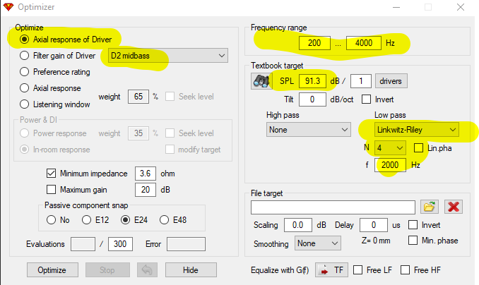
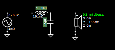
For a basic starting point, slap a couple parts in the crossover, set the low pass target in the optimizer and optimize the driver response. Limit the frequency range for optimization with some practical limits to cover the knee of the response.
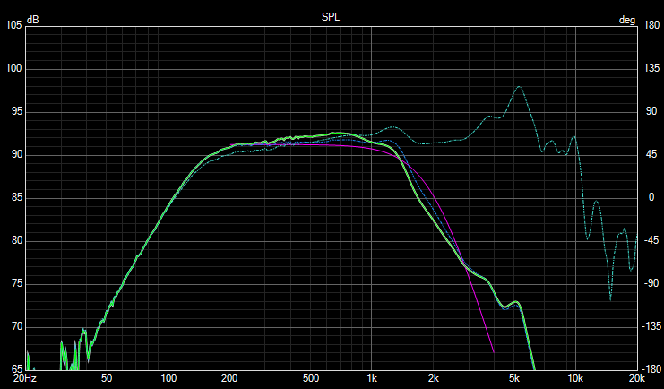
Here's an example. Dashed line is the raw response measured in the intended cabinet.
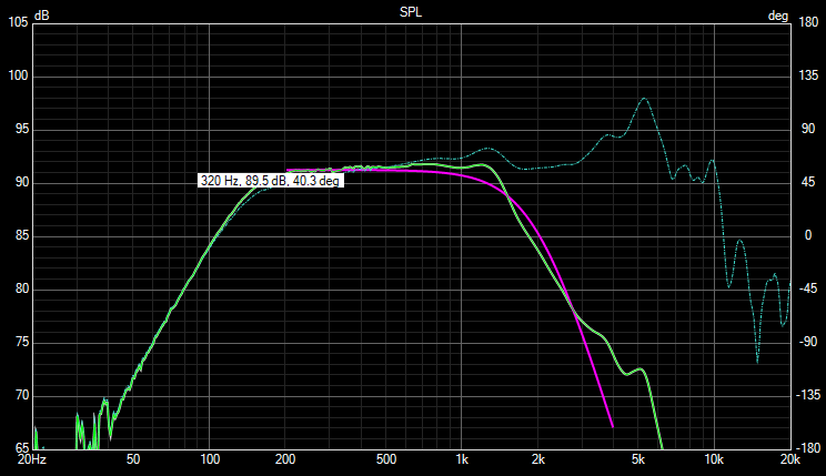
Similarly, if I do the same thing, but use a zobel first, the result is some different part values, but not that much difference in response. In fact, I was able to get closer to the target response with the basic 2 component filter without zobel in this case.
The way that I see it, and have utilized zobels in the past is really not for the sole purpose of flattening the impedance, but as Rjj above alluded to, I have used them to shape the response when it wasn't easily or satisfactorily achieved with the standard filter arrangement. And yes they always need adjustment, as a matter of fact I don't even use the textbook calculator while in the sim software, I just make a guess and go from there.
good to know - thx guys
The zobel will provide a flat impedance to the filter components before it, so your textbook filter will provide a textbook transfer function. But there is still the problem that the frequency response is not textbook flat, and inherent acoustic delays due to driver locations generally prevents a textbook filter transfer function from being the correct solution in a complete system. So just put parts where they need to be to get the response of the complete system worked out. Maybe a damped capacitor (aka zobel) in parallel with the driver is the right solution, but not where I would be starting in filter design.
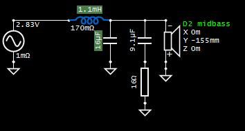
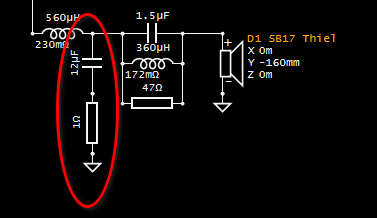
FWIW A lot of times I end up putting a small resistor in series with the woofer capacitor, it provides some ability to soften the knee of the filter response, and only a small change to the filter slope provided you keep this value small. Like this (it's not a zobel):
I do like PCDs LR2-4 text book calculator to get started. When I need a notch, I'll use textbook values with the impedance at the notch midpoint to get started. I like to watch the filter response along with the frequency response.
Is it fundamentally different than a 1st order filter with zobel? Either way, the resistor's purpose is to control how much high frequency is shunted to ground.
(just stirring the pot)
Yes it is, and no it isn’t")
Thx for all the input !
I'll be doing a bunch of sims, and looking at the affect of placing a small resistor as highlighted- thx.
Once box is completed, drivers placed I plan to first get the port length set (all per measurement- focusing on frequency of combined W and port, as while impedance shows net box tuning I'll be targeting the combo frequency of the pair)
And, while the sims will put me in the ballpark (per the actual driver files), why not just then take a look at using my miniDSP (biamped set-up) to play with the LP and HP filters- easy to select and change and actual frequency based net output results. Then I'll go back to the sims and look to duplicate the filters - at least using the orders and Xover points. At that point I can go in and work with the alternatives for adjustments. I'm liking the idea of the small resistor btwn cap and ground as an adjustment to the knee, and then look for needs for a notch...
Again, appreciate the ideas- I'll post as I get some results
Measurement and design process with VituixCAD can be the same process whether passive, active, or DSP. For the miniDSP you just set it in the options then use active blocks as needed. The block parameters can be directly transferred to the DSP or the biquads copied and pasted for more advanced stuff.
If you take the basic miniDSP 2x4, the complete DSP structure can be reproduced in VituixCAD like this.The PEQ blocks can of course be anything the miniDSP supports.
This may be above my current 'old dog' pay grade, but definitely worth me doing some homework.
I wasn't thinking of being able to bring in a series of parametric EQs as well- fantastic !
follow-up: Actually, using the active blocks w/in VituixCAD (and getting into minDSP, even if manual) not a pb.
next up: looking into pulling files from REW into VituixCAD - which would be great for the AN driver's in box measured freq response
follow up- now to get the download in the right format... 2 column space delim, output came as 3 col coma delim
Huh?
https://kimmosaunisto.net/Software/VituixCAD/VituixCAD_Measurement_REW.pdf