@kenrhodes said:
That's not 25 ohm to ground. L pads are cool things.
I'm still not convinced but willing to learn, Ken.
I've had several tweeters that refused to play flat with just a resistor inline or a resistor to ground. They needed that L pad, and some were ok before the first cap, and some wanted it after the (3rd order) caps.
But Chahly - Stahkist don't want speakers that look good, Stahkist wants speakers that sound good!
My understanding is that an Lpad should be applied after the XO to maintain Z seen by the amp.
A series R in front of the XO is to reduce the level of signal seen by the XO and subsequently by the Tweeter.
I just don't understand the physics of the equivalent of a 25 Watt light bulb to ground without a filter in series with the amp output being acceptable practice. Please entertain me/us for my/our edification when you guys have time/energy to do so.
Maybe Wolf can chime-in here or even dcibel to give us a more in depth description of what is actually going-on electrically?
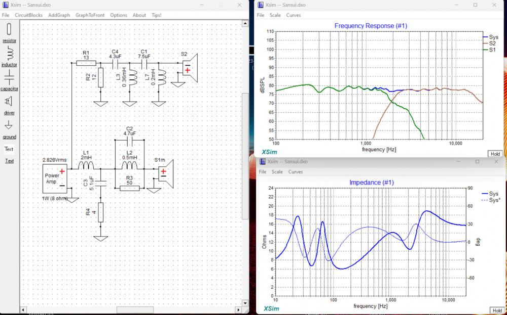
The impedance plot is what the amplifier sees. The load is dominated by the woofer.
An L-pad is a basic voltage divider circuit (used in almost every electronic device). In this case providing attenuation for the tweeter. Unless it is poorly implemented it should have little effect on the load that the amplifier sees (many times beneficial).
It does feel kind of like bad practice to put a parallel resistor before the highpass, but if it works for what you need it to do and doesn't cause an issue
I crossed a back-to-back pair of those tweeters at 1.6kHz LR4 to a 15" in a nude dipole system in 2018ish that I demoed at the Meniscus DIY event that year. Now THAT was low.
When you use a pair of them in that way it has a very different response, more like a horn with increased output above 1.5kHz, so that made it possible.
I used that tweeter in an MTM with a pair of TCP115-4 in series. I crossed it right at 2K like you are. The pair of woofers were struggling way before the tweeter. I think you'll be fine.
@PWRRYD said:
I used that tweeter in an MTM with a pair of TCP115-4 in series. I crossed it right at 2K like you are. The pair of woofers were struggling way before the tweeter. I think you'll be fine.
I think we tend to ignore woofer mechanical capabilities when determining where to cross our tweets. I wouldn't cross this tweeter at 2K to a 6.5" with, say, 6mm Xmax that I also expect to play loud. Any given 4-5" woofer short of the Dayton Epique I would not hesitate to cross at 1.8 or possibly a bit lower.
Expect 13 ohm series resistor to dissipate the most power in the OP schematic.
In Xsim, you have these features:
Xsim simulates with sine wave only, useful for proportions of power, but not good depiction of actual power dissipation for real audio, a bit much for determining power rating for resistors.
In VituixCAD, same option exists with a few noise selection for a more realistic picture of real audio:
Default setting of "pink noise above 2000Hz with 13dB crest factor" is pretty good for normal audio power dissipation worst case for sizing parts.
L-pads before or after is often determined by necessity. There are audio systems that control the full speaker volume with an L-pad. Putting the filter before the L-pad will help control the amount of power that gets turned into heat, the inverse is also true. An L-pad can be used to help voltage sensitive components.
In this application I doubt you would overload a 10w resistor.
The resistors are placed directly across the amplifier if they are at the input in a conventional Lpad arrangement. Not only does it warm up the resistors considerably, it also loads the woofer section in a parallel xover and parallels them across the woofer load. This can make for a really low impedance and should be avoided. The series resistor before or after the network is fine, the shunt should only come after.
@Wolf said:
The resistors are placed directly across the amplifier if they are at the input in a conventional Lpad arrangement. Not only does it warm up the resistors considerably, it also loads the woofer section in a parallel xover and parallels them across the woofer load. This can make for a really low impedance and should be avoided. The series resistor before or after the network is fine, the shunt should only come after.
Thanks Ben - you are the crossover mastah
Makes perfect sense.
But Chahly - Stahkist don't want speakers that look good, Stahkist wants speakers that sound good!
@Wolf said:
The series resistor before or after the network is fine, the shunt should only come after.
Part value is very important here, in both cases. Use the tools available in the software for evaluation in any case, generally I would try to avoid resistors at amp side of the filter unless absolutely necessary, there is usually a way to get the response you are after without doing this at all.
@PWRRYD said:
I used that tweeter in an MTM with a pair of TCP115-4 in series. I crossed it right at 2K like you are. The pair of woofers were struggling way before the tweeter. I think you'll be fine.
Do you have a crossover diagram for those?
I am learning and would like to see how you did yours.
I don't disagree with what Wolf and Dcibel have said other than the idea that these are rules. I have seen speaker manufactures intentionally use bigger resistors to drop the voltage going to smaller capacitors and inductors. Resistance is futile, wait that's not it... resistance is cheap.
This article explains some of the advantages of moving the shunt when necessary, sometimes even changing the "L" orientation according to load.
@dcibel- I don't see the issue some people have with placing the series resistor at the input. The advantages are that it does not tilt the FR, and that it helps keep the impedance phase more linear. Being that the post filter still highpasses the bandwidth, the resistors do not get hot, nor is it a direct load prone to such a result.
Ken, I wasn't trying to imply it was a hard and fast rule, just that it can be a poor decision to do it that way especially to the uninformed. I still do not think it is a good idea mainly due to the impedance and AC-shunt issues.
The different positions as in flipped L, T-pad, prior series and after shunt, etc are all methods that add electrical damping where required.
@Wolf said: @dcibel- I don't see the issue some people have with placing the series resistor at the input. The advantages are that it does not tilt the FR, and that it helps keep the impedance phase more linear. Being that the post filter still highpasses the bandwidth, the resistors do not get hot, nor is it a direct load prone to such a result.
Here's the power dissipation for the circuit above. Both series and shunt resistors are similar values at 13 and 12 ohm respectively. Series resistor is the worst offender for power dissipation, not the shunt, although both are "bad". That is all.
Removing the shunt resistor, the 13 ohm series resistor alone is much happier, fine in most cases for a tweeter circuit and a shunt alone would be much worse (similar to above), but I would still tend to avoid just as a "best practice", there is always another way to achieve the FR goal.
Jakes_dad, I hope we haven't highjacked your thread too much. I think it has been a great discussion and goes to show you how circuit optimization can be a very tedious task.
Wolf and Dcibel, thank you for chiming in on this. I love seeing your viewpoints and explanations.

Comments
How loud you going to play it? That matters.
I'm just curious if that 25 Ohms to ground at the front of the tweeter XO is just wasting power?
It isn't filtered at all . . .
That's not 25 ohm to ground. L pads are cool things.
That's a good question. It's not gonna be a party speaker, mostly used for background music.
Try it and see - if it gets raspy then its too loud or XO'd too low, right?
I have run CD's down way lower than recommended because I don't play them at ear splitting SPL and they sound great.
I'm still not convinced but willing to learn, Ken.")
I've had several tweeters that refused to play flat with just a resistor inline or a resistor to ground. They needed that L pad, and some were ok before the first cap, and some wanted it after the (3rd order) caps.
My understanding is that an Lpad should be applied after the XO to maintain Z seen by the amp.
A series R in front of the XO is to reduce the level of signal seen by the XO and subsequently by the Tweeter.
I just don't understand the physics of the equivalent of a 25 Watt light bulb to ground without a filter in series with the amp output being acceptable practice. Please entertain me/us for my/our edification when you guys have time/energy to do so.
Maybe Wolf can chime-in here or even dcibel to give us a more in depth description of what is actually going-on electrically?
Thanks!
Sorry for the apparent thread high-jack . . .
You can see the effect of the series or parallel or both resistor in Xsim (or Vituixcad) on tweeter response.
What does the amp see, RJJ?
The impedance plot is what the amplifier sees. The load is dominated by the woofer.
An L-pad is a basic voltage divider circuit (used in almost every electronic device). In this case providing attenuation for the tweeter. Unless it is poorly implemented it should have little effect on the load that the amplifier sees (many times beneficial).
It does feel kind of like bad practice to put a parallel resistor before the highpass, but if it works for what you need it to do and doesn't cause an issue")
I crossed a back-to-back pair of those tweeters at 1.6kHz LR4 to a 15" in a nude dipole system in 2018ish that I demoed at the Meniscus DIY event that year. Now THAT was low.
When you use a pair of them in that way it has a very different response, more like a horn with increased output above 1.5kHz, so that made it possible.
I used that tweeter in an MTM with a pair of TCP115-4 in series. I crossed it right at 2K like you are. The pair of woofers were struggling way before the tweeter. I think you'll be fine.
I think we tend to ignore woofer mechanical capabilities when determining where to cross our tweets. I wouldn't cross this tweeter at 2K to a 6.5" with, say, 6mm Xmax that I also expect to play loud. Any given 4-5" woofer short of the Dayton Epique I would not hesitate to cross at 1.8 or possibly a bit lower.
Jakes_dad what woofer are you using?
Dayton DC160-8, around 3mm Xmax.
Expect 13 ohm series resistor to dissipate the most power in the OP schematic.
In Xsim, you have these features:
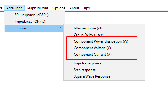
Xsim simulates with sine wave only, useful for proportions of power, but not good depiction of actual power dissipation for real audio, a bit much for determining power rating for resistors.
In VituixCAD, same option exists with a few noise selection for a more realistic picture of real audio:
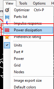
Default setting of "pink noise above 2000Hz with 13dB crest factor" is pretty good for normal audio power dissipation worst case for sizing parts.
Have fun, try not to let out the magic smoke")
Yeah, big no-no. Either move the whole after the xover, or just the parallel resistor.
InDIYana Event Website
L-pads before or after is often determined by necessity. There are audio systems that control the full speaker volume with an L-pad. Putting the filter before the L-pad will help control the amount of power that gets turned into heat, the inverse is also true. An L-pad can be used to help voltage sensitive components.
In this application I doubt you would overload a 10w resistor.
The resistors are placed directly across the amplifier if they are at the input in a conventional Lpad arrangement. Not only does it warm up the resistors considerably, it also loads the woofer section in a parallel xover and parallels them across the woofer load. This can make for a really low impedance and should be avoided. The series resistor before or after the network is fine, the shunt should only come after.
InDIYana Event Website
Thanks Ben - you are the crossover mastah
Makes perfect sense.
Part value is very important here, in both cases. Use the tools available in the software for evaluation in any case, generally I would try to avoid resistors at amp side of the filter unless absolutely necessary, there is usually a way to get the response you are after without doing this at all.
Thanks, I will add that to my file of things not to do.
Do you have a crossover diagram for those?
I am learning and would like to see how you did yours.
I probably do. It'd be on my work laptop. I'll look for it tomorrow and post it up.
I don't disagree with what Wolf and Dcibel have said other than the idea that these are rules. I have seen speaker manufactures intentionally use bigger resistors to drop the voltage going to smaller capacitors and inductors. Resistance is futile, wait that's not it... resistance is cheap.
This article explains some of the advantages of moving the shunt when necessary, sometimes even changing the "L" orientation according to load.
https://www.electronics-tutorials.ws/attenuators/l-pad-attenuator.html#:~:text=Basic L-pad Attenuator Circuit&text=The two resistors are connected,“L-pad Attenuators”.
Once again NOT disagreeing just wanted to point out some alternative uses and reasons to break from what is normally best practices.
@dcibel- I don't see the issue some people have with placing the series resistor at the input. The advantages are that it does not tilt the FR, and that it helps keep the impedance phase more linear. Being that the post filter still highpasses the bandwidth, the resistors do not get hot, nor is it a direct load prone to such a result.
Ken, I wasn't trying to imply it was a hard and fast rule, just that it can be a poor decision to do it that way especially to the uninformed. I still do not think it is a good idea mainly due to the impedance and AC-shunt issues.
The different positions as in flipped L, T-pad, prior series and after shunt, etc are all methods that add electrical damping where required.
InDIYana Event Website
Here's the power dissipation for the circuit above. Both series and shunt resistors are similar values at 13 and 12 ohm respectively. Series resistor is the worst offender for power dissipation, not the shunt, although both are "bad". That is all.
Removing the shunt resistor, the 13 ohm series resistor alone is much happier, fine in most cases for a tweeter circuit and a shunt alone would be much worse (similar to above), but I would still tend to avoid just as a "best practice", there is always another way to achieve the FR goal.
Jakes_dad, I hope we haven't highjacked your thread too much. I think it has been a great discussion and goes to show you how circuit optimization can be a very tedious task.
Wolf and Dcibel, thank you for chiming in on this. I love seeing your viewpoints and explanations.