Ok, just looked at the close mic measurements and what is weird is, the woofer rolls off after 60 hz. When I originally took measurements it was rolling off around 200 hz. looking at the impedance curve shows the minimum is at 60 hz 3 ohms. I must have messed up my crossover or something on that one. The other speaker measured 3 ohms at 3khz. everything down low was higher than that. will have to look it over.
Are they just replacement cones or complete passive radiators and could they be glued to a cutout effectively if just a cone?
Looks like those are replacement diaphrams.
Passive radiators must have spiders and surrounds to create "springiness".
Some folks have experimented with using actual woofers for PRs, or knocking off the magnet and
using the rest of the woofer as a PR - but then it's hard to change the weight.
But Chahly - Stahkist don't want speakers that look good, Stahkist wants speakers that sound good!
Are they just replacement cones or complete passive radiators and could they be glued to a cutout effectively if just a cone?
Looks like those are replacement diaphrams.
Passive radiators must have spiders and surrounds to create "springiness".
Some folks have experimented with using actual woofers for PRs, or knocking off the magnet and
using the rest of the woofer as a PR - but then it's hard to change the weight.
Nah, they just need mass and surrounds. Spiders are a bonus as they add linearity.
That's FR, if he has the IMP sweep and/or crossover to show utilizing an IMP comp to correct that issue, it'd be even more helpful.
That alone is a great eyeopener.
@ugly_woofer said:
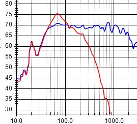
For those that have never played with low crossover points, this is what can happen. This is a Satori woofer with and without lcr impedance comp.
Great example of what I was talking about Nick. The bump isn't due to the box, port/PR tuning, internal standing wave, etc. it's the interaction of the LP filter and the driver's impedance. Thanks for the visual refresentation.
Edit: Oh wait... you brought this phenomenon up first, I just chimed in after that.
Just so everyone understands... how big were the values of components in your LCR comp circuit to fix the hump? I'm guessing fairly large considering the low frequency range.
@PWRRYD said:
Just so everyone understands... how big were the values of components in your LCR comp circuit to fix the hump? I'm guessing fairly large considering the low frequency range.
Haha, I just tried to sim something reasonable in VituixCAD and couldn't so was coming to ask that exact question!
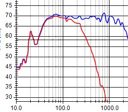
I've run into a couple of woofers that needed impedance compensation in order to get the low end FR to flatten out. The most recent were the Subterfuges that I brought to Ankeny last year. Here are the FR and impedance graphs with and without compensation.
Comments
Ok, just looked at the close mic measurements and what is weird is, the woofer rolls off after 60 hz. When I originally took measurements it was rolling off around 200 hz. looking at the impedance curve shows the minimum is at 60 hz 3 ohms. I must have messed up my crossover or something on that one. The other speaker measured 3 ohms at 3khz. everything down low was higher than that. will have to look it over.
Looks like those are replacement diaphrams.
Passive radiators must have spiders and surrounds to create "springiness".
Some folks have experimented with using actual woofers for PRs, or knocking off the magnet and
using the rest of the woofer as a PR - but then it's hard to change the weight.
Nah, they just need mass and surrounds. Spiders are a bonus as they add linearity.
What JR said.
It's not hard to add weight to woofers converted to PR. I use stick on wheel balancing weights stuck to the inside of the voice coil.
For those that have never played with low crossover points, this is what can happen. This is a Satori woofer with and without lcr impedance comp.


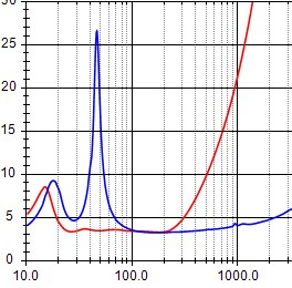
I’m assuming this just the raw impedance measurement (ie w/o a LP filter)?
Thx
That's FR, if he has the IMP sweep and/or crossover to show utilizing an IMP comp to correct that issue, it'd be even more helpful.
That alone is a great eyeopener.
What was I thinking? Ha
Great example of what I was talking about Nick. The bump isn't due to the box, port/PR tuning, internal standing wave, etc. it's the interaction of the LP filter and the driver's impedance. Thanks for the visual refresentation.
Edit: Oh wait... you brought this phenomenon up first, I just chimed in after that.
Just so everyone understands... how big were the values of components in your LCR comp circuit to fix the hump? I'm guessing fairly large considering the low frequency range.
Haha, I just tried to sim something reasonable in VituixCAD and couldn't so was coming to ask that exact question!
Here's the impedance raw and compensated. The lcr parts are 13mh, 800uf and 3.5 ohms.
I should have included this to begin with, for clarity.
I've run into a couple of woofers that needed impedance compensation in order to get the low end FR to flatten out. The most recent were the Subterfuges that I brought to Ankeny last year. Here are the FR and impedance graphs with and without compensation.
The LCR parts were 12mh, 1000uf and 3.6 ohms.
I am positive that is the problem. My response looks exactly like that. Will mess with it when I get some time. Thanks Nick!