Site Links
Howdy, Stranger!
It looks like you're new here. If you want to get involved, click one of these buttons!
Quick Links
Categories
In this Discussion
Who's Online (0)
Measurements and a WTƒ moment ...
Whats going on?

Playing around with the 'not a Khanspires' on a never ending quest to get better sound by tinkering with the minidsp 2x4. Accidentally put a very sharp shelf filter in around 3k, and with no music playing, the speakers produced a VeRy audible whine. Took the shelf out, whine gone. The whine shouldn't have happened.
Just how audible is the minidsp?
... so working on getting measurements accurate enough to start working on a passive crossover with winpcd, or ARTA, or both. This is going to be a learning experience!
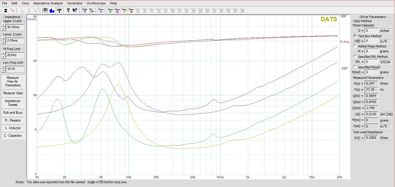
These are the DATS measurements. The green trace is with both rs225p's being driven in parallel, the purple trace is only one rs225 being driven. They share the same ported volume. The gold trace is with both rs150p's being driven parallel, the blue trace is only one being driven. They share the same sealed internal enclosure. The rs225's hump @8k, and the rs150's hump at 550, and 1.5k, are also in Dayton's specs.
Does this look normal? When measurements for a single woofer are entered into winpcd, tell it there are two woofers, enter the spacing, etc., the impedance plot looks just like the single woofer's plot.
Shouldn't winpcd add those purple traces together and get the green trace?

Comments
The x-o programs can’t take a single woofer in a large volume and convert it to two woofers in a smaller volume.
You must use and model the two woofers as one or use response modeler to create a single woofer impedance graph in half the volume with the same tuning.
Unless you are doing a center channel there’s not much benefit from separating the woofers.
This!
Will have to remove binding posts, cut and resolder wires later to try Ed's 'hold the woof' method, and I had already started to model it the way John mentioned, so ...
Measurements were taken with both woofers driven @1 meter, so I should not have to add in any bsc ...right? The .zmas' used would be the green and gold traces from first post.
And this is what I came up with modeling it as John mentioned.
To my untrained eyes; phase could line up better, the transfer? functions aren't the prettiest, that ohm load is going to be a bit demanding, and there is a peak/valley @~3k who's remedy eludes me.
Now give me your honest opinion. How does it look? What's wrong? What's right? What needs tweaked? How am I doing? Am I totally on the wrong track?
Please comment, good or bad.
As you know for a 2.5 a you would need nearfield, blend and minimum phase to get the lower x-o right.
Would this be a valid alternative to the SW manipulation?
For a tower speaker with the woofer near the floor, for the far field measurement, I think a longer measuring distance with a short gate has the advantage of capturing the spl increase from the lower woofer while avoiding the floor reflections. I'm sure that is debatable, but my thought is that if the gate is good down to say 400 Hz that should be on the back side of the baffle effect, enough to be able to set the near field SPL in the blender.
For the near field only one woofer is required, it doesn't matter which one as you are missing the baffle and any other gain from the proximity to the floor.
Removed the resister across the woofer, flattened the tweeter just a little, the reverse null looks better @woofer/mid, and the ohm load is a bit more friendly in the bass.
New one on left. May have removed too much bass. I like bass.
New one on top. The transfers look worse. Impedance looks better, still drops to ~4 ohm on top, don't figure that should be a problem since there's not going to be much power needed up there.
Uh oh ... might have screwed up ... resistance was left, at what I assume, is the default setting of .35ohm. How bad is that going to be?