Please review the site Rules, Terms of Service, and Privacy Policy at your convenience. Rules, TOS, Privacy
Get familiar with the reaction system: Introducing the Reaction System

notch filter help/suggestions- thx

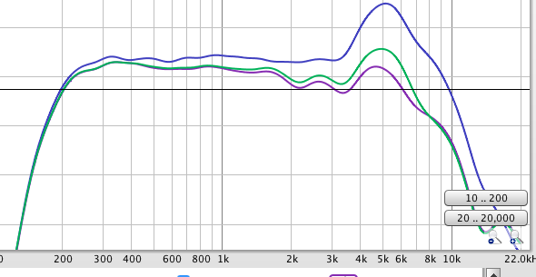
I've been working on developing a notch filter to reduce the mid's rise at 5,000 Hz, from chart the blue is pre-notch, the green is w notch R 12.5 ohm, cap 32uF, and L .03, and the purple notch is R 12.5ohm, cap 10.uF2, and L .08- but I cannot seem to get it down and narrow it out further (I've been adjusting values but can't seem to pull out this rise any further- ideas?  While the purple level is close its too wide- any suggestions- thanks 

its an 8ohm mid (actually a coax but this is just a chart of the mid), 

Comments

  • You are on the right track - the ratio of cap <-> coil controls the frequency, and the resistor controls the Q - whether narrow or broad. You might look at a Zobel - I've found that when a crossover just won't behave on the "top end" of a woofer, usually a Zobel will help out.
    tajanes
    But Chahly - Stahkist don't want speakers that look good, Stahkist wants speakers that sound good!
  • Let's start from the beginning...

    Which type of notch are you using? Parallel (with each other placed in series with driver)? or Series (with each other placed across the driver)?

    Where is the tentative xover point to be? Active or passive?

    If this is a parallel notch, it's not unheard of to have a 40 or 50 ohm resistor there. In your simulation, set it really high to 1000 or something in that range. Then adjust the L/C to get it centered on the peak, and the dip in the sim will be where you want it. Then just reduce the resistor value until it's dialed in. This is mainly if it just needs to be flattened out as far as this process goes.

    If this is above the xover point, and it is a nasty breakup, then you really should suppress it to -40dB from reference with the xover applied. That will minimize it's audibility. -25dB minimum, -40dB desired, and -50dB makes it no longer a concern at all.

    If this is a series notch, and you are running active xovers, the circuit will not have the upstream voltage divider necessary for it to work appropriately. I have however found in some cases where a brute-force LC shunt or 'bottomless trap' (with only coil's DCR for R value) is most effective at reducing higher Q peaks and/or breakups.

    tajanes
  • a) parallel, b) tentative xover depending on net rolloff of mid net the notch filter, and passive btwn mid and tweeter c) this is the program http://www.mh-audio.nl/parallelnotchfilter.asp , d) this notch filter will be just below the xover point (using the modified fall off to set the tweeter HP level and filter slope)

    I appreciate you help with this,
    Andy

  • fyi, bummped resistor to 46.5, cap at 20 and L .04, getting closer... 
    going in right direction- thanks
  • Can you post the FRD file somewhere?
     John H, btw forum has decided I don't get emails
  • I can attach a REW file to an email (but not here?) if you have REW send me an email at taj.janes@gmail.com and I'll attach and reply

    here is the last freq chart per 46.5 R, cap 20 and L .04

  • Is this breakup at 5K? I would try to cross below this if I could.
  • I've never messed with REW. Ed P could probably tell us if that's an FRD file that needs to be exported from REW.
     John H, btw forum has decided I don't get emails
  • I'm with Duane here, as I feel that 5.5k is likely way to high, even for a coaxial of the type you have there.

    I'm betting this is the same coaxial that Keith Etheredge used in his 'Keeping up with the Jones' winning entry build.

    He did a good job making it smooth out, though did hammer it into place. It might provide some ideas for what worked well.

  • thanks, I'll take a look
    what I'm concerned with and trying different component values to try to work around, is the notch filter is causing wave disruption / ripple- take a look at first posted pic, the blue is pre-notch, and the green and purple are with notch filters- thinking I have a miss-match of the cap and coil values causing ripple 2000 to 4000 ?
  • edited November 2018
    What kind of driver is this? That looks like the response of a silver flute driver, which I cave found to sound poor if pushed that high up anyway. I’d hammer it flat at a minimum, or even make it a dip, with a parallel notch, then still cross it steep before that point. At least with the sf drivers with a nearly identical breakup, whatever is going on with the cone breakup up there is ugly sounding imo.
  • tajanes said:
    thanks, I'll take a look
    what I'm concerned with and trying different component values to try to work around, is the notch filter is causing wave disruption / ripple- take a look at first posted pic, the blue is pre-notch, and the green and purple are with notch filters- thinking I have a miss-match of the cap and coil values causing ripple 2000 to 4000 ?
    Welcome to "Q". Since you want the notch to cover 3.5K to 8K, of course it will affect frequencies above and below that range. XSim should be able to model this pretty easily, you can use the sliders to change any of the values and see results in near real time.
    tajanes
    But Chahly - Stahkist don't want speakers that look good, Stahkist wants speakers that sound good!
  • edited November 2018
    I really appreciate all suggestions and info !

    driver is a celestion coax FTX0617

    tried a zobel, not much dif, but putting toys away for the night and starting up in am with new componet values I'm now seeing light at the end of the tunnel - still have work to do, but its getting there -this chart is w inclusion of tw 2nd L-R above notch level on mid (using notch to let mid roll off)
  • Just a caution to make sure you test in place.  With box resonance an rear wave addition the results may not match your sim.
    tajanes
     John H, btw forum has decided I don't get emails
  • edited November 2018
    this last graph (previous post) was measured at listening area, don't see box reasonance issue as its fairly open design and padded, below is chart from rear (top speaker only) at about 18 inches

  • That rear response looks pretty good imo.  What's the front response at 30 inches or so look like?  Also what's the vertical scale divisions?
     John H, btw forum has decided I don't get emails
  • Vertical scales were 10, so I've got some more work to do.  I have a few more parts ordered...
  • notch filter ended up with: 60ohm R, cap 8.2uf, and L 0.1, also put in an Lpad (from an old project) for the coax tw, and ran the mid with just the notch, put in a 3rd order for tw.  Measurements shown at 15deg approx 18in.  Coax dips around 2150 so eq'ed a bit w dsp.
    ThumperTom
  • and with the dipole Ws...
Sign In or Register to comment.