Site Links
Howdy, Stranger!
It looks like you're new here. If you want to get involved, click one of these buttons!
Quick Links
Categories
In this Discussion
Who's Online (0)
Difference in responses between programs

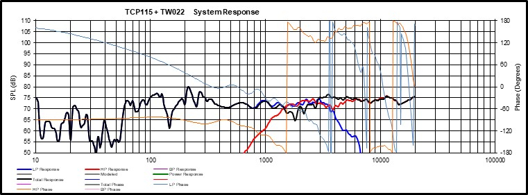
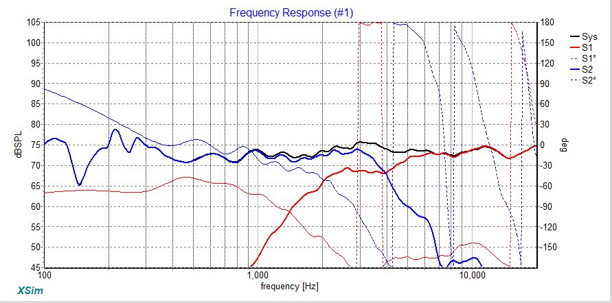
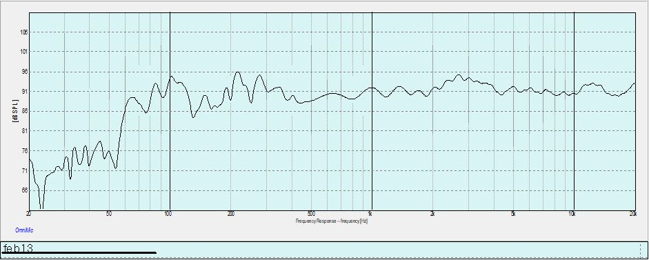
Just wondering if people get different results in response curves between different modeling programs? I have the latest version of PCD on one of my Windows 10 machines (doesn't work on the other one) and Xsim. Using the same frd and zma files I get two different results between the two programs - same crossover values, same z offset, etc. The only thing that isn't entered into Xsim is the vertical offset of the drivers which i'm not sure how to do. I get two pretty different results between the two programs. I measured the speaker in room and I get a response very close to the Xsim results. Kind of makes me wonder if PCD has some issues with the Windows 10 system or if it just something on my computers.
Comments
Well, you've already answered your own question - the offset value is not represented the same between Xsim and PCD.
Xsim offset is total offset, the difference in distance from mic to speaker. You can use Pythagorean theorem to figure it out...
a^2 + b^2 = c^2
a = distance mic to baffle (tweeter)
b = y offset between drivers
c = distance mic to woofer
a - c = offset
Looking at your measurement, Xsim appears to be closer to reality, so you can work back from the math above to determine the offsets needed in PCD to reproduce the same response.
Easier solution is to just switch to VituixCAD. In Vituix, keep tweeter x,y,z coordinates at 0,0,0, then enter the woofer offsets relative to the tweeter location, similar to PCD. It even has a tool built in for determining offset by the 3 measurement method for USB mics.
Also - How did you arrive at your PCD Z offset? Did you calculate it using the three measurement method?
Yes - as per Jeff B's white paper.
But shouldn't PCD be closer to correct as it has all the correct offsets in it?
Only if you've determined the offset value accurately.
Take the offsets you have in PCD, do the math to determine equivalent offset in Xsim and you should see closer agreement between the simulated response. If they don't agree at this point, you probably have some other value entered into PCD like a changed mic axis.
Alternatively, determine z offset by working back from the offset entered in Xsim and see how different they are from what you've determined.
Forgetting about math equations, you can just go through the whole delay 3 measurement delay determination in both Xsim and PCD to arrive at the necessary delay value for both applications.
Also keep in mind that Xsim a positive delay means driver further away from the mic, and in PCD a negative Z offset means further away from the mic.
To make things a bit easier, once you determine the offset in Xsim, you can enter this value as the offset in PCD directly (convert to meters and enter as negative value), but you must remove the Y offset so this value is entered as Z offset and is the only offset entered. This will provide agreement between the simulations, but you will loose any insight of how your crossover operates off-axis in PCD.
Does Vituix work with OmniMic files or do you need a different microphone?
Any FRD data is usable, but you won't get the added benefits of accurate insight into power response when using a single channel USB mic. Like anything else, the result is only as accurate as the input data. In other words, it'll do everything that PCD does but is much nicer software than that clunky old spreadsheet.
For offset determination go to Tools -> Auxiliary -> Time Align
If you are unsure of your Xsim offset, save out the summed response from PCD. In the Xsim frequency response window click on Curves then Get File and load the FRD from PCD as an overlay. Adjust the woofer offset until the curves match
One thing in PCD that I sometimes forget to set is the "Listening / Measuring Distance". I think it defaults to 2 meters and it needs to be set to match the microphone distance when measurements were made.
Ed, you beat me to it.
I always just leave that at 2 meters - only time I change it is when measuring for the z offset. Will try changing it and see what happens.