On the output jack ground - it depends on whether they are ground isolated jacks or not. If not, and they are on the same metal panel as the input jacks, ground will already be there, so only tie the shield of the output cable to the board ground.
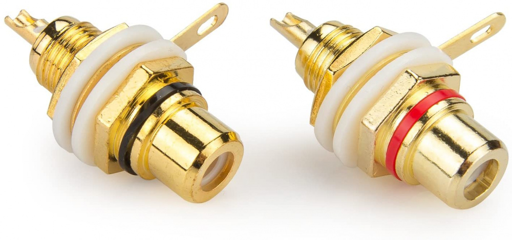
Here are non-isolated ground RCA jacks -
Isolated ground style jacks - crappy scratched up gold plating on these - PLUS they show the ground connector ring in the wrong place. It should be between the nylon washer & the nut to make sure it doesn't contact the case or panel. If you have this type, you'll need to run a separate ground wire back to the board.
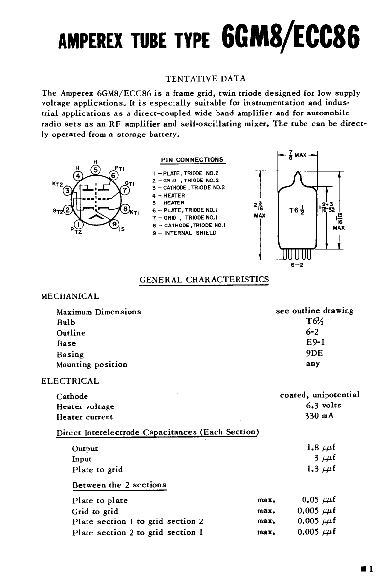
On an ECC86, pin 9 is an internal shield between sections, so use the heater supply jack for + & - 6 volts.
I'm not quite sure what R8/C2 are doing in this one. It has something to do with a balanced input, but that's as much as I can figure out. You'll see the grid of that section is tied to the -INP. They may be setting the bias of that triode? You start adding multiple semiconductors in there and I get lost pretty quickly.
My bad. It will use the 12au7 since I currently have a small stash of them and they appear to be much easier to find than the 6gm8 although, the 6gm8 do have a reputation for good sound. With the 12au7, center tap (I think) is pin9, heater supply - would need connected to -inp, which leads back to pin9 ... right?
The jacks are insulated, mounted on aluminum plate, which is then bolted in a wood chassis. This means I'll need to ground the shield to the star ground, correct? Would this be best at the potentiometer, board, or both, or by grounding both does this risk ground loops?
W/top on. Needs something to fill the empty space front right.
The articles said the mosfets would be fine w/out a heatsink except for one I recently ran across, and it was a write-up from the original designer. Going to recycle some old scrap slugs from work into small quarter size heatsinks. Hopefully this will be sufficient.
If I'm seeing this correctly, -INP leads to the grid of the 2nd triode section through R9, which is not referenced to ground. Ahhh...I just noticed something very similar to the Pass F6 I'll be building next. C2 & R8 are part of a feedback circuit. Notice how they connect to the junction between the output mosfets. Note, that's where your output is taken from. Nelson Pass explained arriving at this addition to his initial design in the writeup of the F6.
So...no, don't use -INP for the heater circuit. Take your Neg heater supply line to ground.
Since this is a balanced line input design, you'll have to figure out what to do with that -INP. It expects to see the inverse of +INP. I don't think you want to leave that hanging there with nothing attached, since that grid isn't referenced to ground. Maybe clip a 10k - 100K from that to ground just to test it.
Yep - goes right to pin 1 - the grid of Triode #2. You might want to ask about running this single ended on the DIY Audio tube forum. I'm curious if anyone has it set up that way. If you lived closer, I would loan you some input transformers and the problem might be solved.
Wow, the prices of unbalanced to balanced transformers. What about this small and <$20 tranny from Neutrik? Can't find anything on freq response. https://neutrik.com/en/product/nte1
"The original circuit is differential input. However, my layout grounds the negative input as standard to make the inout single-ended only. I normally wouldn’t make a simplification like this, however it avoids a very long and unsightly trace through the ground plane. Since I expect that SE-input is how most people would use it anyway this was an acceptable compromise for me (but of course it might not be for you 🙂 )."
(I think he meant to type input instead of "inout")
Then there's this -
"Important: As described in some of the diyaudio-posts I read about this design it has one major flaw and that is serious DC-offset at power-up and power-down. Both my boards are after adjustment within +/-10mV when they are fully warmed up and stabilised, but during power up they both swing the output to very close to one of the supply rails (meaning 20V or so) and stay for such a long time that I think it would be fatal for headphones. There are a couple of solutions to this, either an output capacitor or a delay circuit of some sort. I don’t have time to try either at the moment, but if you do so please report back."
As you've probably already seen, 6gm8s are getting pricy. I always liked the sound of the Svetlana 6n1p. I designed a 2A3 amp years ago that used one as the driver tube. The guy that bought the amp thought it was amazing that such a cheap Russian tube could sound so good.
KB - I found a little box of used 6DJ8s that I hadn't tested. I threw a few pairs into my simple linestage and these 2 pairs make music. No hiss, hum, or crackling from either pair.
The RCAs (made in Japan?) don't sound great at all. They have a very rolled off top end, but I figured you could use them for testing. They might be better when biased hotter than I'm running them, so they could sound fine in your project. The pair made in Holland do sound very good. Not sure how well these match in gain, but it will give you a good taste of the Bugle Boy 6DJ8 sound. PM me your address again and I'll drop them in the mail in the next few days.
Pair right? Pick which ones or I'll ship em' all.
Pair of EH steel pin, new, new production.
Pair of Mullard, one w/~3hrs other new, new production.
Pair of JJ steel pin, one w/~3hrs, other new, new production.
Single Tung-Sol, w/~2hrs, new production.
As I have yet to listen to any of the expensive tubes, I cannot comment on how they fare against those.
Curious to see what your take is on them but even the used ones are yet to be broken-in, so not sure how they may, or may not change, as they age.
You're going to have quite a few to compare! Those RCAs I included turned out to test good. Maybe they just need a different operating point than where I'm running them. My little linestage is just a simple SRPP.
My PS is just a brute force CRCRC with a solid state diode bridge. I think the caps are around 220uf and the resistors are 1600 ohms. The transformer is a center tapped 300v secondary - I'm only using one side, so 150v into the rectifiers. The top transformer is a dummy. It was part of a surplus lot, so I'm not sure what it really is. I know it didn't like 120v/60hz! There's a voltage divider to elevate the heaters about 50v above ground. I just used parts I had picked up from the local Rockwell/Collins surplus store. I wish that place was still open to the public, especially now that I know what I'm looking for.
I never thought this thing had that much gain. But I built it right after my first tube build - the Bottlehead Foreplay kit. That thing had GAIN - and right away too! Maybe my 6dj8 is all in the last 40% of the volume pot.
Heater wiring checked out. 6.4v using this The pins are so thin one broke off at the base while moving it around. Wasn't sure it would stay together, so ordered some of these just in case.
Nope, stepdown is in the heater circuit, that's all good. Heater circuit is independent of the board power supply. Something on the board +/-24v side, probably resistor but haven't narrowed it down yet.
Will have to look in the morning, but I think SGND-PGND is connected to lead5
_...and here is where I begin to edit yesterday's post. Sorry, I take some fairly strong headache meds and while they enable me to function, things get kind of foggy.
_
From Jim's Audio
_Firstly, for unbalanced, you can use either +INP or -INP. If -INP is used ( as mentioned in your message), the output is inverted phase. If this is your intend then no problem you can use this as the input. The inverted input terminals are the -INP pin that connects to R9, and SGND respectively. Another lead of R9 connects to pin 7 of the tube. When connecting this way, +INP need to be grounded or noise will be picked up at +INP terminal.
Alternatively, the non-inverting input terminals are +INP and SGND. When using this input, -INP need to be grounded. This is a must otherwise feedback cannot be accomplished and the amplifier gain is too high to be used.
_
So....after looking over the Application Notes on that power supply again, it's not a bipolar supply. There is no center "ground" and + & - on that one. It's either Pos voltage or Neg voltage. Bottom line - it just won't work for this project. If you had 2 of them, it would work. But that's expensive and serious overkill.
But did you get those bare transformers - the 24-0-24 (aka, 48v with a CT)? If so, this regulator board below should work just fine. Quick math - 24Vac * 1.41 = 33.84 - 1.4v (drop in 1n4007 bridge) - 1.5v (dropout voltage for LM317) = 30.94v. More than enough!
Oh - on that Bel power supply, Tab 5 is on the primary side and should not be connected to the output side. It is a tap off the transformer primary winding - meaning it's connected right to your wall outlet via a few turns of wire.
The 24v smps supplies the tube heaters and is reged to 6.5v. The Bel power supply, Haa24, has a +24, -24, and com, output. This is wrong for the +/- board supply? https://mouser.com/datasheet/2/643/ds_bps_linear_series-1314581.pdf Having separate power supplies was suggested in one of the write ups.
So, checked the connections on the +/-24 supply, and as far as I can tell, they were connected correctly. +24v to +vcc, -24 to -vcc and com to SGND/PGND. Voltage from supply hoovers around +/-23.8v. It seems odd connecting signal ground and power supply com at the same point.
Another thing I might have missed is the smaller drawing on the right side of the schem. Does only the heater +supply input go to both 1&2 and SGND-PGND1= pin9 connection, (pin9 connection is not labeled as SGND-PGND1, it is a different point than SGND/PGND) goes to -side of power supply, or connect as I had it with the +&- heater power supply driving input 1&2? I did not have pin9 connected to ground. If both +&- goes to 1&2, why does pin9 need grounded?
When connecting in normal polarity, if -inp needs to be grounded, as Jim's Audio mentions, and pin9 also needs grounded ... since SGND (-side of audio input) is also to ground, can I just jumper from these two points to the adjacent point connecting to the SGND trace? These connections are spaced closely together and it would be easy to jumper across all of them.
Then there is always the possibility the ebay purchases are not what they claim.
I found the correct data sheet - I was incorrect. That supply will be fine. Not the first time I've been wrong & certainly not the last!
Signal ground & PS common (or ground) are often the same. It's not Earth, like the green wire in the 120 AC line coming into the primary windings. It's the secondary side 0v point that everything else is referenced to. If you look at most tube schematics, you'll see all grounded components being tied to the - side of the PS caps in some way. Might be a run of bus wire snaking through the amp, or it could be a star ground point with lots of wires coming in from various stages.
On the heaters - you are correct to use 1 for POS and 2 for NEG on J5. Pin 9 on the 6dj8 is an internal shield between sections and the data sheets show no connection to the filament.
Yes, you can just connect all 3 of those points together since Pin 9 carries zero voltage or current...at least it shouldn't!
Comments
On the output jack ground - it depends on whether they are ground isolated jacks or not. If not, and they are on the same metal panel as the input jacks, ground will already be there, so only tie the shield of the output cable to the board ground.
Here are non-isolated ground RCA jacks -
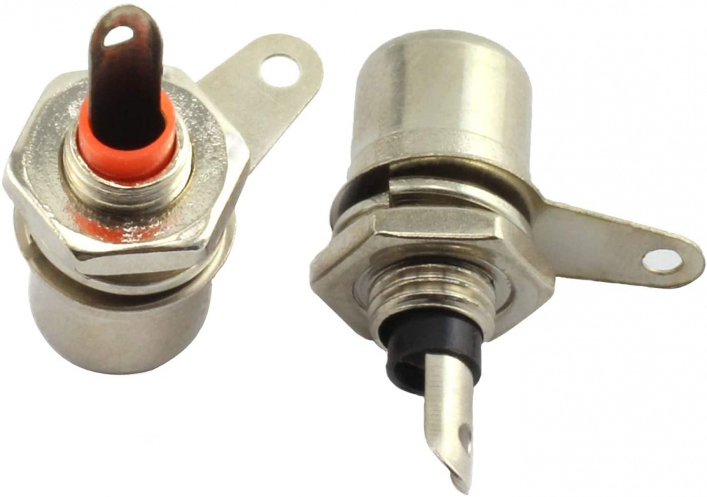
Isolated ground style jacks - crappy scratched up gold plating on these - PLUS they show the ground connector ring in the wrong place. It should be between the nylon washer & the nut to make sure it doesn't contact the case or panel. If you have this type, you'll need to run a separate ground wire back to the board.
On an ECC86, pin 9 is an internal shield between sections, so use the heater supply jack for + & - 6 volts.
I'm not quite sure what R8/C2 are doing in this one. It has something to do with a balanced input, but that's as much as I can figure out. You'll see the grid of that section is tied to the -INP. They may be setting the bias of that triode? You start adding multiple semiconductors in there and I get lost pretty quickly.
My bad. It will use the 12au7 since I currently have a small stash of them and they appear to be much easier to find than the 6gm8 although, the 6gm8 do have a reputation for good sound. With the 12au7, center tap (I think) is pin9, heater supply - would need connected to -inp, which leads back to pin9 ... right?
The jacks are insulated, mounted on aluminum plate, which is then bolted in a wood chassis. This means I'll need to ground the shield to the star ground, correct? Would this be best at the potentiometer, board, or both, or by grounding both does this risk ground loops?
Do the remaining connections look correct?
W/top on. Needs something to fill the empty space front right.

The articles said the mosfets would be fine w/out a heatsink except for one I recently ran across, and it was a write-up from the original designer. Going to recycle some old scrap slugs from work into small quarter size heatsinks. Hopefully this will be sufficient.
Do the transformer covers look to gaudy?
If I'm seeing this correctly, -INP leads to the grid of the 2nd triode section through R9, which is not referenced to ground. Ahhh...I just noticed something very similar to the Pass F6 I'll be building next. C2 & R8 are part of a feedback circuit. Notice how they connect to the junction between the output mosfets. Note, that's where your output is taken from. Nelson Pass explained arriving at this addition to his initial design in the writeup of the F6.
This is interesting reading and I learned quite a bit - https://www.firstwatt.com/pdf/art_f6_baf.pdf
So...no, don't use -INP for the heater circuit. Take your Neg heater supply line to ground.
Since this is a balanced line input design, you'll have to figure out what to do with that -INP. It expects to see the inverse of +INP. I don't think you want to leave that hanging there with nothing attached, since that grid isn't referenced to ground. Maybe clip a 10k - 100K from that to ground just to test it.
Now even more confused but do have the +output confirmed.
Though I posted a pic of the board underbelly, maybe this will help. 3 pins surrounding -inp.
Yep - goes right to pin 1 - the grid of Triode #2. You might want to ask about running this single ended on the DIY Audio tube forum. I'm curious if anyone has it set up that way. If you lived closer, I would loan you some input transformers and the problem might be solved.
Dad always told me I could bend a crowbar in a sandbox ... and now the duh moment.
From add copy, "The input tube can be the popular ECC86/6GM8 or E88CC". Where did I get the 12au7 would work???
It also says, "The input can be configured as either balanced input, or unbalanced input" but doesn't say how.
Wow, the prices of unbalanced to balanced transformers. What about this small and <$20 tranny from Neutrik? Can't find anything on freq response. https://neutrik.com/en/product/nte1
Hammond $50 https://mouser.com/datasheet/2/177/560-1389877.pdf
From theslowdiyer.wordpress.com -
"The original circuit is differential input. However, my layout grounds the negative input as standard to make the inout single-ended only. I normally wouldn’t make a simplification like this, however it avoids a very long and unsightly trace through the ground plane. Since I expect that SE-input is how most people would use it anyway this was an acceptable compromise for me (but of course it might not be for you 🙂 )."
(I think he meant to type input instead of "inout")
Then there's this -
"Important: As described in some of the diyaudio-posts I read about this design it has one major flaw and that is serious DC-offset at power-up and power-down. Both my boards are after adjustment within +/-10mV when they are fully warmed up and stabilised, but during power up they both swing the output to very close to one of the supply rails (meaning 20V or so) and stay for such a long time that I think it would be fatal for headphones. There are a couple of solutions to this, either an output capacitor or a delay circuit of some sort. I don’t have time to try either at the moment, but if you do so please report back."
Any recommendations on affordable 6dj8/6922/ecc88/e88cc/6n1p or 6gm8 tubes?
As you've probably already seen, 6gm8s are getting pricy. I always liked the sound of the Svetlana 6n1p. I designed a 2A3 amp years ago that used one as the driver tube. The guy that bought the amp thought it was amazing that such a cheap Russian tube could sound so good.
KB - I found a little box of used 6DJ8s that I hadn't tested. I threw a few pairs into my simple linestage and these 2 pairs make music. No hiss, hum, or crackling from either pair.
The RCAs (made in Japan?) don't sound great at all. They have a very rolled off top end, but I figured you could use them for testing. They might be better when biased hotter than I'm running them, so they could sound fine in your project. The pair made in Holland do sound very good. Not sure how well these match in gain, but it will give you a good taste of the Bugle Boy 6DJ8 sound. PM me your address again and I'll drop them in the mail in the next few days.
Swap? Due to my inattentiveness, it appears I have some extra new production Muillard, JJ, EH 12au7.
Sure, I'd like to hear one of those new versions and it just so happens the driver board on my ST-70 runs 12au7s!
Pair right? Pick which ones or I'll ship em' all.
Pair of EH steel pin, new, new production.
Pair of Mullard, one w/~3hrs other new, new production.
Pair of JJ steel pin, one w/~3hrs, other new, new production.
Single Tung-Sol, w/~2hrs, new production.
As I have yet to listen to any of the expensive tubes, I cannot comment on how they fare against those.
Curious to see what your take is on them but even the used ones are yet to be broken-in, so not sure how they may, or may not change, as they age.
https://midwestaudioclub.com/diy/discussion/1519/bravo-tube-head-amp-mod#latest
I would love to hear the new Mullards, so I'll make it worth your while! Let me see what I can match up for nice strong pair of 6DJ8s.
They're a $20 tube and you've already sent me way more stuff than that. Don't worry bout' it.
Trying a new vendor. One pair of nos Tesla 6dj8, JJ e88cc, and Voskhod 6n1p from thetubestore.com.
You're going to have quite a few to compare! Those RCAs I included turned out to test good. Maybe they just need a different operating point than where I'm running them. My little linestage is just a simple SRPP.
That is a really good, low distortion, circuit for the 6DJ8 tube IF you need that much gain.
What did you do for the power supply?
My PS is just a brute force CRCRC with a solid state diode bridge. I think the caps are around 220uf and the resistors are 1600 ohms. The transformer is a center tapped 300v secondary - I'm only using one side, so 150v into the rectifiers. The top transformer is a dummy. It was part of a surplus lot, so I'm not sure what it really is. I know it didn't like 120v/60hz! There's a voltage divider to elevate the heaters about 50v above ground. I just used parts I had picked up from the local Rockwell/Collins surplus store. I wish that place was still open to the public, especially now that I know what I'm looking for.
I never thought this thing had that much gain. But I built it right after my first tube build - the Bottlehead Foreplay kit. That thing had GAIN - and right away too! Maybe my 6dj8 is all in the last 40% of the volume pot.
About ready ... not.
Heater wiring checked out. 6.4v using this The pins are so thin one broke off at the base while moving it around. Wasn't sure it would stay together, so ordered some of these just in case.
... and smoke.
$hit.
The step down board fried? Those use an LM317, right? Those are good for 1.5A. What was your input voltage?
Nope, stepdown is in the heater circuit, that's all good. Heater circuit is independent of the board power supply. Something on the board +/-24v side, probably resistor but haven't narrowed it down yet.
Will have to look in the morning, but I think SGND-PGND is connected to lead5
_...and here is where I begin to edit yesterday's post. Sorry, I take some fairly strong headache meds and while they enable me to function, things get kind of foggy.
_
From Jim's Audio
_Firstly, for unbalanced, you can use either +INP or -INP. If -INP is used ( as mentioned in your message), the output is inverted phase. If this is your intend then no problem you can use this as the input. The inverted input terminals are the -INP pin that connects to R9, and SGND respectively. Another lead of R9 connects to pin 7 of the tube. When connecting this way, +INP need to be grounded or noise will be picked up at +INP terminal.
Alternatively, the non-inverting input terminals are +INP and SGND. When using this input, -INP need to be grounded. This is a must otherwise feedback cannot be accomplished and the amplifier gain is too high to be used.
_
So....after looking over the Application Notes on that power supply again, it's not a bipolar supply. There is no center "ground" and + & - on that one. It's either Pos voltage or Neg voltage. Bottom line - it just won't work for this project. If you had 2 of them, it would work. But that's expensive and serious overkill.
But did you get those bare transformers - the 24-0-24 (aka, 48v with a CT)? If so, this regulator board below should work just fine. Quick math - 24Vac * 1.41 = 33.84 - 1.4v (drop in 1n4007 bridge) - 1.5v (dropout voltage for LM317) = 30.94v. More than enough!
https://www.amazon.com/SMAKN®-Supply-Adjustable-Module-Converter/dp/B011BDP004/ref=pd_sbs_2?pd_rd_w=sev0F&pf_rd_p=965b754e-4670-4322-863d-d4929773ec49&pf_rd_r=YCP9W0SS6G0Y7QEC1JSX&pd_rd_r=4e5a32ef-fb74-4eda-bd05-15fbf62c5870&pd_rd_wg=Brx8W&pd_rd_i=B011BDP004&psc=1
Oh - on that Bel power supply, Tab 5 is on the primary side and should not be connected to the output side. It is a tap off the transformer primary winding - meaning it's connected right to your wall outlet via a few turns of wire.
Read your reply after typing this one.
The 24v smps supplies the tube heaters and is reged to 6.5v. The Bel power supply, Haa24, has a +24, -24, and com, output. This is wrong for the +/- board supply? https://mouser.com/datasheet/2/643/ds_bps_linear_series-1314581.pdf Having separate power supplies was suggested in one of the write ups.
So, checked the connections on the +/-24 supply, and as far as I can tell, they were connected correctly. +24v to +vcc, -24 to -vcc and com to SGND/PGND. Voltage from supply hoovers around +/-23.8v. It seems odd connecting signal ground and power supply com at the same point.
Another thing I might have missed is the smaller drawing on the right side of the schem. Does only the heater +supply input go to both 1&2 and SGND-PGND1= pin9 connection, (pin9 connection is not labeled as SGND-PGND1, it is a different point than SGND/PGND) goes to -side of power supply, or connect as I had it with the +&- heater power supply driving input 1&2? I did not have pin9 connected to ground. If both +&- goes to 1&2, why does pin9 need grounded?
When connecting in normal polarity, if -inp needs to be grounded, as Jim's Audio mentions, and pin9 also needs grounded ... since SGND (-side of audio input) is also to ground, can I just jumper from these two points to the adjacent point connecting to the SGND trace? These connections are spaced closely together and it would be easy to jumper across all of them.
Then there is always the possibility the ebay purchases are not what they claim.
I found the correct data sheet - I was incorrect. That supply will be fine. Not the first time I've been wrong & certainly not the last!
Signal ground & PS common (or ground) are often the same. It's not Earth, like the green wire in the 120 AC line coming into the primary windings. It's the secondary side 0v point that everything else is referenced to. If you look at most tube schematics, you'll see all grounded components being tied to the - side of the PS caps in some way. Might be a run of bus wire snaking through the amp, or it could be a star ground point with lots of wires coming in from various stages.
On the heaters - you are correct to use 1 for POS and 2 for NEG on J5. Pin 9 on the 6dj8 is an internal shield between sections and the data sheets show no connection to the filament.
Yes, you can just connect all 3 of those points together since Pin 9 carries zero voltage or current...at least it shouldn't!