Home ›
Site Links
Howdy, Stranger!
It looks like you're new here. If you want to get involved, click one of these buttons!
Quick Links
Categories
In this Discussion
Who's Online (0)
What response splicing tool do you use?

I'm comparing the features and capabilities of various methods of response splicing, looking at all the tools available to do this task. I currently have the following options:
SoundEasy
Omnimic
REW
ARTA
VituixCAD
FRD Response Blender and Minimum Phase Extractor spreadsheet
Are there other tools available that anyone here uses that isn't in the list above?
I'm not deaf, I'm just not listening.
Comments
I've used HolmImpulse in the past. Like REW you have to import a simulated baffle step response to add to the nearfield measurement.
I didn't even know you could splice in ARTA or Holm.
Or OmniMic
Thanks, added Holm to the list.
FWIW splicing in ARTA is pretty basic and clunky. Set one frequency response as an overlay, the other is the active response. Set the cursor at the frequency you want to splice. In the frequency response window, edit menu, then you have selections to merge response with overlay above or below the cursor. It does a hard cut at the frequency selected for both frequency response and phase. Two big problems is ARTA won't show phase for overlay responses so making adjustment for phase alignment is pretty much out of the question. Other problem is ARTA won't load a regular ass FRD file as an overlay, so processing near-field response for diffraction is pretty much out of the question.
In Omnimic, you load 2 responses to the "add curves" list. It will try to automatically pick a splice point which I think is pretty dicey, so the recommended procedure would be to limit the frequency range of each response to force splice point. In the curve setting window there's a button "save spliced to another" which splices the loaded curves together and saves to a new file. Only works with 2 curves in the list, and of course processing near-field response for diffraction would need to be done with other software. Has options for level and phase adjustment of each response which is nice, and software is free download, Omnimic purchase not required")
Most will retain measured phase, only exception at this point appears to be the FRD Response Blender spreadsheet which forces minimum phase calculation so measured phase is thrown away.
(Spoiler - VituixCAD is by far and away the most functional and featureful option. )
Phase is going to be inaccurate after the splice unless you are saying that the low frequency phase is overwritten by these programs
Maintaining measured phase only applies to far field measurement. Near field should be delay adjusted to match. Nothing to be overwritten, only delay added or subtracted.
For feature comparison relating to phase only:
Soundeasy - splice keeps both low and high frequency portion phase, adjustment to delay is manual process.
Omnimic - splice keeps both low and high frequency portion phase, adjustment to delay is manual process, but easy.
REW - Merge keeps phase of high frequency portion, low frequency portion is automatically adjusted to match.
ARTA - splice keeps both low and high frequency portion phase
Holm - Includes checkbox to "match phase before stitching" so low frequency portion is delay adjusted to match far field phase.
VituixCAD - low frequency portion phase is automatically adjusted to match far field phase. Delay value available for manual adjustment if warranted. Output can be measured phase or minimum phase by the click of a button. If min phase is selected, HBT slope is automatic by slope at end of response.
FRD Response Blender - Min phase only, measured phase is not used. HBT slope is manual entry.
For maintaining measured phase, REW, Holm, or VituixCAD are best options since process is automatic. Omnimic is runner up with manual but easy process.
I use Response Modeler, the program Jeff wrote before the Blender.
InDIYana Event Website
So did I, but man that thing is clunky. Obviously it works as lots of us have built many great sounding speakers using it as our sim tool. But Jeff's Blender is so much cleaner. Just like Dave's WinPCD is compared to the old Excel PCD.
I don't like the Blender GUI, or that it can be the only Excel sheet open to extract phase, nor do I prefer WinPCD since I can't do series xovers with it. It really should have that utility.
InDIYana Event Website
For response splicing, I have used OmniMic, FRD Response Blender, and VituixCAD. The VituixCAD diffraction and merger tools seem to be the best. The only thing that I do not like about VituixCAD is that the diffraction tool step response adjustment curve is with respect to a fixed microphone distance and height. So if I set the microphone at tweeter height at a distance of, say, 2.5 meters, then the step response model is quasi-anechoic from about 1kHz down to 5Hz or so. But this is not what I want. I want my model to include the floor boundary reinforcement effect. So if I place the center of my woofer 17" above the floor (as opposed to 6" or 24", etc.), I want the model to reflect this so that I can properly adjust my crossover components to compensate (ie., employ the proper BSC curve).
The only tool that I know of that can do this is Jeff Bagby's BDBS spreadsheet. One quadrant of this spreadsheet includes the Allison equations, which are a set of power response equations that Roy Allison developed using a multi-mic measurement technique. If I set the side wall and front walls to infinity, I can model any woofer to floor distance and save the model as an FRD file. Then I need to sum this to my VituixCAD diffraction model before performing the final NF/FF/step response merge.
What the hell is a splicing tool?
"Allison effect" might have been news in 1965, but today it's pretty basic acoustic knowledge and an over-simplification of in-room response. Today we can read all about "speaker boundary interference response", or the in-room bass response, modern terms for the same thing.
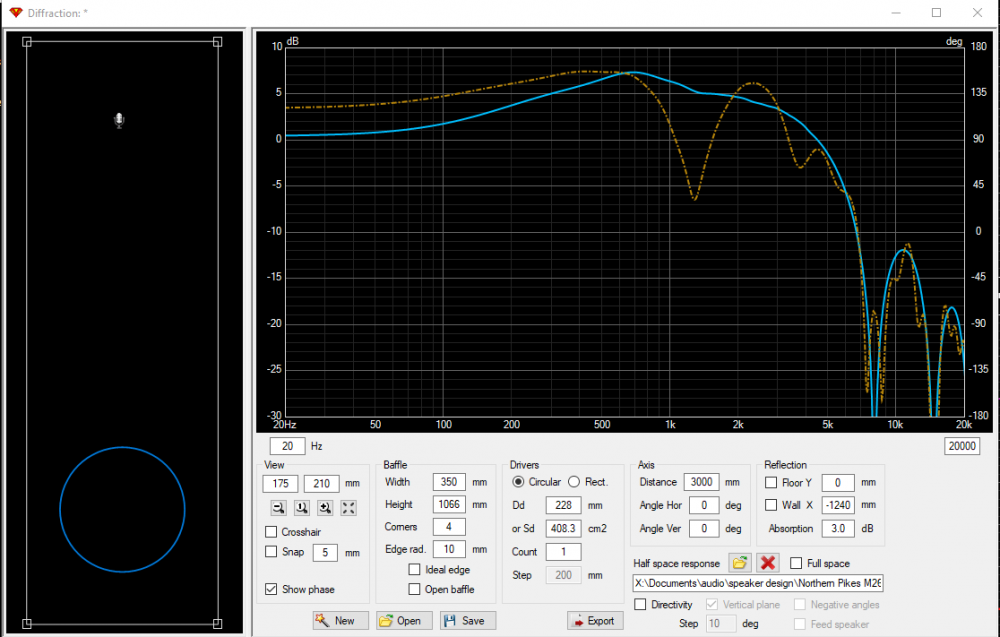
Main problem with floor boundary is the reflection is a moving target with listening distance and height, so you have to choose a listening location if you want to address it completely. FWIW VituixCAD does include the ability to include reflections for the diffraction simulation. For example below, some rectangular speaker located 8.25" above ground. The orange trace is with the floor reflection included, and amplitude adjusted for same peak amplitude as the result without reflection. Difference here at 3m listening distance is about 3dB at the low frequencies.
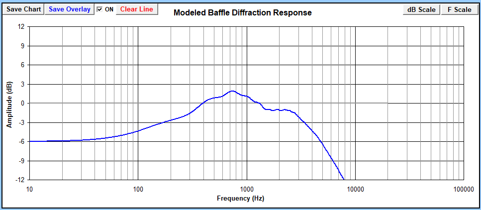
Using BDBS, same speaker and same mic distance selected, mic height in not directly adjustable so I included an angle of 13 degrees to locate the mic at listening height. Looks rather similar to the diffraction response from VituixCAD:
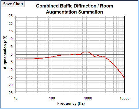
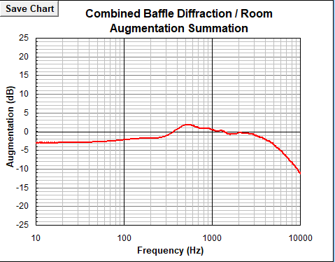
For the room boundary, I set the height above floor to the same y axis height for the speaker, and distance from rear and side walls set to 10000in to effectively remove them from the equation to avoid the extra mess they provide. Combined diffraction and room augmentation shows 3dB of baffle loss instead of 6dB. Rather similar result at low frequency, though the boundary reinforcement misses the reflection interference higher up in frequency.
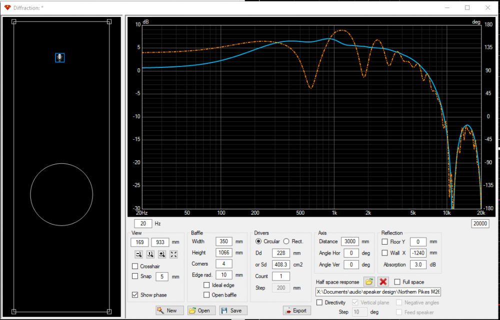
Same comparison, but now the speaker is moved up from 8.25" to 17". VituixCAD:
In BDBS we have same agreement in response shape, though only up to about 300Hz or so because of the lack of reflection interference.
BDBS boundary reinforcement sim doesn't fully give back 6dB step until speaker is at 3ft height which I'm not sure is the correct mentality for BSC design criteria. Admittedly, incorporating boundary reinforcement into a speaker design can be complex, however we have modern tools to evaluate in-room response, boundary interference, and can even simulate crossovers in digital domain to make sure the tonal balance is just right before placing a parts order, as well as apply room EQ to assist with the low end response effects in any room. It's a wonderful time to live in for audio nerds")
IT USED to be --> https://duckduckgo.com/?q=audio+tape+splicer&atb=v350-1&iax=images&ia=images
Same concept here only in the digital data domain . . . chopping two FR data files-off at a common point and joining them to make a full spectrum FR file.
That is my conclusion as well. BDBS seems to indicate that the woofer to floor distance needs to be at least 3 feet before you would need to apply the full 6dB of BSC (assuming 10000in distance for the other walls). A woofer to floor distance of about 2 feet would need about 5dB of BSC. A distance of about 8 to 17" would need about 3dB of BSC. Etc. What I am trying to do is to come up with a quick and easy way to incorporate the average floor boundary effect into my model. Then I can "pound the response flat" in VituixCAD with crossover parts to achieve a neutral tonal balance. Using VituixCAD alone, I have had difficulty setting up the model to include the floor boundary, because the response tends to bounce around a great deal with different microphone distances and heights.
Another thing to consider, is inclusion of boundaries or allison effect is turning the response result closer to "in-room" than anechoic response, in which case target slope should be more like -0.7dB/oct than a flat line. With that slope skew on the diffraction / boundary effects, full BSC I think should be perfectly okay down to at least 2ft. The 3-way speaker I have at my TV has an 8" woofer at 2ft height, full BSC and I think it's perfect, though YMMV and there's personal preference in the mix as well.
Somewhat related, is that VituixCAD diffraction simulator calculation is a bit different than BDBS as well. VituixCAD is a bit more sensitive to distance, while BDBS provides full 6dB regardless of mic distance selection. What Kimmo has mentioned is that 1m measurement distance is often capturing a bit less than the full diffraction effect at the listening distance, so recommendation is to use a far distance of 10meters for diffraction simulation for applying to nearfield response, to provide a bit of compensation, and ensure proper balance overall when the response is filtered down to a flat response, avoiding a speaker that sounds too thin.
I did a diffraction modeling comparison of VituixCAD verses BDBS using my Zonker speakers as an example. Baffle is 10" x 15.5" with 3/4" roundovers and an 8 inch woofer. As part of the test, I summed the BDBS diffraction model with the Allison floor boundary quadrant and then looked at how this affected the summed curve at various woofer to floor distances. I also compared these results with the VituixCAD model to see if I could replicate the Allison floor boundary effect by adjusting VituixCAD's microphone distances, heights, or reflection(floor) settings.
Here is the basic VituixCAD diffraction model for my Zonker speakers:
Here is the same diffraction model, this time using Jeff's BDBS speadsheet. Note that I am showing the diffraction as a gain of 6dB, not a loss of 6dB:
Here is a comparison overlay of the two diffraction models. They are fairly close, but I can see a little variation in the overall slope for some unknown reason. Probably no bid deal.
Here is the BDBS diffraction model summed with the Allison floor boundary curve in the case where the Zonker speaker is sitting on the floor. The center of the woofer is 5 inches above the floor. Note that the other boundaries (side walls, etc) have been set to infinity (999999) so I can see the effect of the floor alone. Also note that I have shut off the room gain quadrant as well. The summed curve is almost a flat line, indicating that no BSC is needed when the speaker is placed on the floor.
Here is the same summed curve, but with the Zonker speaker sitting on top of a 7 inch high stand. This would place the center of the woofer cone 12 inches above the floor. In the summed curve, notice how the Allison dip moves over to a spot half way between 100 and 1000Hz. This is not an easy problem to fix in the crossover.
Here is the same summed curve, this time with my Zonker speaker sitting on a 24" high stand. This is how the speaker will actually be used in the field. Now the Allison dip moves down to 175Hz and creates a situation in which, if you apply the full 6dB of BSC, the gain below 100Hz will be too high.
Finally, I created a curve comparing the BDBS diffraction curve to the summed Allison curve at a woofer height of 29" (24" high stand). I tried to replicate the Allison summed curve in VituixCAD by reducing the microphone distance from 2500mm to 300mm, and adding floor reflections, but I could not get a good match.
Comparison should really be, which matches reality the closest? I mentioned previously, VituixCAD is more sensitive to distance, at 2500mm it's showing a bit less baffle step than BDBS, which I would suspect is a bit closer depiction of reality. You may get closer agreement setting distance in VituixCAD to 10m+. One issues in BDBS is that baffle loss will be full 6dB regardless of mic distance, as long as distance is >1ft.
Main concern I see is the mic location in VituixCAD. If you've left it on axis with the woofer, you are effectively simulating the reflections with your head on the ground. Main reason why in my comparison above, mic location is at listening height. In any case, main purpose of reflection features in VituixCAD is not to for boundary reinforcement, but just to show where obvious interference will occur based on listening distance and speaker location.
Again, real question would be, how representative of reality is that "Allison" response? Can you measure anything in-room that resembles it?
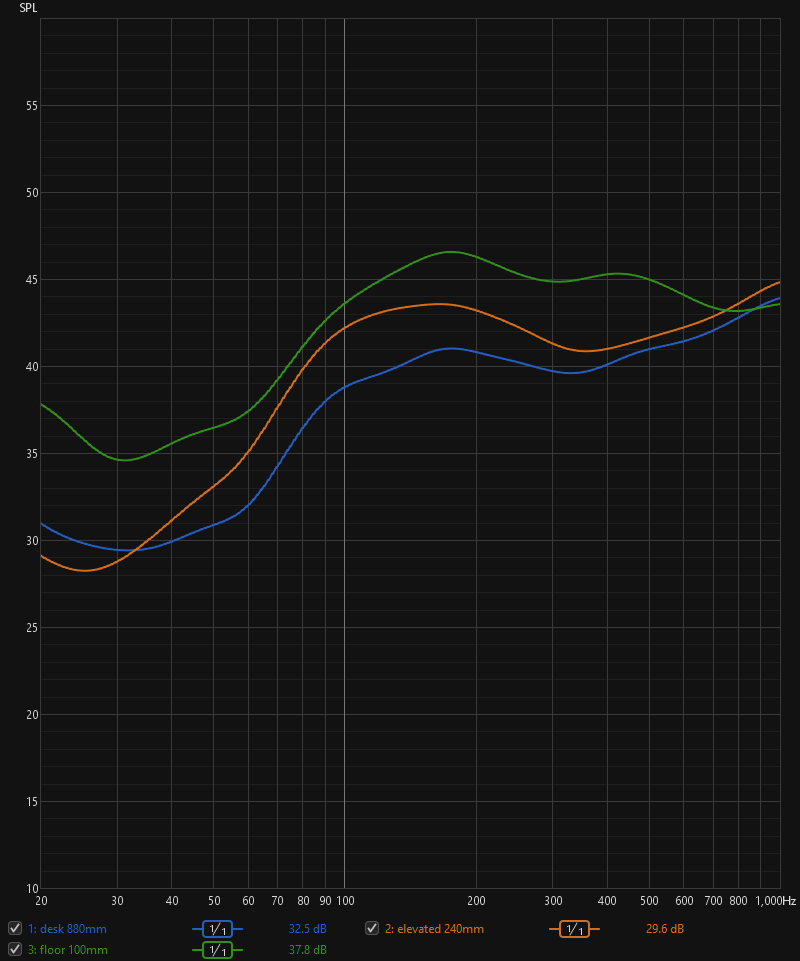
Here's a quick and dirty evaluation I did in my office space. I used a cheap little computer sized speaker here, 4L box with Dayton DA115. It doesn't do much <100Hz, but for baffle step balance, I would be most interested in the output from 100-500Hz range. I did a "moving mic" room average to measure the room response, no different than you would for setting up room EQ. Mic is about 1.7m from the speaker, which in my office is about 2/3 of the way through the room, and the speaker is a generous 70cm from the back wall, measured to the front baffle. Floor is vinyl plank on top of concrete, and a thin rug is in the middle where my desk chair sits, woven rug, not carpet.
I compared placing the speaker on the floor directly (woofer center 10cm to floor), elevating it slightly (24cm), and placing at desk height (88cm), normal listening height. I also calculated SPL loss over distance, since the speaker on floor level will be further from the mic (about 30cm), and compensated the measured SPL at listening height by 1.5dB accordingly, and the elevated response by 0.5dB. I used heavy 1/1oct smoothing to get an idea of the relative change in SPL without much room reflection wiggles.
Here's the result:
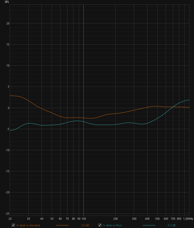
Next, to show just the difference between these elevations, I divided the desk height by the other two. What I think this shows is that with a woofer right at floor level, only 10cm from the floor, there is a 4dB difference, so 2dB BSC is appropriate. Elevating only 24cm, BSC of 4dB is appropriate.
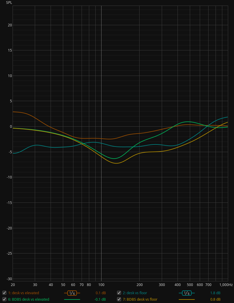
For BDBS comparison of above, I entered in the floor, rear wall and side wall to match the room I'm in. Traced the response "combined diffraction / room augmentation" response at each elevation, and then imported to REW, same division steps as above, same 1/1 oct smoothing. It doesn't match real in-room measurement very well I would say, so I don't put much trust in it.
Thanks for the test data. Looks somewhat inconclusive. Some of my personal "in room" measurements, made over the years, seem to be consistent with the Allison effect. With all of my stand mount speaker systems (woofer about 30" above floor), I have always measured a huge 3-5dB bouncing type "dip" in the 80 to 300Hz region, which is consistent with the Allison effect. I have also taken measurements at various heights, similar to your test above, and have always noticed that the SPL increased more and more in the 80 to 300Hz region, compared to the 300-1kHz region, as I lowered the speaker closer to the floor. My guess is that the Allison effect is real, but I have no way to prove it. I have been reading and re-reading Roy Allison's papers on the subject, but, so far, have been unable to find the details of how he actually performed his measurements (i.e, number of measurements, microphone locations, etc.). All I know is that he used a multi-mic technique in a variety of typical listening rooms.
I can't reproduce anything that BDBS spits out for room boundaries with confident correlation. The "allison effect" misses too much of real room boundary interference, so the conclusion I've come to is basically what I've stated above. 2dB BSC for right on the floor, small elevation 4dB, everything else 6dB, and room EQ to assist with overall room response beyond that. YMMV but that's my thought process for now. It's easy enough to reproduce the above set of measurements in-room for any speaker for evaluation through design phase. For room interaction, REW's "room sim" section provides good data for the room interference, without a bunch of furniture and other stuff in it anyway.
So, lets assume this is correct and this is an objective fact. Subjectively, is one of these better than the other?
1) Right on the floor would allow you to have a higher sensitivity speaker. If you don't have plenty of power on hand, this could be good. Any other reasons this would be beneficial?
2) I think having the woofer right on the floor avoids floor bounce which is beneficial. Is that right? Any negatives?
3) Other reasons that one of the choices is "better" than the others?
To state the obvious, subwoofers benefit from being on the floor for the same reason, a boost in output capacity is always welcome. For woofers playing further up in frequency, from the simple test above, the behaviour of the driver slightly elevated I think is more predictable, given the expected shape of "baffle step":
Placing the woofer right at floor level, probably makes the speaker a bit more sensitive to the room it's in. Not all floors are the same, so there's varying levels of absorption coeffiecients at play that may affect the overall sound through the mid-bass range.
I wouldn't place the "floor bounce" too high on the priority list, there's plenty of other bounces at play for room interaction. For a midrange up at listening height, lowest interference frequency from the floor will be in 200-300Hz range, so logic would say to set the crossover around 400Hz and that first "bounce" is avoided. In the grand scheme of things I don't think it's that important, there's plenty of other reflections just around the corner.
Main concern with the woofer at the floor for me is a couple things. First is the distance between woofer and midrange, and second is distance from each individual speaker to the listener. A wide separation between drivers means that the speaker will have a "proximity effect", and best sound will be at a far listening distance, or at least farther than what is acceptable for many speakers. At close range, expect bass to be a bit thin if the speaker has good balance at a far listening distance, so this may not suit many smaller listening spaces very well, or need additional EQ to correct for the space.
That said, I do enjoy the speakers I've built with low woofers very much, even though it can be a bit more of a challenge to get the balance right, I like a good challenge")
My family room is not overly large (14' x 22') so I've never felt the need to mount my woofers down by the floor for any bass gain. I like keeping my driver spacing close because the room arrangement is not ideal (it's not a dedicated listening room).
This is purely subjective, I was working on a project that had a single woofer in a bass bin right by the floor and the MT up at ear level, don't remember exactly where the xo point was, probably 400-500 Hz. To my ears the bass was fine as was the midrange and treble, but the midbass was pretty muddy sounding. I turned the bass bin over so the woofer was right below the MT and remeasured/modified the xo. Night and day midbass difference. YMMV
It may be worth a mention, measurements at tweeter axis only will inherently be problematic for design, for the same proximity effect reason I mentioned above, the relative distance between drivers will have a significant SPL difference at the mic. One bandaid solution for this type of measurement would be to calculate relative SPL difference and adjust the measured response SPL accordingly.
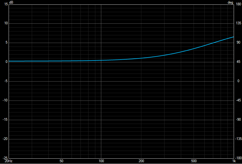
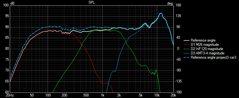
An example for the speaker in the photo on the right above. Response comparison at 1m (soilid white) vs 2m (blue dashed), if I had balanced for flat response with 1m measurement at tweeter level, speaker would be a bit bloated at real listening distance.
For the nearfield / boundary problem, I have had the idea to use a heavily smoothed in-room averaged RTA measurement as above instead of nearfield measurement for the bass response for merging. Haven't done that comparison yet, maybe something to play with in the future..