Site Links
Howdy, Stranger!
It looks like you're new here. If you want to get involved, click one of these buttons!
Quick Links
Categories
Who's Online (0)
Minimum phase is a waste of time :p

This is just a little write up on why minimum phase calculations and Hilbert-Bode Transform can and should be avoided when processing measurements for crossover design.
https://drive.google.com/file/d/1dq7mLeQMint8V95oJ1i6GXxyYRFfCgXG/view?usp=share_link
This, along with my other document detailing the difference between single and dual channel measurements, should make it clear why this is my recommended process, and with VituixCAD in mind, why the instructions call for dual channel measurements and do not detail any minimum phase processing between measuring and processing the response data.
My other supporting documents (VituixCAD oriented) can be found here. Hopefully someone finds them useful.
https://drive.google.com/drive/folders/1KDyECkAIVAuNEtKVobKmsfvtFczGqOQw?usp=share_link
Any feedback is welcome, I will update the document if something is not clear and needs more detail or rewording, or if something is incorrect.
Happy Holidays ![]()


Comments
I appreciate your input on this topic. There is a lot of discussion / articles presenting the pros and cons of differing approaches. Perhaps it depends upon the order of crossover employed i.e. First Order vs everything else?
No, it doesn’t. Difference is only measured phase vs calculation, the shape of the filter transfer function is irrelevant. I found very little validation when looking at other discussions around this topic, so I completed my own validation. Steps completed here for validation can be reproduced by anyone, and I encourage it in fact. The point the document attempts to make clear is that your measurements contain perfectly good phase information, don’t throw it away and replace it with calculated phase in places where you don’t need to.
This is one statement (PassLabs article) I saw that raised the question (for me) of crossover order. ‘Of all these filters only one, the lowly 6dB/octave crossover has both accurate amplitude and phase response when the outputs are reassembled.’
And others (no surprise from white papers by first-order speaker manufacturers) that draw similar conclusions re all other filter topologies - where phase cannot be corrected.
As such minimum phase is otherwise unobtanium and agree is hence, as your research shows, ‘a waste of time’.
Perhaps a wrong conclusion. But an interesting concept to look into further.
I think you may be misunderstanding the intent of this document, which is simply the accuracy of the measured data when applied to simulation software, which is separate from the phase interaction of crossover filters and the "time alignment" of the final speaker.
Never say never. FIR filtering in digital domain can do pretty much anything you can imagine.
See comment above. Nothing to do with the the investigation in this document. In any case, to diverge a bit from topic, the "time alignment" of the final speaker is most easily observed in the step response. In VituixCAD, just go to view - Impulse Response, and check the box for step response. You will find that lower order filters provide low time delay, so step response is improved. High order filters will have poor step response, best to be avoided if you can help it at low frequencies due to the group delay added to the system. Easiily shown by simply loading some data into VituixCAD and applying some active filter blocks and viewing the result. Of course both ARTA and REW will show you the step response of your real world measurements as well, and APO EQ operates perfectly well as a crossover simulator.
Problem with 6db/oct filter slope is the requirement for very special drivers and attention to other details to avoid other issues in distortion, breakup, power response..So 3rd-4th order acoustic rolloff is usually the compromise.
Concerning filters and Group Delay: the same can be visualized in WinISD by applying filters to a modelled driver and then opening the Group Delay graph - gets ugly the more filters added which keeps me looking for sealed driver alignments even when using DSP.
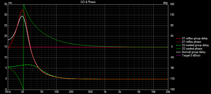
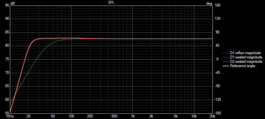
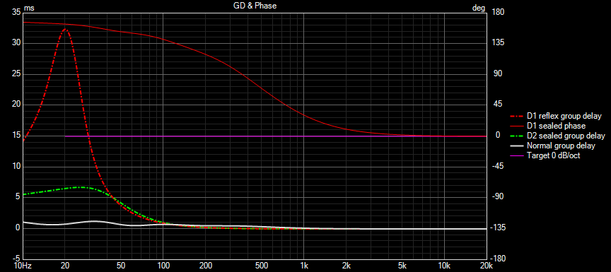
FWIW whether sealed or ported, group delay is dependent on the response of final response. A Sealed box with DSP EQ to match the response of a ported box, will have the same group delay as the ported box.
Here's the comparison. I took the same driver, simulated in ported and sealed cab, dashed lines as shown. Then, applied EQ to the sealed cab to closely match the ported cab, solid line.
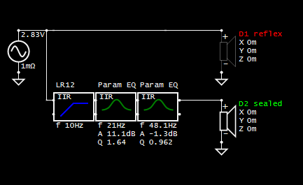
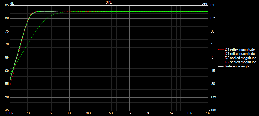
Comparing group delay, the ported cab is red dashed, the sealed cab is green dashed, and the sealed cab with EQ is solid white.
^ This is awesome info but I didn't mean that I was trying to use a sealed alignment to emulate a ported one.
I just look for drivers that will play well in a sealed alignment and use DSP for the PEQ and XO application to satisfy my ears in my space.
(You are a machine, man!).
I understand, the takeaway is that the resulting group delay of the system will include the effects of the EQ, I just wanted to make sure you didn't think that sealed box + EQ would have the same group delay of the sealed box without EQ.
Ported boxes are more difficult for me to get right with PEQ/XO via DSP than sealed - I suspect that it has a lot to do with Group Delay.
Ported woofers just sound like they are out of sync for some reason . . .
Does PEQ have the same effect on a drivers' GD as a steep XO?
Steep slope is steep slope no matter how you implement it.
Bah!
No free lunch anywhere . . .
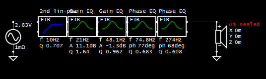
FIR filters can work well to "fix" group delay, but at the expense of total delay, so sync with video for HT may be problematic. For music though...
I am all about the music - the HT is fine as it is - just entertainment/not critical.
Tell me more about the music aspects . . .
Same as above, but with FIR filters.
dcibel
My feedback was in agreement with your findings, as I found your conclusion of interest.
I imagined a first order crossover, where phase is ~congruent, unlike any other, and merely raised this crossover as per its unique characteristics.
I'm sorry but I don't follow the relation between the crossover and this topic.
Continuing completely off-topic view of crossover order.
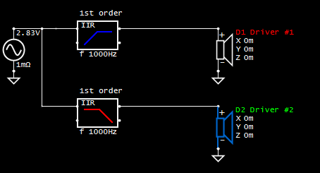
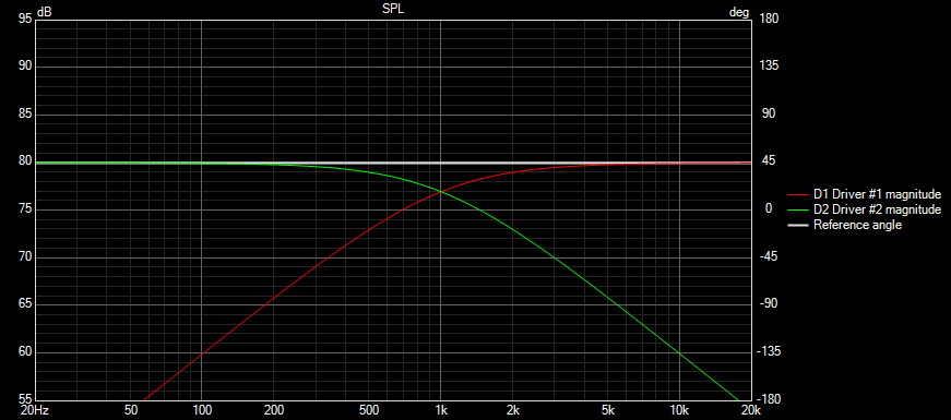
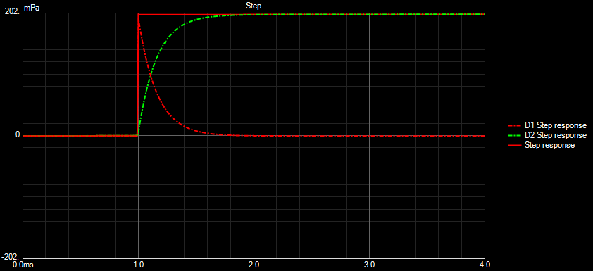
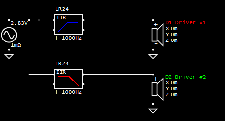
First order crossover is perfectly "time aligned", which can be easily observed using VituixCAD and "perfect" response, ie default driver.
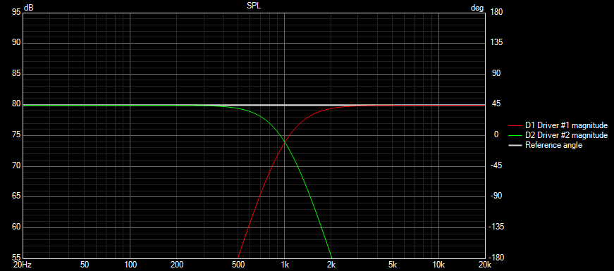
First order crossover at 1kHz, perfect flat response result:
Using impulse response view, step response of low pass, high pass, and total are show, looks as perfect as can be:
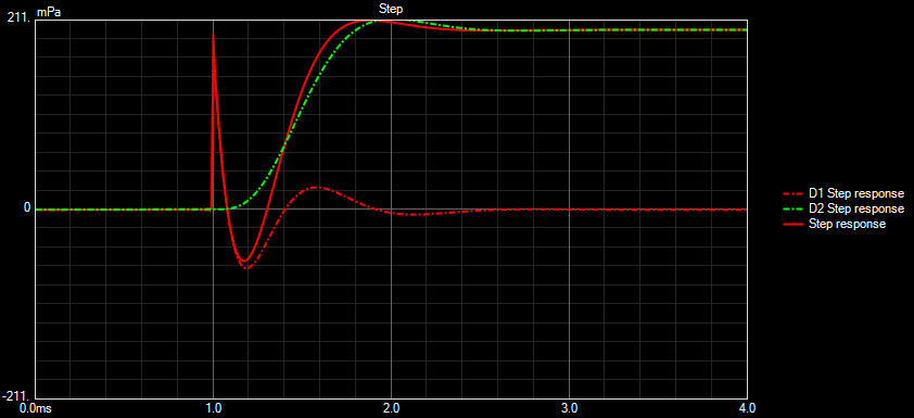
Change to more common 4th order LR:
Although total SPL is still perfect flat line, step response view is a bit less perfect:
Same interrogation can be completed for any speaker design. Hope this provides some useful information, unrelated to min phase topic whatsoever.")