The Formica will remain as of right now. It will have virtually the entire front in that Butterrum Granite pattern, and the upper half that same pattern in the back. The only black will be the rear inset PR mount, the terminal plate, the corner handle on the top rear edge, the drivers themselves, and maybe the corner casters if I can get them incorporated. The shape may not allow it. The casters and maybe the handles will not be present on them in 2 weeks. I won't be able to get those installed by then amidst everything else.
Was too cold Sun/Monday, so they are now cleaned up, poly'd, and almost dry. It is supposed to freeze again tonight too. I aim to have all but the baffles done by the weekend.
I'm using a set of dual terminal plates that I ordered from Europe with free shipping, Gersbach-Sound-Technik via their ebay store. A lot of items are branded as Dynavox but unaffiliated with the drivers, and they handle a lot of Intertechnik components too like Audyn Q4, Q6, Sn, and iT coils.
These are the ones I ordered. They are pretty strong plastic, terminals are good, and a circuit swap link is a nice touch too. https://www.ebay.com/itm/275298420526?hash=item401910872e:g:dMAAAOxyBotTafq6
Pending assembly for whoops tomorrow, all holes are cut and predrilled for screws. Sealing tape, gaskets, and damping also to be installed. Of course tweeters, woofers, PRs, handles, and terminals will be mounted after all of the above.
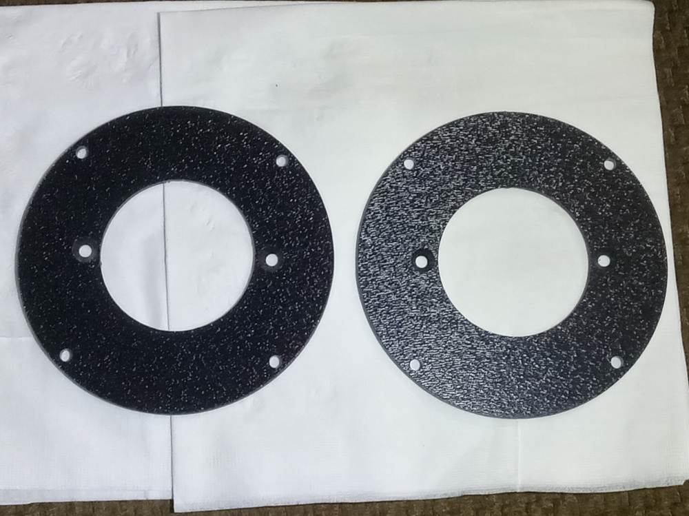
These will be used in 3 projects, so I cut the diameter of the next tweeter on the back side to make it easier. In retrospect, the rebate of the current tweeter is the same diameter as the future hole, so I didn't even have to do that.
I can lay the cabinets flat on their backs without setting it on the PR. I CAN make a grill or trim panel, but I have not even commenced or thought hard about that yet,
I also should add that the break in the offset panels makes a ridge of double thickness for really stiff reinforcement. It also varies the thickness of the panel so the possible flex is reduced. The additional fact that the particle board was warped before assembly, and is not now, means they are also under tension. This also helps.
Dense foam rubber, I got a roll from Mark a few years ago, and I used it here. I yelled into the box, and got no hollow sound or reverb. I then added a roll of Monacor Dammewolle laid across the back per cabinet and a handful of polyfill behind the woofers. After I wire up the cup to drivers, I can mount and measure. I should have them ready by Friday...
I had quite a few of them, and they were the only thing shy of having time to convert to bolts and inserts that would hold the baffles tight. It looked funny with those in the baffle and the torx Spax on the lower, so I changed them all. This has definitely been a build to "use what I have".
Okay, the event is over, so now I can give more info... these cabs will hopefully be used 3x for different projects, so the positions of drivers and using the burly PR was not an accident.
I called these the Opaz, after all of the Mercury Topaz in that Era missing the T on the badge. Here's why...
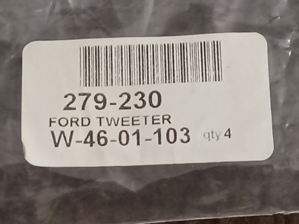
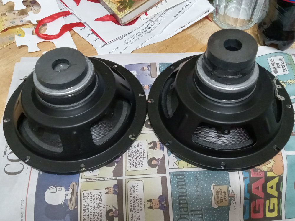
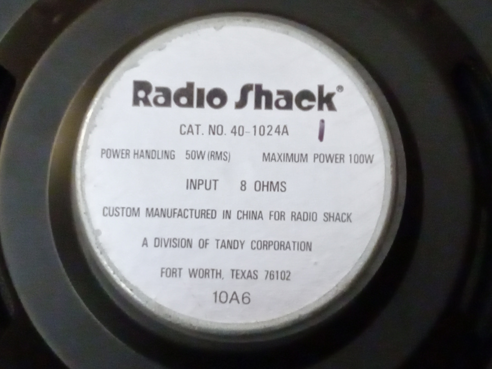
I used a Radio Shack 40-1024A 8" poly cone (bought each for $35 in 1997), and a Ford cone tweeter from the mid '90s used in the A pillars in something like the Taurus. The Fords were a buyout about 18 years ago from PE for between $3-5, IIRC. They came with 24uF caps, so I figured they would reach low enough.
The RS were off enough in spec from each other and high enough Q, that I had to do something about it. I had 4 magnets from a couple old microwaves I had saved. Using one donut on the lower Q driver and 3 on the other matched the Q at about 0.48, which is enough lower to get the job done. I just epoxied them on the backplate. Modeling went for anything from 22-25 ltrs, tuned to 36 Hz. I had a set of RSS265-PR on hand for the job.
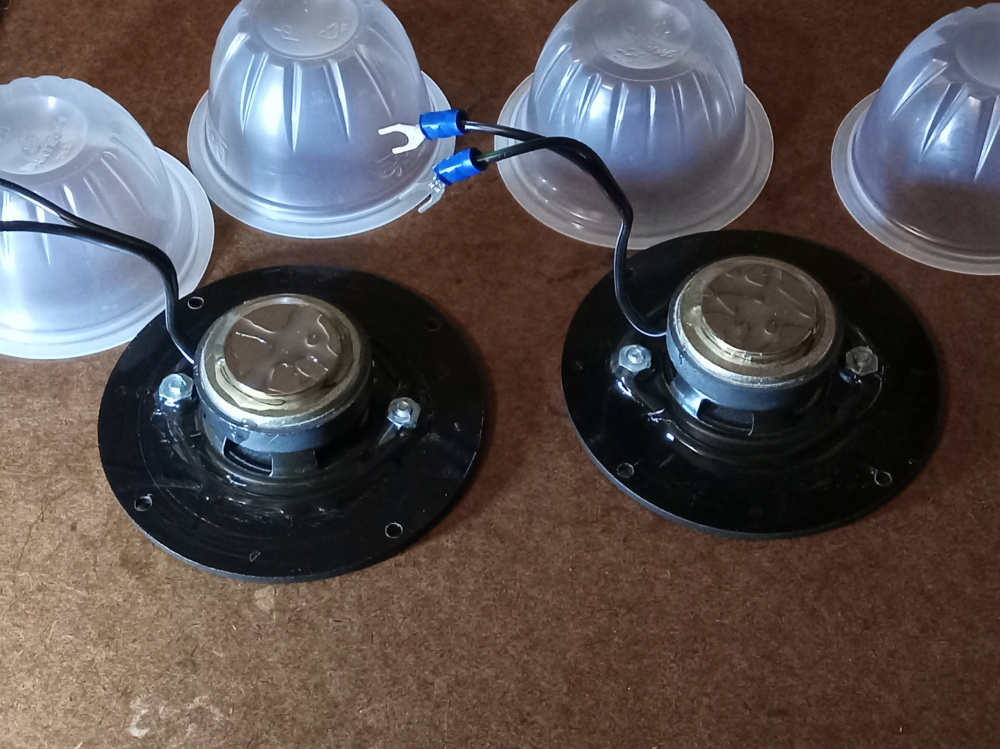
I had to chamber the tweeters, as they were for free air mounting. I used 2 Dole fruit cups per tweeter with adhesive between for rigidity as the chambers. I found Walmart.com had a set of 5x 4" diameter and 5/32" thick ABS discs for $8, and used them for the faces. I just located center like I learned in geometry with a compass and 4 arcs, bored my through hole and the mounting points. The frame was sealed to the faces with E6000. I also had a couple Neo slugs doing nothing, so I added them to their backplates. I did this to the woofers, so why not the tweeters? It didn't hurt for sure. Then the chambers had fit snugly with a ring of wool batting immediately behind the driver, and stuffed with shredded bamboo rayon fiber fill. Q of 1.6 and 1.7 with Fs of 500 and 600 roughly resulted as seen earlier in this thread. The HD was low, and they reached to 1kHz easily.
Measuring the drivers in cab revealed easy responses to deal with for the most part, and it appeared sensitivities were rather close initially.
More later...
Initial model was done in parallel mode, and came out 1st order for the most part. I did not like the larger copper count, so I tried the SXO. It came out to 7 parts, so I gave that a whirl. The sound was a little sharp, so I reduced the tweeter level by going from 0.5 to 1.0 resistor in series, and dropped the 20 ohm I had across them with a parallel 100 ohm to further reduce level for a 16 ohm net parallel resistor. Then the off axis and bloom associated with these kinds of designs hit. I could tell there was Still peaking going on, so I dropped the cap across the woofer from a 10uF to an 8.0uF. This was all of the voicing I did over the course of 3-4 hours.
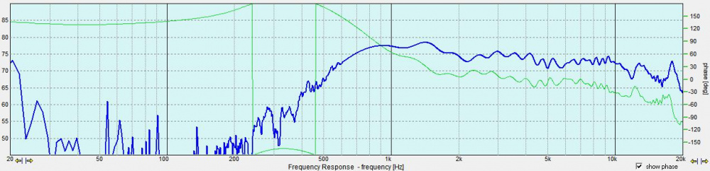
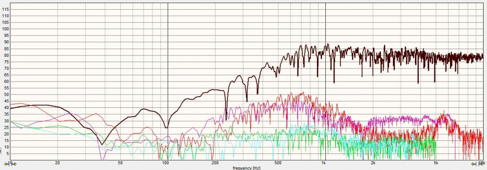
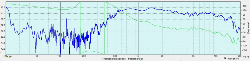
This is the result, applying the real values to the previous sim:
The reverse null sits at 2.5k, but the slopes approximate a spread LR2 with targets of 1.8k on the woofer and 2.2k on the tweeter. Being that the tweeter rolls off so gradually, this could place the actual xover point anywhere in this range, and LR2 is much less distinct at pinpointing the xover point with the reverse null in most cases. More often than not, the reverse becomes a trough instead of point as LR4 typically shows.
Power response is rather smooth rolling off without a dip, so this is good. Phase lines up rather nicely through the xover before diverging. The really glaring issue is the dip at about 800, and I find the mids lack the emphasis in this region.
I think Brad and Dirk both put the synopsis simply and accurately;
Brad- "I think you have built better, but you did the best you could with what you selected."
Dirk- "What's not to like? Not bad at all. A poly cone woofer and a cone tweeter that are not fatiguing."
I'll update the thread later with final system FR plots....
Cool idea to match Q by gluing old microwave magnets onto existing magnets. Any tips about the magnet orientation and how to keep the magnets in place as the epoxy sets? Do you just stick them on and let the expoxy set or do you have to clamp them in place to keep them from flying off?
The key is to set the right pole of the magnet atop the other. One way, it eliminates the field like if you were shielding it- and Q goes up! The other way, Q will go down by strengthening the field.
In terms of application, the correct position for lowering Q actually repels the additional magnet as you are applying it to the driver. Once it is pushed through the repulsion, it will again attract to the driver magnet.
You can apply the magnet from the side and slide it into place inside of the repulsion too as I've done on other drivers. I've found that sliding or placing the magnets without glue for measuring first helps with results. They will hold well via attraction for these purposes, but are much more permanent when glued. Labeling how they attract prior helps to make sure you place them right, and keep them separate when laid out to avoid damage or personal injury. Magnets can shatter on impact, or pinch appendages.
While prepping to glue the magnets, double check the positions or make sure they were marked for correct positions. It does not take much 1:1 5 minute epoxy mix to glue them up, in my case about a nickel size each of hardener and resin. I use a toothpick to mix for a half minute on scrap cardboard , and then lay it out on the mating surface of the additional magnet. Placing can be interesting, but just adjust by hand and hold for a minute while it starts to grab to keep it centered. I recommend wearing gloves to keep epoxy off of your hands, but they can get caught between the magnets. If using more than one added magnet, they tend to center themselves on the previous rather voluntarily if not approaching violently. The glue acts as a lubricant and the magnet just self centers.
Lastly, YMMV if this is even warranted or will be beneficial. If the driver has a large enough magnet already to saturate the gap, then there won't be much benefit in adding unless you want to raise the Q and add in an opposed magnet slug. This is more beneficial to the smaller magnet drivers with too high Q and under saturated gaps.
It isn't the first time I've done this...
I had a midrange that was under spec in sensitivity, and too high in Q. 5x holey Neo slugs brought it into spec.
Another couple notes-
1- Sometimes Neo is more applicable to achieve results preferred or wanted because of its stronger field.
2- This modification type can be steep in price VS initial driver cost. Some of these ceramic donuts are $20 from Amazon for example. A box of 10x of the Neo slugs also run about $20. Have an old nuker? I consider scavenging their magnets to be free.
I Picked up some doughnut magnets to play with. Tried on some cheapie woofers with a bit of cardstock between so I didn't damage the magnets sliding em on and off.
Started out .82 Qts. One magnet one way got .95, flipping it over got me .72, then doubling up the magnet got down to .66
Then I remeasured the woofer by itself and got .85.. hmm wonder if sliding magnets on and off might mess with the factory magnet.
To be honest, 0.03 on Qts is likely within % of measurement parameters, as it's really a small value. You can measure drivers successively one sweep after another and get measurements that differ by that much.
I experimented with adding magnets years ago, as well. Decided it was a lot of fun but ultimately did not pursue it any further.
For the record the driver was the 12" GRS poly cone. I managed to get Q down to the 0.6 range from the factory 0.9, which made it a nearly perfect acoustic suspension driver. I may revisit that project, the woofer is inexpensive enough, but I need another monkey coffin here like I need another hole or two in my dumb head.
This is awesome info Ben. PE has the 6.5" Buyout Poly that used to be $5 or so.. now about $8.00 or so. I'd like to make a nice 2 way acoustic suspension with this driver. I believe the Q is of this driver is .9. I'd like to get it down to .6
Well, finally put mic to these, and the tweeters were out of phase. LOL, Don't know how that happened, as I was careful. It happens to the best of us. Not bad measurement, and yes- they do sound better.
Comments
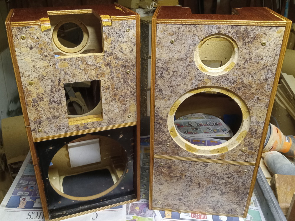
The Formica will remain as of right now. It will have virtually the entire front in that Butterrum Granite pattern, and the upper half that same pattern in the back. The only black will be the rear inset PR mount, the terminal plate, the corner handle on the top rear edge, the drivers themselves, and maybe the corner casters if I can get them incorporated. The shape may not allow it. The casters and maybe the handles will not be present on them in 2 weeks. I won't be able to get those installed by then amidst everything else.
InDIYana Event Website
Was too cold Sun/Monday, so they are now cleaned up, poly'd, and almost dry. It is supposed to freeze again tonight too. I aim to have all but the baffles done by the weekend.
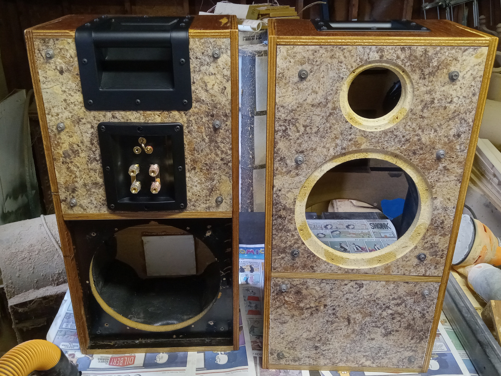
I'm using a set of dual terminal plates that I ordered from Europe with free shipping, Gersbach-Sound-Technik via their ebay store. A lot of items are branded as Dynavox but unaffiliated with the drivers, and they handle a lot of Intertechnik components too like Audyn Q4, Q6, Sn, and iT coils.
These are the ones I ordered. They are pretty strong plastic, terminals are good, and a circuit swap link is a nice touch too.
https://www.ebay.com/itm/275298420526?hash=item401910872e:g:dMAAAOxyBotTafq6
InDIYana Event Website
Pending assembly for whoops tomorrow, all holes are cut and predrilled for screws. Sealing tape, gaskets, and damping also to be installed. Of course tweeters, woofers, PRs, handles, and terminals will be mounted after all of the above.
InDIYana Event Website
What is that cutout behind the tweeter for? And why is that black panel for the PR inset? Are you making a grill to hide it?
These will be used in 3 projects, so I cut the diameter of the next tweeter on the back side to make it easier. In retrospect, the rebate of the current tweeter is the same diameter as the future hole, so I didn't even have to do that.
I can lay the cabinets flat on their backs without setting it on the PR. I CAN make a grill or trim panel, but I have not even commenced or thought hard about that yet,
InDIYana Event Website
I also should add that the break in the offset panels makes a ridge of double thickness for really stiff reinforcement. It also varies the thickness of the panel so the possible flex is reduced. The additional fact that the particle board was warped before assembly, and is not now, means they are also under tension. This also helps.
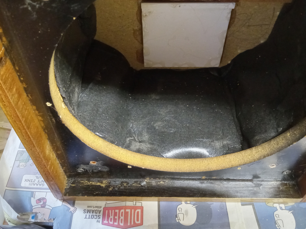
Dense foam rubber, I got a roll from Mark a few years ago, and I used it here. I yelled into the box, and got no hollow sound or reverb. I then added a roll of Monacor Dammewolle laid across the back per cabinet and a handful of polyfill behind the woofers. After I wire up the cup to drivers, I can mount and measure. I should have them ready by Friday...
InDIYana Event Website
InDIYana Event Website
Came out LR2 just below 2k. Parallel used more parts, and I was less happy with the model.
InDIYana Event Website
I just LOVE the metal roofing screws as baffle attachments!
I had quite a few of them, and they were the only thing shy of having time to convert to bolts and inserts that would hold the baffles tight. It looked funny with those in the baffle and the torx Spax on the lower, so I changed them all. This has definitely been a build to "use what I have".
InDIYana Event Website
Okay, the event is over, so now I can give more info... these cabs will hopefully be used 3x for different projects, so the positions of drivers and using the burly PR was not an accident.
I called these the Opaz, after all of the Mercury Topaz in that Era missing the T on the badge. Here's why...
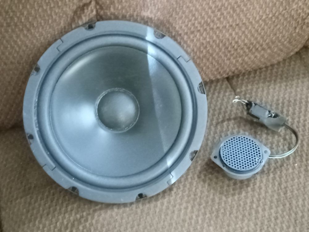
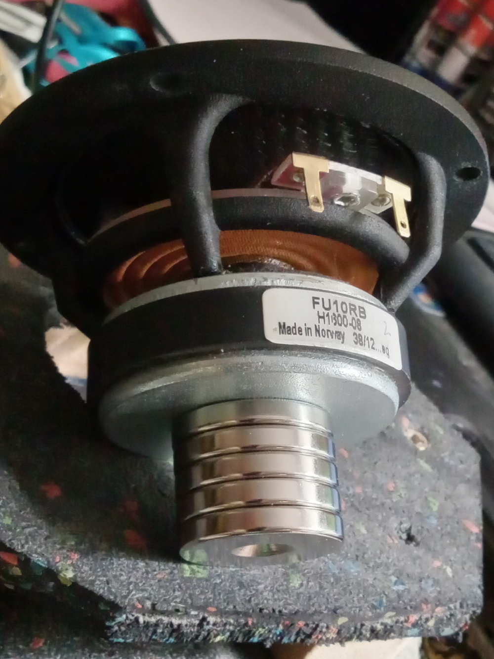
I used a Radio Shack 40-1024A 8" poly cone (bought each for $35 in 1997), and a Ford cone tweeter from the mid '90s used in the A pillars in something like the Taurus. The Fords were a buyout about 18 years ago from PE for between $3-5, IIRC. They came with 24uF caps, so I figured they would reach low enough.
The RS were off enough in spec from each other and high enough Q, that I had to do something about it. I had 4 magnets from a couple old microwaves I had saved. Using one donut on the lower Q driver and 3 on the other matched the Q at about 0.48, which is enough lower to get the job done. I just epoxied them on the backplate. Modeling went for anything from 22-25 ltrs, tuned to 36 Hz. I had a set of RSS265-PR on hand for the job.
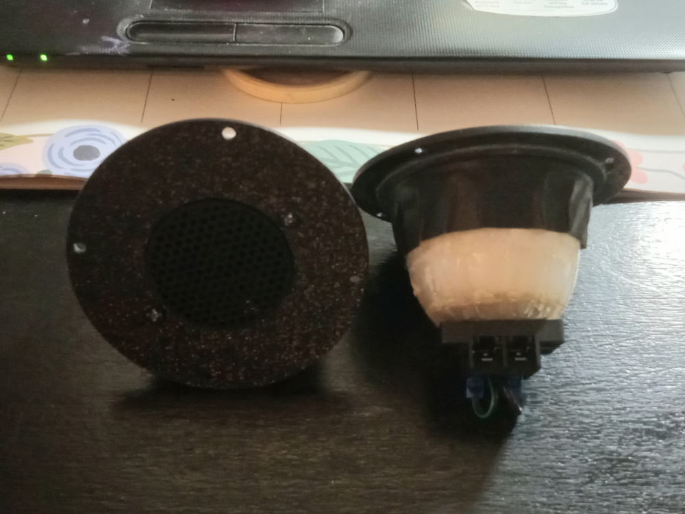
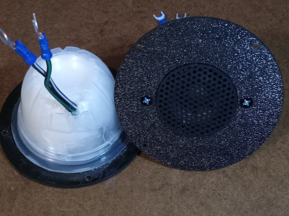
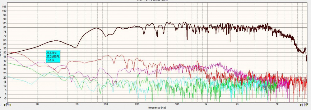
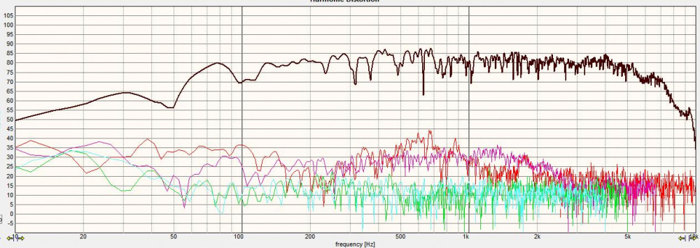
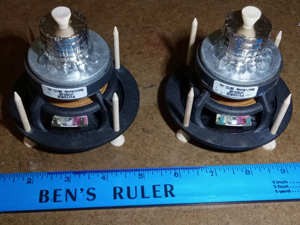
I had to chamber the tweeters, as they were for free air mounting. I used 2 Dole fruit cups per tweeter with adhesive between for rigidity as the chambers. I found Walmart.com had a set of 5x 4" diameter and 5/32" thick ABS discs for $8, and used them for the faces. I just located center like I learned in geometry with a compass and 4 arcs, bored my through hole and the mounting points. The frame was sealed to the faces with E6000. I also had a couple Neo slugs doing nothing, so I added them to their backplates. I did this to the woofers, so why not the tweeters? It didn't hurt for sure. Then the chambers had fit snugly with a ring of wool batting immediately behind the driver, and stuffed with shredded bamboo rayon fiber fill. Q of 1.6 and 1.7 with Fs of 500 and 600 roughly resulted as seen earlier in this thread. The HD was low, and they reached to 1kHz easily.
Measuring the drivers in cab revealed easy responses to deal with for the most part, and it appeared sensitivities were rather close initially.
More later...
InDIYana Event Website
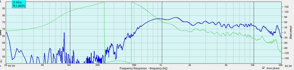
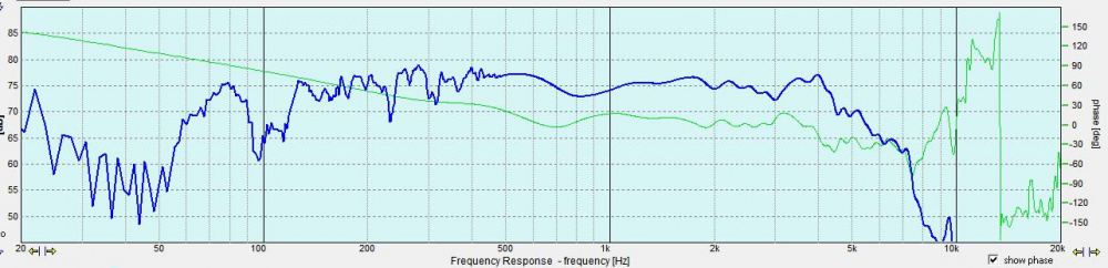
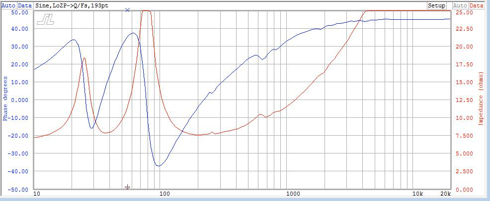
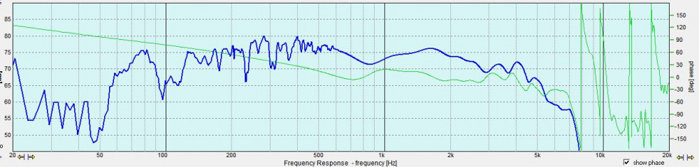
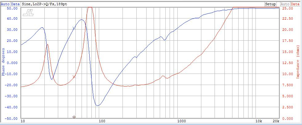
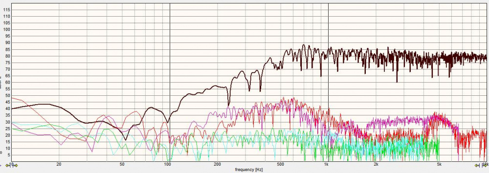
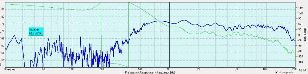
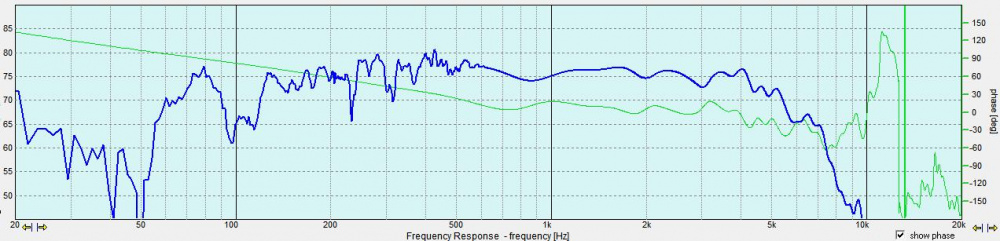
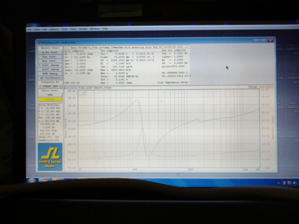
The FR plots and impedances came out as seen here:
Cab1, Tweeter1:
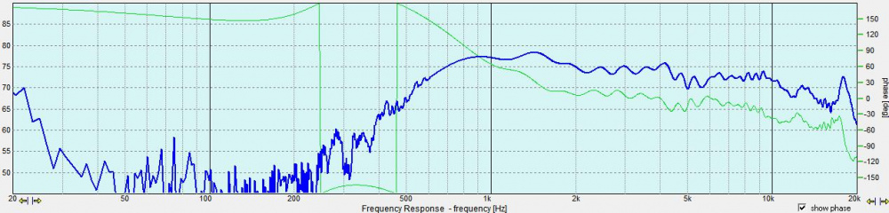
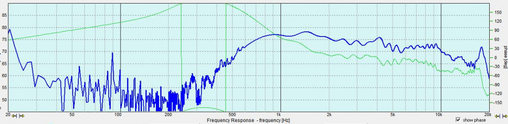
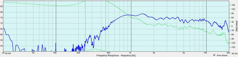
Cab1, Woofer1:
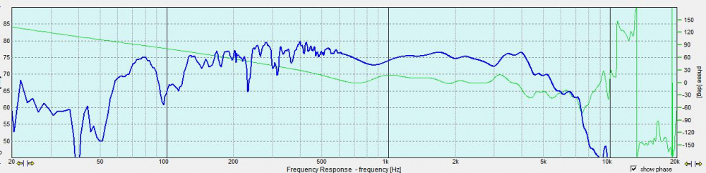
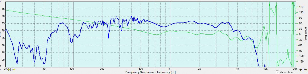
The other cab and drivers were measured for verification, but it turned out they weren't different enough to cause issues.
Cab2:
InDIYana Event Website
Darn, it looks like the order was mixed up of the previous plots. They are easy to decipher though and exist from 0 to 45 degrees.
InDIYana Event Website
Initial model was done in parallel mode, and came out 1st order for the most part. I did not like the larger copper count, so I tried the SXO. It came out to 7 parts, so I gave that a whirl. The sound was a little sharp, so I reduced the tweeter level by going from 0.5 to 1.0 resistor in series, and dropped the 20 ohm I had across them with a parallel 100 ohm to further reduce level for a 16 ohm net parallel resistor. Then the off axis and bloom associated with these kinds of designs hit. I could tell there was Still peaking going on, so I dropped the cap across the woofer from a 10uF to an 8.0uF. This was all of the voicing I did over the course of 3-4 hours.
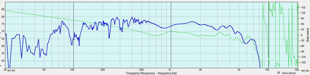
This is the result, applying the real values to the previous sim:
The reverse null sits at 2.5k, but the slopes approximate a spread LR2 with targets of 1.8k on the woofer and 2.2k on the tweeter. Being that the tweeter rolls off so gradually, this could place the actual xover point anywhere in this range, and LR2 is much less distinct at pinpointing the xover point with the reverse null in most cases. More often than not, the reverse becomes a trough instead of point as LR4 typically shows.
Power response is rather smooth rolling off without a dip, so this is good. Phase lines up rather nicely through the xover before diverging. The really glaring issue is the dip at about 800, and I find the mids lack the emphasis in this region.
I think Brad and Dirk both put the synopsis simply and accurately;
Brad- "I think you have built better, but you did the best you could with what you selected."
Dirk- "What's not to like? Not bad at all. A poly cone woofer and a cone tweeter that are not fatiguing."
I'll update the thread later with final system FR plots....
InDIYana Event Website
Cool idea to match Q by gluing old microwave magnets onto existing magnets. Any tips about the magnet orientation and how to keep the magnets in place as the epoxy sets? Do you just stick them on and let the expoxy set or do you have to clamp them in place to keep them from flying off?
The key is to set the right pole of the magnet atop the other. One way, it eliminates the field like if you were shielding it- and Q goes up! The other way, Q will go down by strengthening the field.
In terms of application, the correct position for lowering Q actually repels the additional magnet as you are applying it to the driver. Once it is pushed through the repulsion, it will again attract to the driver magnet.
You can apply the magnet from the side and slide it into place inside of the repulsion too as I've done on other drivers. I've found that sliding or placing the magnets without glue for measuring first helps with results. They will hold well via attraction for these purposes, but are much more permanent when glued. Labeling how they attract prior helps to make sure you place them right, and keep them separate when laid out to avoid damage or personal injury. Magnets can shatter on impact, or pinch appendages.
While prepping to glue the magnets, double check the positions or make sure they were marked for correct positions. It does not take much 1:1 5 minute epoxy mix to glue them up, in my case about a nickel size each of hardener and resin. I use a toothpick to mix for a half minute on scrap cardboard , and then lay it out on the mating surface of the additional magnet. Placing can be interesting, but just adjust by hand and hold for a minute while it starts to grab to keep it centered. I recommend wearing gloves to keep epoxy off of your hands, but they can get caught between the magnets. If using more than one added magnet, they tend to center themselves on the previous rather voluntarily if not approaching violently. The glue acts as a lubricant and the magnet just self centers.
Lastly, YMMV if this is even warranted or will be beneficial. If the driver has a large enough magnet already to saturate the gap, then there won't be much benefit in adding unless you want to raise the Q and add in an opposed magnet slug. This is more beneficial to the smaller magnet drivers with too high Q and under saturated gaps.
InDIYana Event Website
It isn't the first time I've done this...
I had a midrange that was under spec in sensitivity, and too high in Q. 5x holey Neo slugs brought it into spec.
Another couple notes-
1- Sometimes Neo is more applicable to achieve results preferred or wanted because of its stronger field.
2- This modification type can be steep in price VS initial driver cost. Some of these ceramic donuts are $20 from Amazon for example. A box of 10x of the Neo slugs also run about $20. Have an old nuker? I consider scavenging their magnets to be free.
InDIYana Event Website
Good stuff. Thanks for the info!")
I Picked up some doughnut magnets to play with. Tried on some cheapie woofers with a bit of cardstock between so I didn't damage the magnets sliding em on and off.
Started out .82 Qts. One magnet one way got .95, flipping it over got me .72, then doubling up the magnet got down to .66
Then I remeasured the woofer by itself and got .85.. hmm wonder if sliding magnets on and off might mess with the factory magnet.
To be honest, 0.03 on Qts is likely within % of measurement parameters, as it's really a small value. You can measure drivers successively one sweep after another and get measurements that differ by that much.
InDIYana Event Website
Yeah I suppose the first measurement could be a fluke. All the ones after that were in the .85 range
What Ben said.
I experimented with adding magnets years ago, as well. Decided it was a lot of fun but ultimately did not pursue it any further.
For the record the driver was the 12" GRS poly cone. I managed to get Q down to the 0.6 range from the factory 0.9, which made it a nearly perfect acoustic suspension driver. I may revisit that project, the woofer is inexpensive enough, but I need another monkey coffin here like I need another hole or two in my dumb head.
This is awesome info Ben. PE has the 6.5" Buyout Poly that used to be $5 or so.. now about $8.00 or so. I'd like to make a nice 2 way acoustic suspension with this driver. I believe the Q is of this driver is .9. I'd like to get it down to .6
That driver is a POS. The GRS poly 6.5" is lightyears better.
I would listen to JR about this, Vince....
InDIYana Event Website
JR has a mastered "playing in the dirt". His advice is always solid. Despite the price that GRS woofer is built like a tank.
Name for next JR cheap build: Mud Pies.
InDIYana Event Website
Well, finally put mic to these, and the tweeters were out of phase. LOL, Don't know how that happened, as I was careful. It happens to the best of us. Not bad measurement, and yes- they do sound better.
InDIYana Event Website
Glad you found it. I had similar "duh" moments with my Not Qualified speakers