Site Links
Howdy, Stranger!
It looks like you're new here. If you want to get involved, click one of these buttons!
Quick Links
Categories
In this Discussion
Who's Online (0)
Passive Resonance Suppression of drivers around Fs -VS- DSP - Discussion . . . .

(Originally posted by Wolf):
"It seems to be a relative misunderstanding amongst the active/DSP users with regards to Fs resonance suppression (or even upper end breakup) and the why and how it is applied and needed. I'm really trying hard to not sound insulting or that I'm belittling the active xover designer, as I know that in particularly Charlie knows what he is doing in that regard.
1. DSP cannot suppress an impedance resonance by applying output attenuation as it typically is used. You cannot short out or shunt off a parallel compensation using DSP. This is factual.
2. This issue with DSP/active is not about xover interaction and impedance. This is about Fs compensation, or the other end of shorting out an upper breakup. This is not involving the load VS frequency rolloff and interaction. Compensation is not always about rolloff.
3. This is ALL ABOUT the impedance of the driver and the effect of the driver's inherent resonances on the driver's response and not on the xover and how it affects the response. All resonances occur with some kind or form of energy storage and a corresponding impedance bump, no matter how small. You can attenuate to your heart's desire and try and kill the issue this way, but it does not always work by attenuation. That bump is still present, and rears it's ugly head in the response because of it. In some cases you have to short out the bump to minimize its footprint and not sound buzzy, nasal, or piercing. Just attenuating it does not prevent the driver from seeing the offensive signal and self resonating to where HD is higher in the response than necessary."
Charlielaub replied:
OK. Thanks for your thoughts Ben. I don't find what you are saying insulting, but thanks for allowing for that possibility. I see the point you are trying to make about a network in parallel with the driver and that this is not something that can be duplicated by manipulating the input power (e.g. with DSP or with a passive series network).
Personally I don't feel that the impedance peak resulting from the mechanical resonance of the drivers (meaning at Fs) is affecting the other parts of the passband. The energy storage is not broad band, it is by definition stored in the resonance at the resonance frequency. Other frequencies away from the peak are not coupled to it except through HD and IMD perhaps.
If you can explain in some detail about how the passive shunt is doing something special that I am not seeing, please do! I would love to learn about that. I have to admit that I am just off doing my DSP thing and because of that I do not really give passive crossovers much thought, so I may be missing some key point or what not.
Comments
Steve_Lee said:
How does one identify the need for a Fs resonance shunt, Wolf? (I'm trying to understand).
If one avoids passing signal containing frequencies at or near Fs to the driver (steep slopes) using DSP, does this not prevent the problem you identify?
Wolf replied:
Let's say that you don't pass the frequency that is offensive, but you really can't say that. Said frequency may be -50dB down from nominal, sound about right? That frequency still marginally will excite the driver because it is present, even at -50dB, because the output at resonance is easier to create. Upper harmonics will also still be there, and likely in-band and very audible. Remember that suppression minimum is -25dB, good is -40dB, and gone is -50dB. You can roll it off, but expect peaking HD to come through.
OK, I mostly understand the reply concerning residual signal/harmonics effecting the driver but my 1st question above still needs attention, please?
How does one identify the need for a Fs resonance shunt?
Then Wolf added to the conversation:
One more thing- you have to have a voltage divider upstream for a parallel/conjugate/shunt circuit to do anything more than affect the impedance passively. If you want the frequency response benefits, there has to also be a series component before such a circuit. Such a thing as a series cap is usually used to prevent turn on pops in tweeters running active, so in thus way it can serve a dual purpose.
battle of the bots:
Passive: pure shunt, but problematically less accurate target (ie broader, blunter hammer around fs) per components’ +/- % range?
Active: dead on (+/- 1 db, and name your Q) but limited (up to 2x -16dB) attenuation. How low do ya need to go?
Would be interesting to see actual freq chart result comps (not just modeled) of both approaches. Thinking both can be successful approaches.
Interesting thread - great info to get a better understanding. Thx. While I haven’t seen the issue/need in my passives (coax mid/ tw), maybe it’s biz I target high(er) crossover points.
Re: woofers, I find fs is not only audible but can be seen when running freq measurement sweeps.
Thanks for moving this thread. I'm glad we won't be cluttering up JR's thread.
This is a 3-way system I built using a MiniDSP 2x4 HD, 8" MCM woofer, HiVi dome midrange and Fountek ribbon which is similar to JR's system just with less expensive parts. I used a passive crossover between the mid and tweeter which contained no impedance compensation. Starting on page 26 of the attached PDF you will find individual driver responses with impedance curves, the EQ applied and the resulting system response. I set the woofer to mid/tweeter crossover at 1Khz 48 db/oct LR IIRC. The DSP handled the high pass on the mid/tweeter combo.
I think the resulting response measurement look good and the speakers sounded as good as they measure (as in really really good). Am I missing seeing the sins that can't be fixed with DSP or did I just get lucky with the drivers I used not needing passive compensation?
Ron
A lot of times I guess it's instinct, listening, measuring, or practice where I see that a notch as such is needed. I suppose the case in point examples should likely be the ring-radiator type tweeter and the average dome type midrange, as well as an acute spike in the breakup like that of the Seas W18 woofer. These are types that may benefit from such a circuit. I'll omit conical mids here, as chambers for them can be made to suppress such an Fs issue. Even some planar or ribbon tweeters benefit from a cavity resonance shunt if it's large enough in influence.
I am also going to comment on the using 8th order acoustic rolloffs from DSP, supposed brick-walled filters, or steeper slopes. I do not prefer these kinds of responses as I can hear one driver stop and the adjacent one start in some cases. The drivers do not sound like they are working together, nor do they seem blended well. The blended LR4 et al of typical alignments should therefore likely be adhered to for comparison's sake between active and passive.
I suppose 8th order (48dB/oct) filters may suppress far enough to be below that of the -50dB threshold, but I'm personally not accustomed to these slopes in practice for the previous reasons. I just don't feel these kinds of slopes are warranted in most designs if shallower will still yield great results. Using LR4 acoustic summations only suppress to -24dB/oct, and LR2 to -12dB/oct, for examples.
Another option is to use a series xover. DSP also cannot do these, and I'll tell you why they also can be beneficial for the same reasons. Parallel networks run on the methods of increasing impedance in the stop-band for series components, and shorting them out in parallel or shunt circuits. In a conventional series xover, the driver that is in the stop-band is pretty much shorted out in its entirety while the other plays for odd order electrical filters. You still have the series components in higher than 1st order electrical as well which increase impedance. So, the opposite methods are in place for the other topology.
The reason I bring up the differing filters, is that the XT25TG30 is a tweeter with no ferrofluid and a 25-30 ohm impedance at resonance. A lot of compression drivers can also relate to this kind of driver inherent behavior. If not suppressed sufficiently or using a high enough xover or slope, this will allow the tweeter to buzz nasally in the tenor voice range, as well as create a dip in the adjacent woofer's response. For this reason, the SXO can make the XT25 behave a little easier because of how they operate together.
I know Lars Risbo is of the mindset and has done studies that series resistance can reduce HD when implemented in parallel notches. I understand that applied damping can have merit in this way. On the other hand, I have done many filters with both the series and tank style notches in tandem to say that suppressing the resonance in general should have a positive result. If you reduce the output by damping it in either method, then HD should be reduced if the offender was a source of it. I'm all for using whichever method works more efficiently,effectively, and easier with fewer parts.
The other driver(s) I want to highlight now are in particular the TB flat aluminum cone woofers and midranges. In measurement of 3-4 of them in the available sizes at one time around 2011, they all had a self-resonance due to the energy storage created by the flat diaphragm itself. The smaller the cone, the higher was the frequency. I tried 3-4 different parallel notches targeting this cone mode without success of suppression. The parallel notch was ineffective at this problem. However, a series notch across it was able to nuke it relatively easily. I still feel this is one of my best designs and listen to them often.
There are many examples I could provide such as these above from my past endeavors. I'm sure JR, Scott, Craig, and others have relatable stories too.
InDIYana Event Website
You make some good points Ben of what your ears have been telling you for years.
It's very enlightening to see why high order filters of DSP are not a cure-all, as purported by some DSP-only fanatics.
Here's an example:
acoustic LR4 at the mid-tweeter crossover point:
acoustic LR2 at the mid-tweeter crossover point:
What? They look virtually the same, I hear you say?
But why does the acoustic LR2 sound better?
I assure you there's no smoothing or tricky business here. Both graphs look super smooth because I used the most well behaved drivers for the job.
The reason for the better sound is revealed in a 360 degree measurements, which is then stitched together for the power response and (related) predicted in room response of the acoustic LR4:
Now look at acoustic LR2:
It's just 2-3dB at around that upper mid / lower treble band. But remember 2-3 dB is the difference in double the power eg. 10W vs 20W, or 100W vs 200W watts. And that 4KHz region... ooh you do not want more of that. Next time to hear a toddler having a tantrum, pull out your phone and do an FFT (I did, but I'm a super nerd)... it's all in the 4KHz region. Ouch!
My point is, this is the reason why acoustic LR2 is just right, if one is able to do a design with it. Unfortunately, not all drivers can do this. You need a drivers that can extend well beyond your intended passband for at least an octave. Drivers whose response fall off a cliff can't do this.
About 2 decades ago, Greg Givler presented a 2-way 5" + ribbon based speaker that was well received. This kind of surprised John Krutke, because from what I recall, he wasn't a big fan of ribbons. Higher distortion, unable to tolerate low crossover points etc. And it used a midwoofer which had a really boring harmonic distortion profile- the GR Research M130. Zaph was a big fan of harmonic distortion testing, and I think he was somewhat surprised that it was nice sounding speaker.
He wrote a piece about it here:
http://www.zaphaudio.com/Givler1.html
It's taken me awhile to see what the magic is all about with acoustic LR2... but I can now measure and SEE that a bit part of it is in the power response and predicted in room response. Zaph suggested that it could the power response (amongst other reasons)
As for Brickwall linear phase?
Looks quite good doesn't it??
Why does it sound so... err... wrong? Or so bad?!
Our dear humble Ben. That's like a euphemism right?
Let's have a looksy... see what he's talking about.
I say - What the F A R Q !
Conclusion- Can you do some things with active that you can't do with passive? YES!
Can you do some things with passive that you can't do with active? YES!
DSP is a tool. Don't think it's a cure band-aid for a bad design.
Based upon all of this I think the real answer lies in a hybrid approach to sound shaping of speaker drivers using both passive and active methodologies where the net result is as near perfect as possible.
I too am coming to the conclusion that a MT passively XO'd and EQ'd by DSP while the W~MT XO handled by DSP may just be a superior approach.
This thread is GOOD discussion!
Ben brought up two different scenarios: one about driver impedance compensation at Fs and the other about taming peaks, e.g. breakup or other.
I reached out to Lars Risbo and asked him about his tech note that is published on the Purifi web page here:
https://purifi-audio.com/wp-content/uploads/2022/03/220211_R05-Notchfilter.pdf
Lars told me that, yes, a passive SERIES element (not parallel notches) is best at removing the FR peak AND reducing the distortion signature from it that occurs at lower frequencies. That is something new to me for sure, and not something that DSP can do although I would like to make a comparison of equivalent FR notching between passive and DSP to see the extent of the different.
The bulk of what Wolf wrote about seemed to center around impedance compensation. That is something totally different than what Lars is doing (he is filtering). Also, the impedance itself does not represent any sort of energy storage, or there would be a peak in the FR as well at Fs. The amount of energy storage is described by the Q of the resonance, and at Fs this means Qts, and that is not typically very high. My take of Wolf' post was that this issue is all about removing the negative influence of the impedance peak on the (passive) crossover network function. THAT is a non-issue when using a DSP system, because the driver impedance doesn't matter. It is only a problem for the passive network that uses the impedance ratio of two branches as a function of frequency to make a voltage divider and pass or block power that is delivered to the driver. If the attenuation is falling off because there is no impedance compensation at Fs then yes you will probably have the driver making some undesirable sounds because (A) the excursion will be higher near Fs compared to higher in frequency and (B) distortion is always higher near Fs for a driver (based on my observations). Undesirable power that reaches the driver at FS will cause excessive motion and distortion products that occur at higher frequencies. But to reiterate, this is a non-issue for DSP.
The other thing I want to comment on is tktran's post. I didn't quite see the tie in to the thread topic. It seemed to be more a comment on what is the most appropriate filter type and order to use. That would apply equally to passive or DSP filtering alike. You can implement LR2 or LR4 both passively and actively with success, or not, depending on the particular system you are working with. The same goes for whatever very high order filter type is brought up: the designer must choose wisely. I get the idea that some here think that DSP means "high order" or what not. DSP is just a vehicle to implement active filters that benefits from being very flexible and powerful and the filters can be implemented exactly (e.g. no component tolerances are mucking around with the response, which can also happen with analog active filters). There are certainly users who don't have any idea what they are doing but use DSP or analog pro audio crossover boxes to implement some sort of crossover with whatever drivers they decided to put into some cabinet and then they "tune by ear". That is not good speaker building. But I could say the same thing about people who buy a pre-built off the shelf passive crossover and combine that with some random parts. Also bad. DSP just makes it easier to do and I guess some people like to fiddle and twiddle settings and so on, without really knowing what is happening.
You have to realize that a series notch is in parallel with driver and parallel notch is in series with driver. This is critical for understanding. Lars states that a series resistance with driver as in a parallel notch will attenuate and damp the signal to reduce HD. He does not believe that a shunt or series notch is able to reduce HD, but I tend to disagree with these findings.
Energy storage does not always represent as a peak in response, but can be a cancellation that shows as a dip in response. Even when seen as a dip in response, the CSD or waterfall will show a ridge under a measured timeframe. Such as the surround resonance of a lot of 7" drivers have a dip at 1.5k. At these points, there are bumps in the impedance that show it is there.
This is not about removing the influence on the transfer function of the xover. I understand what you are referring to as the reduction of effectiveness of the xover due to the resonance not being compensated. This is not the only problem here, even if they go hand in hand passively. The resonance is still there, even when a DSP is in place, so it is still a problem. I do not understand why you think it is not. There were some of the same kind of responses in the PETT thread with bcodemz as you are describing here. I know that DSP does not apply to impedance; 1 because it cannot, and 2 because in most cases it does not need to in application. I am still of the opinion that compensation of resonances passively, whether series or parallel circuits, will cut down on the HD of the excited resonances.
I did not say that DSP means higher order, but the fact that using more common 2 or 4 orders is better for comparison's sake.
InDIYana Event Website
I do not consider the mechanical "resonance" of a driver at Fs to constitute energy storage in so much is that it is storing only enough energy to support the end of the passband so that it does not droop. OTOH the example you gave of the surround moving in ante-phase is an example of a resonance I suppose. What Lars Risbo describes is something completely different than the Fs resonance. His notch networks (what every you call them") ) are creating a high impedance at the cone breakup resonance frequency but their primary function is to knock down the resonance peak in the frequency domain, not reduce impedance, in fact the opposite. He explains that increasing the impedance where the peak is located helps to damp the distortion, a current generated by the modulation of the voice coil inductance. But I don't forsee that technique to be broadly applicable to any resonance, like the one from the surround you mentioned, since the motor is not at all involved in that.
) are creating a high impedance at the cone breakup resonance frequency but their primary function is to knock down the resonance peak in the frequency domain, not reduce impedance, in fact the opposite. He explains that increasing the impedance where the peak is located helps to damp the distortion, a current generated by the modulation of the voice coil inductance. But I don't forsee that technique to be broadly applicable to any resonance, like the one from the surround you mentioned, since the motor is not at all involved in that.
Also, when I bought up DSP and "high order" it was more of a general comment and not aimed at anyone in particular. The same goes for me saying "certainly users who don't have any idea what they are doing but use DSP" - that is not to call out anyone in particular on the low down! It's just my perception and occasional observation of a noob speaker builder who buys a DCX2496 and some drivers, puts them in a cabinet, and then without any sort of knowledge and without measuring anything dials away to come up with some crossover for their project. Hey I did this myself some 30 years ago when I was first getting into the hobby. I was clueless and I attempted an OB system as my first ever project. It was a birch ply large baffle that I just leaned against the wall. I was so confused at the time as to why it just didn't sound right!
Finally clicked in my head...
So I'm to assume the "shorting" that occurs with a series LCR (in parallel with the driver) creates a braking effect to try and squash the excessive mechanical movement at the tuned frequency of the circuit. Similar to how standard brushed DC motors can be effectively braked by shorting out the terminals. Since they are both motors with the terminals electrically linked to moving coils.. just linear vs axial.
Kinda sorta similar to how copper or aluminum on the pole piece will create a repulsive feedback force due to Lentz's Law to put the brakes on mechanical movement that does not correlate with the magnetic field (distortion).
All stuff just reducing applied power can't help much with. Reducing the throttle vs applying the brakes so to speak.
Just thinking out loud. I'll let the smart people talk now")
My context of my tie in was that I wanted to show our other readers evidence of one of the things that has been observed by Wolf, through listening, for many years- that the use of DSP (by some users) to tune filters with higher order slopes. These DSP users then declare that is one of the reason DSP is superior- because it is quick and cheaper to do with DSP than analog parts eg LR8, or possible to do with DSP but impossible to do with passive eg.brickwall linear phase.
But they are not audibly superior. They are inferior.
Sometimes visuals helps explain for are the readers who are following this thread.
As an aside, and again for the benefit of readers following along, I wish Lars’ documented method had not been complicated by the nomenclature of the filter. What he calls a series notch (made of the 2-3 components wired up series) is what passive circuit designers usually call a parallel notch filter, because this is where they are in relation to the driver they are acting on.
However, that method is not anything new in the sun- it was used and has been championed by JonMarsh @HTguide for many many years. Decades. Unfortunately JonMarsh never got around to documenting it thoroughly, nor did he show evidence through images that it indeed suppressed harmonic distortion. Very recently, and after Lars’ published document, he went back and documented this.
The unfortunate side effect of this was that for decades, there were debates/discussions between those who said that it helps eg. JonMarsh, Dennis Murphy, who used the SEAS Excel drivers as high as they wanted, and used notch filters, and those who says it didn’t help. eg. John Krutke or the late Sigfried Linkwitz, these two latter gentleman both insisting that to avoid the HD3 harmonic distortion peak, these driver drivers need to be crossed over before 1/3 of the resonant peak.
We now know this to be not true, but ONLY if one employs a notch filter by passive components.
This cannot be done by active filters.
I thank for taking time to document this.
I haven’t commented specifically about Wolf’s comment on the 1) impedance peak compensation around F(s), or 2) at the cone edge resonance (around 500Hz-2KHz) or 3) anywhere else there may be a small blip in the impedance. This is true that they can only be done with passive components. DSP can’t do that.
Whether they need to be done to a benefit, well I try to keep an open mind. And always willing to learn something new (or learn something to refute or affirm my previously held beliefs)
Consider a midwoofer like this unit:
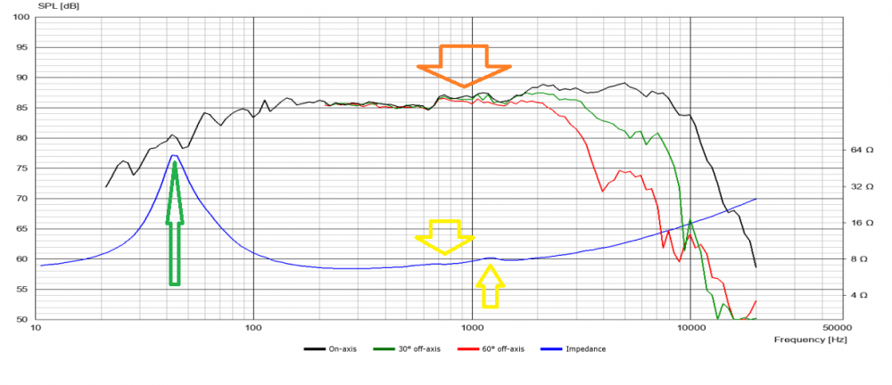
When using active OR passive crossovers, I correct for the orange. I ignore the yellow.
I'm not sure I understand what Wolf is saying.
Are you saying that correcting for the yellow, via passive components, helps the orange?
I don't correct for the green, whether I'm using an active (it can't be done) or passive filter (I thought correcting the orange is all that's needed)
What about a tweeter, like this:
I don't, but only because I assume that the tweeter is sufficiently down in SPL there, by about 30dB.
Do you correct for the green?
If so, do you have any evidence that you can provide us, that it helps? Don't forget that anecdotal evidence ("it sounds better") is a form of evidence. I don't mind that at all.
Finally, here are 2 soft cone midranges:
Are there advantages of correcting for these blips (in yellow)
I'm not trying to challenge anybody. I'm just trying to understand different methods of crossover design. I hope this post helps Steve also.
I'm right there with you on these questions and the examples provided make things crystal clear - thanks!
Charlie, I was not saying the Fs was energy storage. However prominent it may be. The other examples were though.
Drew, Iove your analogy there, and you really do understand what I am talking about.
Thanh, sometimes by helping the orange, you fix the yellow in the process. It depends on how you fix it. Is it needed? Sometimes, but not always. Shunt components will do both, whereas series components won't also fix the yellow, but might not need to. Fixing green on woofers is not typically done, however, comping it can improve transfer function if the lowpass makes a bump there. This purpose has nothing to do with HD reduction however, even though it may serve that purpose. I've never done that myself for that reason. The green in a tweeter or mid response can be comped for better HD, and rolloff, audibly. The flock of yellow arrows; without knowing what is going on is hard to say.
InDIYana Event Website
Wolf - can you explain further "Comping" the green stuff in both woofers/mids & tweeters as you feel inspired, please?
No rush.
Thanks!
I am pretty sure I ready said why...
InDIYana Event Website
OK - I'll review again and see if I understand it. Thanks.
I guess I just don't fully understand the passive side of it sufficiently well since I am stuck in the active side of this hobby for now.
Comping is short for compensation, aka impedance compensation circuit.
Using passive parts (inductor, capacitor and/or resistors) to compensate for bumps or lumps in the the impedance; thus flattening it out.
Please correct me if I’m off target
https://www.diyaudioandvideo.com/Calculator/SeriesNotchFilter/Help/
https://www.diyaudioandvideo.com/Calculator/SeriesNotchFilter/
The first link shows basic schematic. I'm a little suspect of some of the info farther down that page.. as I thought the series notch would create an impedance dip to oppose the impedance peak of the driver. Perhaps they confused the parallel notch with the series notch?
Technically that calculator is designed for the Fs peak and not another peak. Can use it to help get in the ballpark, then load the frd/zma files for the driver measurements in your XO design software of choice. Plug the calculated values in there and tweak the values until it better matches the Fs peak. A series notch will be in parallel to the rest of the circuit so look for that in the XO software.
Essentially the circuit creates an impedance hole for the peak to fill.. If the hole is designed exactly right for the peak then the result is perfectly flat. Though reality loves to screw with perfection so you do your best. Fs can shift from driver to driver due to manufacturing variances so technically the circuit would need to change too if we are splitting hairs.
However, it will affect anything else in parallel in the circuit... Unless you put something to block in series before it in the circuit (to the left in typical schematics). For a tweeter the passive crossover should suffice for this. If active instead of passive, from what I've read, a large value capacitor would work without really affecting your highpass slope. As I understand it, that should help block the impedance dip from getting to the amp.
Drew - Thanks for the effort/patience in offering your explanation ^.
Take a look at how JB defines notches in PCD 8.0. There's definitely room for confusion.
The yellow arrows is not normally seen in an impedance sweep, if the Y scale is in the range of 100+ ohms.
When I zoom into and adjust the Y scale max to 20, 10, or 7 ohms; they are increasingly visible. They represent areas of interference, they usually represent a a peak or a dip in the frequency response.
This is typical for soft cone drivers eg. Paper or fibre cones, with multiple (albeit) small resonances or dip. Is it a local maximum (peak) or a local minimum (dip), depends on the mechanism. For cone edge resonances it’s usually a dip. But between 500Hz and 2000Hz; which spans 1500Hz but is actually 2 octaves musically, it’s can be challenging to see anything in the frequency response if it’s a narrow dip/peak. For 1/12 octave accuracy; we need 24 data points in 1500Hz; which means we need a resolution of 62.5Hz.
If you’re measurement indoors with a 5ms window you might miss small resonances. It’s often hard to see anything because if the window length is 10ms; then your frequency response resolution is only 100Hz.
One really needs a resolution of 62.5Hz or lower to pick up some smaller resonance. But that needs an impossible long window like 16ms. I’m talking measuring at 11 ft from the ground and any other reflective surface. One can get around this by using a Klippel Near Field Scanner, but that’s a $100K propositon.
So my question is; what do you do with those small lumps and bumps in passive crossover? I think you just have to accept them.
What you are referring to usually do go unnoticed, and don't need to be tamed. It's the ones that are visible in typical y axis scaling that raise flags with corresponding blemishes that even remotely get a second glance. Not that all of them even need remedied.
InDIYana Event Website
. . . or find a flatter driver . . .
I heard someone say something about a free lunch one time...
Playing around with several different drivers tonight using DATS V3 - This is pointless if using DSP exclusively for XO's.
It doesn't matter concerning Z that I can tell.
The only things that seem to matter to my mind are FR and Distortion as measured by a calibrated microphone.
This board is primarily geared toward passive XO designers.
This is why I think we keep talking past/over one-another concerning the different approaches (DSP -VS - Passive).
Can we/someone/administrator create a new sub forum here in the pull-down menus that allows us to post in either a passive or active discussion?
If there is no interest here [concerning Active/DSP], can I get a pointer to a dedicated active DSP XO discussion board?
Been measuring and exercising these 5" Bowers and Wilkins LF27170 mids with Fs and lower frequencies and they have dropped from Fs 300 Hz to 295 Hz after 30 min of play time so they need to be XO'd around 550+ Hz so far but I will be doing it actively - not with passive components.
Just trying to clear the the air/discussions while not discounting any given feedback.
I still need/want to do passive XO's for MT but stay active for the MT EQ and use active DSP XO for the W~MT stuff . . .
Thanks for tolerating me.
Edge diffraction can make a flat tweeter lumpy. It's fun to compare near field and far field measurements to see the effect.
Don't for get to take a measurement off axis, e.g. at least at 20 and 40 or 30 and 46 degrees, to see what is happening out there. Some HF drivers will have some peaking or dips on vs off axis and it is good to know about them.
That is my preference / set-up as well, and as such I'm seeing / garnering a lot with these discussions- thx