Update: I'm now up to test #17. Lots of frd's and zma's on file so far. On test #5, however, I blew the output chip on my DATS V2! Now it no long goes "whooooop" when I click the button. What happened is that, for each test, I connect the speaker leads to my amp and take NF mic measurements on the two ports. Then I disconnect the speaker from the amp, connect it to the DATS V2 leads, and run an impedance curve. On test 5, I accidently connected the DATS V2 to the power amp leads instead of the woofer leads by mistake. POW! My KLH power amp has about 32mV of DC offset at the output and that small amount of voltage instantly burned the DATS V2 output stage. I have a new IC chip on order from Mouser and when that comes in, I'll replace the burned out chip and see if I can get my DATS V2 to go "whooooop" once again! In the meantime, I'm using my WT3, which still works, but sometimes gives me garbage screens. I could also use my Arta jig to run impedance curves, but I have decided not to do so because I do not want to change my Steinberg UR22 gain settings between NF test measurements.
Man oh man, I have burned up so many dacs and mp3 players during speaker testing. Good luck on the replacement chip! Looking forward to the TL information dump!
But Chahly - Stahkist don't want speakers that look good, Stahkist wants speakers that sound good!
In case anyone wishes to play along, here is a zipped up file of my first 31 test measurements, covering all woofer offset positions available. The "read me" file gives you everything you need to know to set up a model and run comparisons. I'm using the Leonard Audio TL program, but Hornresp might also be able to model this as a 6th order bandpass alignment. Any questions, feel free to ask.
@Tom_S said:
Did you get your Dats fixed? What are they using for the output device?
Yup. All fixed up and working like new again. Probably blew the output transistors in the small SMT power amplifier chip when I accidently connected the leads to my power amplifier. My guess is that both DATS V2 leads must remain floating with respect to ground potential and when I accidentally connected it to my power amplifier outputs, for just a few seconds, this caused excess current to flow through the laptops 5VDC power supply ground connection.
Mouser sells this chip (Texas Instruments TPA6111A2) in two different size packages: SOIC (8) and MSOP (8). Both versions are 150mW Stereo Audio Power Amplifier chips. The SOIC (8) package has a 4.9 x 3.9mm body with 1.27mm ctr-to-ctr pin spacing. The MSOP (8) package has a much smaller 3 x 3mm body with a 0.65mm ctr-to-ctr pin spacing. Only the larger SOIC (8) package will fit the DATS V2 pad spacing. They are less than a buck each. Only 21,110 left in stock! I picked up 10 to get the quantity discount, so now I am ready in the event I make this dumb mistake again.
It has been slow going on this project so far. I've been going over the data and have been having trouble getting a good match between model and actual measurements. The completely unstuffed models tend to look "similar" to the completely unstuffed actuals, but when I compare the stuffed LA-TL models verses the actual stuffed measurements, the match ups do not seem very good at all. And I have been unable to develop a stuffing "fudge factor" to account for the differences. I will continue testing to see what I can come up with. Have only tested standard poly-fil so far, but maybe other types will react differently.
It has been slow going on this project so far. I've been going over the data and have been having trouble getting a good match between model and actual measurements. The completely unstuffed models tend to look "similar" to the completely unstuffed actuals, but when I compare the stuffed LA-TL models verses the actual stuffed measurements, the match ups do not seem very good at all. And I have been unable to develop a stuffing "fudge factor" to account for the differences. I will continue testing to see what I can come up with. Have only tested standard poly-fil so far, but maybe other types will react differently.
IIRC, your TM had multiple cavities and a tunable woofer position.
It's very good that unstuffed models are similar to the unstuffed measurements.
You might try stuffing just a portion of the line(s) and see what happens.
This is how we have fun!
But Chahly - Stahkist don't want speakers that look good, Stahkist wants speakers that sound good!
@Tom_S said:
Glad to hear you got it fixed! You must have used the fine tip on the iron for something that small.
I have the Weller 1010 station and used their fine conical tip. And even then, I had trouble keeping the pads from shorting together. Used .032 60/40 rosin-core and "pre-liquified" the pads with MG chemicals 835 liquid rosin flux. Was a little "blobby" looking, but no shorts. The best way to do this type of small work is with a hot air re-work station, but I don't have one. You probably missed this, but here is a link to the other thread with a couple pictures of what the final result looked like:
It has been slow going on this project so far. I've been going over the data and have been having trouble getting a good match between model and actual measurements. The completely unstuffed models tend to look "similar" to the completely unstuffed actuals, but when I compare the stuffed LA-TL models verses the actual stuffed measurements, the match ups do not seem very good at all. And I have been unable to develop a stuffing "fudge factor" to account for the differences. I will continue testing to see what I can come up with. Have only tested standard poly-fil so far, but maybe other types will react differently.
IIRC, your TM had multiple cavities and a tunable woofer position.
It's very good that unstuffed models are similar to the unstuffed measurements.
You might try stuffing just a portion of the line(s) and see what happens.
This is how we have fun!
I will give this a try and see what happens. Maybe I am jamming too much stuffing in the line. Maybe try putting just a little bit in at a time and then watch how the peaks and dips move around.
Progress report: I'm now up to test #42. Based on my analysis so far, I have pretty much come to the conclusion that a woofer offset distance of about 2 to 3 inches for FS1 produces the best looking unstuffed bandpass graphs. So I fixed the woofer at the 2.5" FS1 offset position and generated a few modelled verses actual measured FR comparison graphs. The variable is the amount of stuffing, ranging from no stuffing at all to a low of 0.2 lbs/cu.ft in some of the rear sections to a high of 1.2 lb/cu.ft. in some of the front sections. The average stuffing density in the charts below was approximately 0.2 lbs/cu.ft of poly fill for test "FR32" and 0.4 lbs/cu.ft of poly fill for test "FR34". Test "FR33" had no stuffing at all. The attached spreadsheet shows the detailed poly-fil stuffing density by line section:
First up, here is the completely unstuffed FR33 model verses actual frequency response. Looks like a fairly good agreement without stuffing, a little off on some of the peaks, but not too bad. Ignore the fact that this is not a very good bandpass at this point. My first goal is to match model to actual and then work on improving the shape of the bandpass:
Lightly stuffed (FR32, 0.2lbs/cu.ft poly-fil) model verses actual frequency response. There does not appear to be a good agreement from 50 to 200Hz between modelled and actual with light stuffing:
Moderately stuffed (FR34, 0.4lbs/cu.ft poly-fil) model verses actual frequency response. Again, poor agreement, this time at both higher and lower tuning frequencies:
Here are the LA-TL computer models comparing unstuffed (FR33), lightly stuffed (FR32, 0.2lb/f3 avg), and moderately stuffed (FR34, 0.4 lbs/cu.ft avg) transmission lines:
Here are the actual measurements comparing unstuffed (FR33), lightly stuffed (FR32, 0.2lb/f3 avg), and moderately stuffed (FR34, 0.4 lbs/cu.ft avg) transmission lines:
Finally, here is a comparison of the moderately stuffed actual (FR34) verses the lightly stuffed model (FR32). I did this comparison to see if an approximate 2X stuffing fudge factor would help the agreement. But it does not look much better.
Going forward, I will be repeating the comparisons above, but this time switching to the same lbs/cu.ft of Utratouch denim. I also did some testing using a SPA250 plate amplifier at various xover settings, to see how a plate amplifier could be used in combination with this bandpass alignment. Will show how that worked out in a future post.
Wow, you are really in deep! I suspect that LA-TL modeled unstuffed vs various stuffing graph is not that accurate. All the hornresp modeling I have done as well as measured show less bass response around Fs for moderate to heavy stuffing.
And about stuffing, I have never reconciled that Paul Kittinger usually uses about .75Lb stuffing per 1 ft^3, but hornresp usually models about 1/2 that amount (similar to your moderate stuffing density)
But Chahly - Stahkist don't want speakers that look good, Stahkist wants speakers that sound good!
Another progress report: I switched over to Ultratouch denim damping material and ran up a comparison overlay to poly-fill stuffing using the same lbs/cu.ft. stuffing density and line dimensions. The problem with denim is that it is very dense compared to poly-fill and does not "tease out" as well. As a result, I was unable to do a comparison at my light stuffing density of only 0.2 lbs/cu.ft. Using an average line stuffing of 0.4lbs/cu.ft., however, I was able to "fluff up" the denim to fill the bottom 1/4 or so of the TL's cross sectional area. With poly-fil, I could tease it out and fill the entire cross sectional area at a density of 0.4 lbs/cu.ft. As a result, the response in the 20-40Hz region is at least 5dB higher using 0.4 lbs/cu.ft of Ultratouch denim compared to 0.4 lbs/cu.ft of poly-fill. The damping at higher frequencies above 150Hz, however, is about the same for both materials (see graphs below). So the ability to "fluff up" the damping material to fill the entire line significantly impacts the results. Simply lining the TL with a dense stuffing material at a rate of about 0.5 lbs/cu.ft. looks like a very good procedure.
So, first up, here is a comparison overlay of actual FR34 medium density (0.4 lbs/ft3) poly-fill stuffing verses actual FR43 medium density (0.4 lbs/ft3) Ultratouch denim stuffing. Note that the response is the same above about 150Hz, but below this the poly-fill stuffed line gives up about 5dB of SPL from 20-40Hz and about 3dB from 40 to 100Hz compared to denim.
I also tested a "heavy" filled line using Ultratouch denim (FR44), using an average line stuffing density of 0.78 lbs/cu.ft. In this case, I was able to "fluff up" the denim to fill the entire TL's cross sectional area. The result, however, was a loss of about 5dB SPL in the 20-40Hz region, compared to the same denim material stuffed at a rate of only 0.4 lbs/cu. ft. And above 150Hz, the LA-TL model does not agree very well with the actual measurement at all.
Here is a comparison of the modelled FR43 medium density denim stuffing (0.4 lbs/ft3) verses the modelled FR44 heavy density denim stuffing (0.78 lbs/ft3). The model and actual measurements show that over stuffing the line significantly reduces the SPL at all frequencies above 20Hz. Even though the curve looks the best overall, this is not what I want to do.
And here is a comparison of actual verses modelled FR43 medium density denim stuffing (0.4 lbs/ft3). Very poor agreement at all frequencies above 30Hz.
Obviously you can over damp any any enclose with too much stuffing to the detriment of the sound quality - you need some resonance inside the cabinet to fill-out the sound.
Good data comparison with the two types of damping material.
Keep it coming - quite interesting . . .
@tajanes said:
22ish to 100Hz looks really solid- LP to work with the rise +/- 100, maybe a 1st order to tie into a larger mid ?
Yes, it looks like a TL filled with denim at about 0.4 lbs/ft3 might work, but not without some type of active xover at 100Hz to deal with the rise. The rise in response is a function of the front port tuning in combination with the total length of the TL. If I move the front port tuning down from about 80Hz to 60Hz or so, this may help to soften the rising bulge at 100Hz. This will also reduce the passband at the same time, so the xover will have to be moved down from about 100Hz to maybe 75Hz or so. This is getting to be a very interesting rabbit hole, with lots of twists and turns!
Very interesting results - thanks!
Where did you measure the output?
I would normally expect better attentuation of frequencies over, say 200Hz to be much better in a TL vs a ported box.
But Chahly - Stahkist don't want speakers that look good, Stahkist wants speakers that sound good!
@rjj45 said:
Very interesting results - thanks!
Where did you measure the output?
I would normally expect better attentuation of frequencies over, say 200Hz to be much better in a TL vs a ported box.
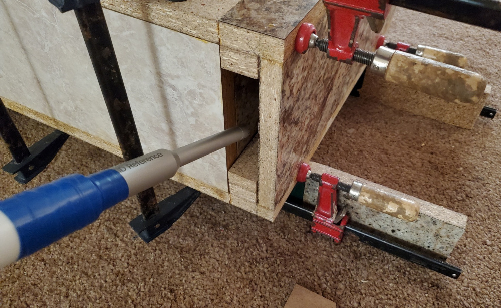
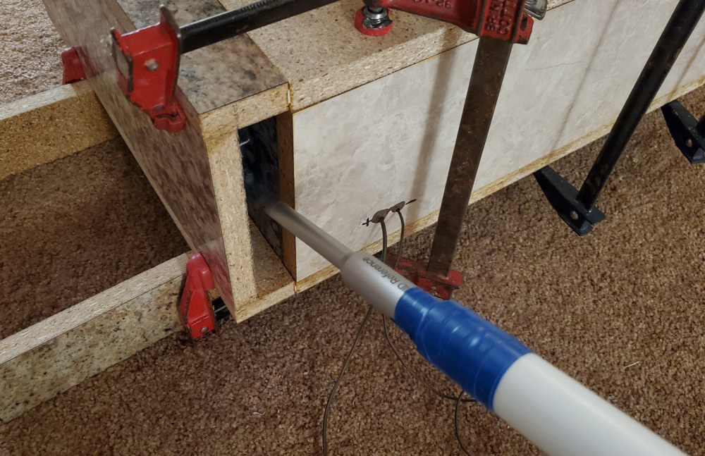
These were all near field (NF) measurements taken at the mouth of the two port openings. I then converted the two NF impulse files to FRD's using VituixCAD's conversion tool. Then, I summed the two FRD's using OmniMic's "added curves" and "sum" functions, and saved the resulting file to a new, combined FRD file. This gives me an accurate summation of the two port outputs with no phase or time delay applied to either measurement.
Thanks - that method sounds like the best to me.
Having seen ASR measurements of port resonances and mid-range port leakage, I am thinking that TLs and TL stuffing should greatly attenuate port output above Fs, and help make midrange frequencies "cleaner".
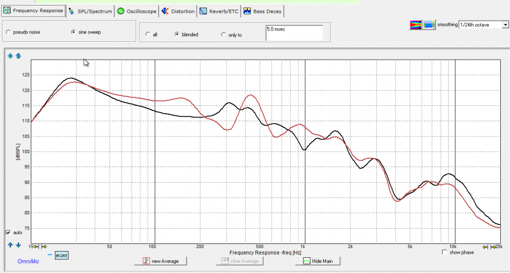
The measured response that peaks around 100Hz is strange, and may reflect some resonance that results from your unusual design. Here is a test I did comparing a BR port with a TL port - same box, same port, but one is a BR with lined walls and the other is a MLTL with stuffing. Somewhat surprising to me is that the output is virtually the same above 100Hz, but both show the characteristic port output peak at Fs. MLTLport in red, BR port in black.
But Chahly - Stahkist don't want speakers that look good, Stahkist wants speakers that sound good!
@Billet said:
Have you tried listening to each version with music that has a good bass line?
I have only listened to music with a good bass line on one test version so far. This was a completely unstuffed version, with 2.5" woofer offset, and a Dayton SPA250 plate amplifier installed. I varied the 24dB/octave crossover setting on the plate amp through various settings from 80 to 150Hz, took measurements, and listened to music with a heavy, deep bass line in the 20 to 40Hz region or so. The sound was very "punchy" and it hit the low notes with ease. Because there was no stuffing in the box, I think I could hear what sounded like a slap echo from the bass waves striking the hard walls in the undamped line. Or it could have been a chuffing noise caused by the screen material that I had stapled to the internal baffle board. (I had stapled screen door material over the baffle board to keep the stuffing from hitting the cone during the other tests).
I have not listened to any of the stuffed versions yet. This is something that I should have been doing as I go along. Thanks for reminding me.
@rjj45 said:
Thanks - that method sounds like the best to me.
Having seen ASR measurements of port resonances and mid-range port leakage, I am thinking that TLs and TL stuffing should greatly attenuate port output above Fs, and help make midrange frequencies "cleaner".
The measured response that peaks around 100Hz is strange, and may reflect some resonance that results from your unusual design. Here is a test I did comparing a BR port with a TL port - same box, same port, but one is a BR with lined walls and the other is a MLTL with stuffing. Somewhat surprising to me is that the output is virtually the same above 100Hz, but both show the characteristic port output peak at Fs. MLTLport in red, BR port in black.
I think you are correct about the 100Hz peaking. My educated guess is that this resonance is simply the result of the way I happened to set up this transmission line. This peak would probably not occur with a standard ML-TL type design. The reason I am getting this peak is because I am using a two transmission lines to create a somewhat narrow bandpass, and these two lines just happen to be peaking at the same frequency (100Hz or so).
Let's take an example. For test number 43, I stuffed the front and rear line sections with approximately 0.4 lbs/ft3 of denim material. Total line length, excluding ports, is 74.5" (68.4" on rear and 6.12" on the front section). The speed of sound is 1130ft/sec * 12 = 13560 in/sec /95Hz = 142.7" / 2 = 71.3" half wavelength.
Here is a graph of test #43 front, rear, and combined front + rear near field measurements. Notice how both individual front and rear curves peak up near 100Hz. My educated "fix" to this problem would be to 1) re-tune the front port to a lower frequency, and 2) reduce the length of the rear TL, which would cause the peak to move up to a higher frequency. Does that make sense? I'll give this a try and see what happens.
Bill, are both of the termini the same square area? I ask because you can't sum their mesurements together for accurate results if you don't account for the differences in areas. Just like driver and port NF summations.
@PWRRYD said:
Bill, are both of the termini the same square area? I ask because you can't sum their mesurements together for accurate results if you don't account for the differences in areas. Just like driver and port NF summations.
Good catch, Craig! The port termini were originally the same square area and when I re-tuned the rear port I forgot to make this adjustment. The front port is currently 7x1.25x17.1" and the rear port is 4.75x1.25x17.1" The rear port therefore needs to be reduced by 1.69dB before summation with the front port. I'll go through all my summed FRD's and make this correction.
New post by Martin J King and some (of course) very serious technical modeling. One of the take aways is that he expects to use acoustic foam in all his future builds. http://www.quarter-wave.com/Project13/Project13.html
But Chahly - Stahkist don't want speakers that look good, Stahkist wants speakers that sound good!
Comments
Update: I'm now up to test #17. Lots of frd's and zma's on file so far. On test #5, however, I blew the output chip on my DATS V2! Now it no long goes "whooooop" when I click the button. What happened is that, for each test, I connect the speaker leads to my amp and take NF mic measurements on the two ports. Then I disconnect the speaker from the amp, connect it to the DATS V2 leads, and run an impedance curve. On test 5, I accidently connected the DATS V2 to the power amp leads instead of the woofer leads by mistake. POW! My KLH power amp has about 32mV of DC offset at the output and that small amount of voltage instantly burned the DATS V2 output stage. I have a new IC chip on order from Mouser and when that comes in, I'll replace the burned out chip and see if I can get my DATS V2 to go "whooooop" once again! In the meantime, I'm using my WT3, which still works, but sometimes gives me garbage screens. I could also use my Arta jig to run impedance curves, but I have decided not to do so because I do not want to change my Steinberg UR22 gain settings between NF test measurements.
this should be very interesting
Man oh man, I have burned up so many dacs and mp3 players during speaker testing. Good luck on the replacement chip! Looking forward to the TL information dump!
In case anyone wishes to play along, here is a zipped up file of my first 31 test measurements, covering all woofer offset positions available. The "read me" file gives you everything you need to know to set up a model and run comparisons. I'm using the Leonard Audio TL program, but Hornresp might also be able to model this as a 6th order bandpass alignment. Any questions, feel free to ask.
Did you get your Dats fixed? What are they using for the output device?
Yup. All fixed up and working like new again. Probably blew the output transistors in the small SMT power amplifier chip when I accidently connected the leads to my power amplifier. My guess is that both DATS V2 leads must remain floating with respect to ground potential and when I accidentally connected it to my power amplifier outputs, for just a few seconds, this caused excess current to flow through the laptops 5VDC power supply ground connection.
Mouser sells this chip (Texas Instruments TPA6111A2) in two different size packages: SOIC (8) and MSOP (8). Both versions are 150mW Stereo Audio Power Amplifier chips. The SOIC (8) package has a 4.9 x 3.9mm body with 1.27mm ctr-to-ctr pin spacing. The MSOP (8) package has a much smaller 3 x 3mm body with a 0.65mm ctr-to-ctr pin spacing. Only the larger SOIC (8) package will fit the DATS V2 pad spacing. They are less than a buck each. Only 21,110 left in stock! I picked up 10 to get the quantity discount, so now I am ready in the event I make this dumb mistake again.
https://www.mouser.com/c/?series=TPA6111A2
Update on TL project:
It has been slow going on this project so far. I've been going over the data and have been having trouble getting a good match between model and actual measurements. The completely unstuffed models tend to look "similar" to the completely unstuffed actuals, but when I compare the stuffed LA-TL models verses the actual stuffed measurements, the match ups do not seem very good at all. And I have been unable to develop a stuffing "fudge factor" to account for the differences. I will continue testing to see what I can come up with. Have only tested standard poly-fil so far, but maybe other types will react differently.
Glad to hear you got it fixed! You must have used the fine tip on the iron for something that small.
IIRC, your TM had multiple cavities and a tunable woofer position.
It's very good that unstuffed models are similar to the unstuffed measurements.
You might try stuffing just a portion of the line(s) and see what happens.
This is how we have fun!
I have the Weller 1010 station and used their fine conical tip. And even then, I had trouble keeping the pads from shorting together. Used .032 60/40 rosin-core and "pre-liquified" the pads with MG chemicals 835 liquid rosin flux. Was a little "blobby" looking, but no shorts. The best way to do this type of small work is with a hot air re-work station, but I don't have one. You probably missed this, but here is a link to the other thread with a couple pictures of what the final result looked like:
https://diy.midwestaudio.club/discussion/2315/dats-v2-repair-attempt-successful#latest
I will give this a try and see what happens. Maybe I am jamming too much stuffing in the line. Maybe try putting just a little bit in at a time and then watch how the peaks and dips move around.
Progress report: I'm now up to test #42. Based on my analysis so far, I have pretty much come to the conclusion that a woofer offset distance of about 2 to 3 inches for FS1 produces the best looking unstuffed bandpass graphs. So I fixed the woofer at the 2.5" FS1 offset position and generated a few modelled verses actual measured FR comparison graphs. The variable is the amount of stuffing, ranging from no stuffing at all to a low of 0.2 lbs/cu.ft in some of the rear sections to a high of 1.2 lb/cu.ft. in some of the front sections. The average stuffing density in the charts below was approximately 0.2 lbs/cu.ft of poly fill for test "FR32" and 0.4 lbs/cu.ft of poly fill for test "FR34". Test "FR33" had no stuffing at all. The attached spreadsheet shows the detailed poly-fil stuffing density by line section:
First up, here is the completely unstuffed FR33 model verses actual frequency response. Looks like a fairly good agreement without stuffing, a little off on some of the peaks, but not too bad. Ignore the fact that this is not a very good bandpass at this point. My first goal is to match model to actual and then work on improving the shape of the bandpass:
Lightly stuffed (FR32, 0.2lbs/cu.ft poly-fil) model verses actual frequency response. There does not appear to be a good agreement from 50 to 200Hz between modelled and actual with light stuffing:
Moderately stuffed (FR34, 0.4lbs/cu.ft poly-fil) model verses actual frequency response. Again, poor agreement, this time at both higher and lower tuning frequencies:
Here are the LA-TL computer models comparing unstuffed (FR33), lightly stuffed (FR32, 0.2lb/f3 avg), and moderately stuffed (FR34, 0.4 lbs/cu.ft avg) transmission lines:
Here are the actual measurements comparing unstuffed (FR33), lightly stuffed (FR32, 0.2lb/f3 avg), and moderately stuffed (FR34, 0.4 lbs/cu.ft avg) transmission lines:
Finally, here is a comparison of the moderately stuffed actual (FR34) verses the lightly stuffed model (FR32). I did this comparison to see if an approximate 2X stuffing fudge factor would help the agreement. But it does not look much better.
Going forward, I will be repeating the comparisons above, but this time switching to the same lbs/cu.ft of Utratouch denim. I also did some testing using a SPA250 plate amplifier at various xover settings, to see how a plate amplifier could be used in combination with this bandpass alignment. Will show how that worked out in a future post.
Wow, you are really in deep! I suspect that LA-TL modeled unstuffed vs various stuffing graph is not that accurate. All the hornresp modeling I have done as well as measured show less bass response around Fs for moderate to heavy stuffing.
And about stuffing, I have never reconciled that Paul Kittinger usually uses about .75Lb stuffing per 1 ft^3, but hornresp usually models about 1/2 that amount (similar to your moderate stuffing density)
Another progress report: I switched over to Ultratouch denim damping material and ran up a comparison overlay to poly-fill stuffing using the same lbs/cu.ft. stuffing density and line dimensions. The problem with denim is that it is very dense compared to poly-fill and does not "tease out" as well. As a result, I was unable to do a comparison at my light stuffing density of only 0.2 lbs/cu.ft. Using an average line stuffing of 0.4lbs/cu.ft., however, I was able to "fluff up" the denim to fill the bottom 1/4 or so of the TL's cross sectional area. With poly-fil, I could tease it out and fill the entire cross sectional area at a density of 0.4 lbs/cu.ft. As a result, the response in the 20-40Hz region is at least 5dB higher using 0.4 lbs/cu.ft of Ultratouch denim compared to 0.4 lbs/cu.ft of poly-fill. The damping at higher frequencies above 150Hz, however, is about the same for both materials (see graphs below). So the ability to "fluff up" the damping material to fill the entire line significantly impacts the results. Simply lining the TL with a dense stuffing material at a rate of about 0.5 lbs/cu.ft. looks like a very good procedure.
So, first up, here is a comparison overlay of actual FR34 medium density (0.4 lbs/ft3) poly-fill stuffing verses actual FR43 medium density (0.4 lbs/ft3) Ultratouch denim stuffing. Note that the response is the same above about 150Hz, but below this the poly-fill stuffed line gives up about 5dB of SPL from 20-40Hz and about 3dB from 40 to 100Hz compared to denim.
I also tested a "heavy" filled line using Ultratouch denim (FR44), using an average line stuffing density of 0.78 lbs/cu.ft. In this case, I was able to "fluff up" the denim to fill the entire TL's cross sectional area. The result, however, was a loss of about 5dB SPL in the 20-40Hz region, compared to the same denim material stuffed at a rate of only 0.4 lbs/cu. ft. And above 150Hz, the LA-TL model does not agree very well with the actual measurement at all.
Here is a comparison of the modelled FR43 medium density denim stuffing (0.4 lbs/ft3) verses the modelled FR44 heavy density denim stuffing (0.78 lbs/ft3). The model and actual measurements show that over stuffing the line significantly reduces the SPL at all frequencies above 20Hz. Even though the curve looks the best overall, this is not what I want to do.
And here is a comparison of actual verses modelled FR43 medium density denim stuffing (0.4 lbs/ft3). Very poor agreement at all frequencies above 30Hz.
22ish to 100Hz looks really solid- LP to work with the rise +/- 100, maybe a 1st order to tie into a larger mid ?
Obviously you can over damp any any enclose with too much stuffing to the detriment of the sound quality - you need some resonance inside the cabinet to fill-out the sound.
Good data comparison with the two types of damping material.
Keep it coming - quite interesting . . .
Yes, it looks like a TL filled with denim at about 0.4 lbs/ft3 might work, but not without some type of active xover at 100Hz to deal with the rise. The rise in response is a function of the front port tuning in combination with the total length of the TL. If I move the front port tuning down from about 80Hz to 60Hz or so, this may help to soften the rising bulge at 100Hz. This will also reduce the passband at the same time, so the xover will have to be moved down from about 100Hz to maybe 75Hz or so. This is getting to be a very interesting rabbit hole, with lots of twists and turns!
Very interesting results - thanks!
Where did you measure the output?
I would normally expect better attentuation of frequencies over, say 200Hz to be much better in a TL vs a ported box.
These were all near field (NF) measurements taken at the mouth of the two port openings. I then converted the two NF impulse files to FRD's using VituixCAD's conversion tool. Then, I summed the two FRD's using OmniMic's "added curves" and "sum" functions, and saved the resulting file to a new, combined FRD file. This gives me an accurate summation of the two port outputs with no phase or time delay applied to either measurement.
Rear port output:
Front port output:
Have you tried listening to each version with music that has a good bass line?
Thanks - that method sounds like the best to me.
Having seen ASR measurements of port resonances and mid-range port leakage, I am thinking that TLs and TL stuffing should greatly attenuate port output above Fs, and help make midrange frequencies "cleaner".
The measured response that peaks around 100Hz is strange, and may reflect some resonance that results from your unusual design. Here is a test I did comparing a BR port with a TL port - same box, same port, but one is a BR with lined walls and the other is a MLTL with stuffing. Somewhat surprising to me is that the output is virtually the same above 100Hz, but both show the characteristic port output peak at Fs. MLTLport in red, BR port in black.
I have only listened to music with a good bass line on one test version so far. This was a completely unstuffed version, with 2.5" woofer offset, and a Dayton SPA250 plate amplifier installed. I varied the 24dB/octave crossover setting on the plate amp through various settings from 80 to 150Hz, took measurements, and listened to music with a heavy, deep bass line in the 20 to 40Hz region or so. The sound was very "punchy" and it hit the low notes with ease. Because there was no stuffing in the box, I think I could hear what sounded like a slap echo from the bass waves striking the hard walls in the undamped line. Or it could have been a chuffing noise caused by the screen material that I had stapled to the internal baffle board. (I had stapled screen door material over the baffle board to keep the stuffing from hitting the cone during the other tests).
I have not listened to any of the stuffed versions yet. This is something that I should have been doing as I go along. Thanks for reminding me.")
I think you are correct about the 100Hz peaking. My educated guess is that this resonance is simply the result of the way I happened to set up this transmission line. This peak would probably not occur with a standard ML-TL type design. The reason I am getting this peak is because I am using a two transmission lines to create a somewhat narrow bandpass, and these two lines just happen to be peaking at the same frequency (100Hz or so).
Let's take an example. For test number 43, I stuffed the front and rear line sections with approximately 0.4 lbs/ft3 of denim material. Total line length, excluding ports, is 74.5" (68.4" on rear and 6.12" on the front section). The speed of sound is 1130ft/sec * 12 = 13560 in/sec /95Hz = 142.7" / 2 = 71.3" half wavelength.
Here is a graph of test #43 front, rear, and combined front + rear near field measurements. Notice how both individual front and rear curves peak up near 100Hz. My educated "fix" to this problem would be to 1) re-tune the front port to a lower frequency, and 2) reduce the length of the rear TL, which would cause the peak to move up to a higher frequency. Does that make sense? I'll give this a try and see what happens.
Bill, are both of the termini the same square area? I ask because you can't sum their mesurements together for accurate results if you don't account for the differences in areas. Just like driver and port NF summations.
Great point Bill!
Good catch, Craig! The port termini were originally the same square area and when I re-tuned the rear port I forgot to make this adjustment. The front port is currently 7x1.25x17.1" and the rear port is 4.75x1.25x17.1" The rear port therefore needs to be reduced by 1.69dB before summation with the front port. I'll go through all my summed FRD's and make this correction.
New post by Martin J King and some (of course) very serious technical modeling. One of the take aways is that he expects to use acoustic foam in all his future builds.
http://www.quarter-wave.com/Project13/Project13.html