Site Links
Howdy, Stranger!
It looks like you're new here. If you want to get involved, click one of these buttons!
Quick Links
Categories
Who's Online (0)
Protection Cap for HiVi RT1.3WE Ribbon Tweeter . . .

I watched a tutorial video and made a spread sheet for calculating a protection cap but the subject tweeter has no Fs listed.
So, I assumed an Fs of 850 Hz for it with a low end XO at 2500Hz [recommended by PE at 12db/oct] and came up with 1650Hz as the cutoff Freq for the protection cap with a value of 17.85 uF.
[This tweeter will ultimately be XO'd above 4KHz in use in a 3 way,but the 2.5Khz number ^ used in the calculation is for testing in a 2 way XO].
Link to spec sheet --> https://www.parts-express.com/pedocs/specs/297-421--hi-vi-rt13we-spec-sheet.pdf
Link to video explanation of protection cap calculation --> 
Any feedback concerning this, please (Before I start any sweeps/testing this Musway DSP controller)?
TIA.
Comments
17.0uF NP Electrolytic caps installed on + lead to ribbons and moving forward . . .
This is my safety procedure:
Before making measurements play a test tone at 50 or 60Hz, and using a multimeter, set the output voltage to 0.283V (8 ohm nominal driver) or 0.2V (4 nominal driver)
Make sure amps are off when connecting drive units, whether they be tweeters, mids or woofers.
In the signal chain eg, PC, DSP, preamp etc turn things on.
But turn the amps on LAST.
But when turning off power. Turn the amp off FIRST.
You want a cap in series so it will block DC. (Edit- for justification)
Minimum size I would use is 10uF. But you can use whatever you have between 10-20uF. ( Some ribbon/planar tweeter manufacturers have recommendations on cap size- follow them. )
Do a frequency response measurement, starting at the manufacturers recommended crossover frequency. If there’s not recommendation start at 4KHz. Virtually all tweeters can handle 4KHz at 0.283V.
Now take a few different measurements at incrementally higher voltages. Ensure your sweeps last 5 seconds or less. Don’t do sweeps that last tens of seconds.
1% THD is generally the cutoff for an amplifiers limit. Some transducer manufacturers also use this for their tweeters lower limit. Seems sensible to me.
Once you’ve done this a few (dozen) times and played around with distortion measurements, you can refine your process. Or take shortcuts.
But it’s like driving; once you know how it can become second nature/automatic.
But that doesn’t stop you from making mistakes.
Accidents/Shit happens
Be kind to yourself.
Just to be clear, all caps (in series) block DC.
Agree.
I’ve always called it a “DC blocking cap”. I’m not trying to use it to tune my tweeter or provide a HP filter function. Is there a better term to call it?
Do you have anything to offer regarding the value of the capacitor that the OP requested assistance on?
Some people advocate for 20 or 30uF. But the exact value matters less if you follow the safety guidelines.
For the record.
I use no caps in my active system.
One can also drive a car with one hand, or apparently not at all in C21. But I’m not sure I could recommend it today.
Steve- this is one of those “Do as I say, not as I do” type of thing…
Don't know if you are using OmniMic to measure or not. I use OmniMic and when I measure planars (I have measured those RT1.3W) or ribbons I use the test track that has the bass removed and no series protection cap at all. I start the sweep with the volume knob all the way down. Slowly increasing the volume you can hear when the tweeter's distortion is rising to the point where you shouldn't go any higher. This is the point where I then take all my measurements for all the drivers, never changing the volume. I think the "bass removed" track starts the sweep at 500 Hz. That is plenty low enough to see the natural slope of the roll off and then add a tail with the same slope in the Blender program. That's how I do it anyway, and have never damaged a single ribbon or planar.
^What he said. Can't you simply start the sweep high enough in freq to avoid damage?
In REW you can set the starting frequency. However, when measuring the full speaker I have forgotten to change it after measuring my woofer from 5hz to 40Khz and just ran the same sweep at the same volume level on the tweeter. I haven't actually blown a tweeter either, probably because I'm using 1w or less. BUT if I was taking distortion measurements and did that (which is definitely something that I would accidentally do) then I'm pretty sure I'd fry a non-robust tweeter.
I have an active crossover I use inline with the amplifier.
My concern emanated from the high output levels of the default settings in the Musway DSP unit as I connected some old (I don't care if I blow them up) speakers to the DSP and amp to get my feet wet with the software and several times the sudden volume level made me jump out of my pants. The levels in the source audio (PC) changed after installing a driver. Like Thanh says - "Shit happens".
I think I will be fine with the 17uf cap and I have created a new default template file for the DSP that I will use for all future projects - it is set to keep all initial volume levels for inputs and outputs at the minimum value (-50db).
Additionally, I have set a default Butterworth High Pass XO value of 4Khz for all outputs as Thanh suggested.
Finally, Thanks to everyone who offered useful feedback.
This build is going to be fun to tune - I can just feel it . . .
That video is a really poor instruction TBH, calculate cap from driver Re? I guess that's better than nothing but..."there must be a better way".
You can trace, or better yet measure, the impedance of the driver, load the impedance into your favourite crossover simulation software. Add series capacitor to see exactly the effect it will have on the speaker output as well as the load that your amp will see. Adjust cap value as you see fit from there.
With dual channel measurement, insertion of protection cap can be compensated for in the measurement. For single channel users, it can be compensated for with the result of the above simulation. I could go into detail on that, but there's an even easier way. VituixCAD includes a protection cap compensation calculator tool. Just go to tools -> calculator and push the protection cap button, load measured FR and driver impedance, enter the cap value used for the measurements and compensation is complete.
All that said, I've yet to use a protection cap for any frequency response measurements for dome, planar or AMT drivers. Choose periodic noise instead of sine sweep if using ARTA, avoid using an amp with any turn on/off thump, avoid connecting RCA connections live. I would definitely use a cap if I ever use a true ribbon tweeter, but also requirement in that case for the amp load too. I wouldn't worry too much about destroying the Hivi planar, with only 1W into it should be very loud, way more than you need for a FR measurement, and more likely to damage from burning it out from power input than from low freq so you'd have to be doing something fairly silly to wreck it.
dcibel, the whole reason I actually brought this question/subject here is because I went, "Huh?", when he said the Re was the the way to calc the frequency - I always thought it was the impedance at the frequency that mattered and not the nominal or Re value.
Thanks for clearing that up for me and those silent folks trying to learn without making themselves look stupid.
As long as you stick to the ROT presented in the video of 2x Fs, calculation should be in the low impedance range for the tweeter, but you can still expect actual impedance to be a bit higher than Re.
Fs however has very little to do with the cap size consideration, and most tweeters will not present a nice textbook filter response since impedance varies over frequency, so will the filter transfer function. Tweeters with very flat impedance like planar or AMT are the exception. Tweeters with big high Q Fs peaks will be the worst offenders.
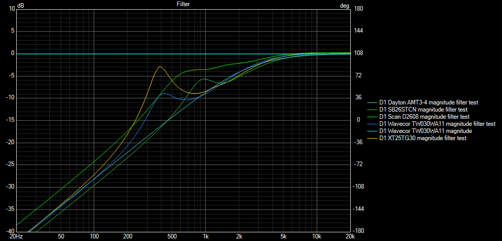
Depending on the tweeter, the same series cap can have very different results. Simple comparison of several 4 ohm tweeters and a 6 ohm Scan D2608.
With 17uF in series:
Doubled value to 34uF:
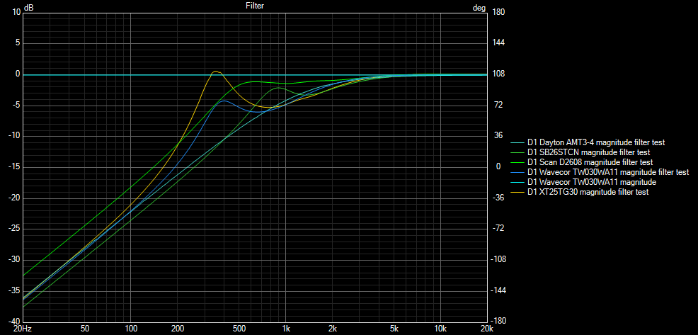
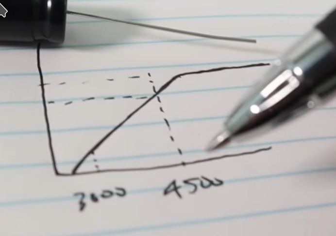
Looking at these simulations, you can see that the pen and paper response presented in the video is a bit optimistic, and the whole process is perhaps not the best method for a permanent car audio installation.
Mentioned above, in REW you can limit the sweep frequency range, unfortunately it is a hard stop. REW also has the ability to apply any EQ filter to the measurement (DSP style) so you can apply any filter transfer function to a driver for testing, keeping a perfectly consistent filter response between testing of multiple drivers. This filter response can then be compensated for by simple division of the measured response by the filter response.
It's under EQ -> Filter Tasks -> Measure with these filters.

Keep in mind that applying any protection via software or DSP does not protect the driver from amplifier on/off thumps, or from hum/buzz if a bad connection is made.
Are those peaks unique to each tweeter and caused by their respective resonance frequencies or an anomaly introduced by the series capacitor? (Asking for clarity of the purpose of the graphs).
Looks like my 17uf cap decision is good enough for the subject flat Z tweeter I am using when compared to the DaytonAMT3-4 graph above ^.
Excellent summation dcibel - thanks again for chiming-in.
It’s your turn now.")
The gold we dig for:
"@dcibel said:
You can trace, or better yet measure, the impedance of the driver, load the impedance into your favourite crossover simulation software. Add series capacitor to see exactly the effect it will have on the speaker output as well as the load that your amp will see. Adjust cap value as you see fit from there."