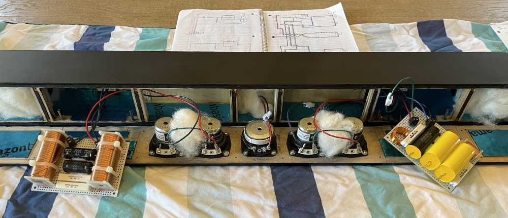
So I've pretty much settled on the crossover, and all I need to do is some more mocking-up and measuring to determine final phase tracking and impedance.
First order slopes were considered but discarded because the impedance fell too low. It would have been interesting since both these drivers have such a large passband.
Second order LR slopes at 400 Hz seemed to be the magic point. That's right where the HD of both drivers starts to change for the worse and so it was a natural target. That is also low enough that the polar response associated with lobing should be quite favorable, given the driver spacing.
Here is the topology and response without GEQ so the impedance is evident:
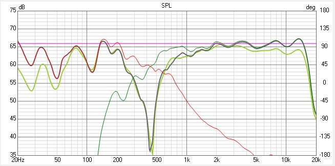
And here it is with my receiver's GEQ massaging it into shape:
The lowpass filter needed the LRC impedance compensation circuit to help drive down the room mode at 160Hz, but also to keep the impedance from dropping below 3 ohms. It also helps with the knee of the lowpass, given that the crossover point is so close to the driver's natural impedance bump.
I would have liked to keep the highpass filter simpler, but there was a bump at 3.5kHz that couldn't be fixed by the GEQ.
Measuring a reverse null at 400Hz is always going to be damn near impossible in my house, so phase tracking is a delicate affair of tracking that everything is doing what it is supposed to at the right points and then just knowing the simulation is right. The ND65x4 is delayed to the TA6 by 41us/14.2mm as measured empirically if you were curious.
Comments
TB 13-1761
Not seeing the SB models, but I know Nick got a set for the Minions.
InDIYana Event Website
So I've pretty much settled on the crossover, and all I need to do is some more mocking-up and measuring to determine final phase tracking and impedance.
First order slopes were considered but discarded because the impedance fell too low. It would have been interesting since both these drivers have such a large passband.
Second order LR slopes at 400 Hz seemed to be the magic point. That's right where the HD of both drivers starts to change for the worse and so it was a natural target. That is also low enough that the polar response associated with lobing should be quite favorable, given the driver spacing.
Here is the topology and response without GEQ so the impedance is evident:

And here it is with my receiver's GEQ massaging it into shape:
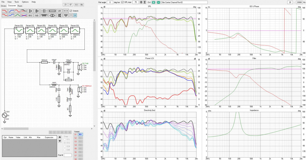
The lowpass filter needed the LRC impedance compensation circuit to help drive down the room mode at 160Hz, but also to keep the impedance from dropping below 3 ohms. It also helps with the knee of the lowpass, given that the crossover point is so close to the driver's natural impedance bump.
I would have liked to keep the highpass filter simpler, but there was a bump at 3.5kHz that couldn't be fixed by the GEQ.
Measuring a reverse null at 400Hz is always going to be damn near impossible in my house, so phase tracking is a delicate affair of tracking that everything is doing what it is supposed to at the right points and then just knowing the simulation is right. The ND65x4 is delayed to the TA6 by 41us/14.2mm as measured empirically if you were curious.
Cheers!
System HD with prototype crossover mocked-up:

Iron cored inductors were used for the LP section as well as NPE caps. I would have used poly caps if they would have fit!
Horizontal directivity curves:

Horizontal lobe analysis to confirm phase tracking:

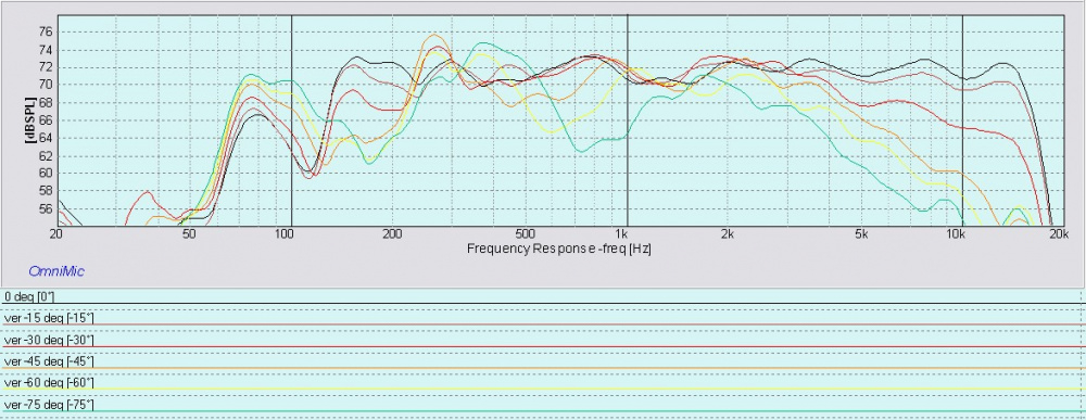
Vertical (up) directivity curves:
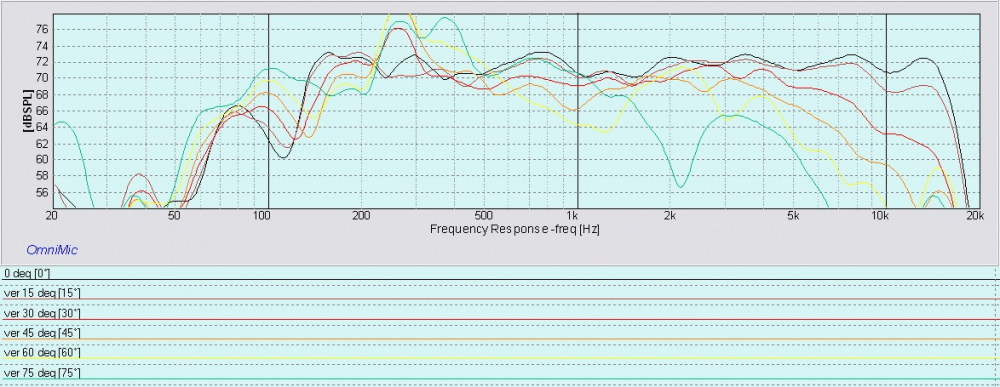
Vertical (down) directivity curves:
Cheers!
Crossovers completed:
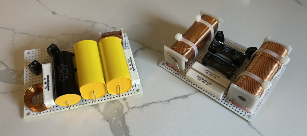
Jule Fidelity crossover components for the win!
Tight fit!
