Site Links
Howdy, Stranger!
It looks like you're new here. If you want to get involved, click one of these buttons!
Quick Links
Categories
Who's Online (0)
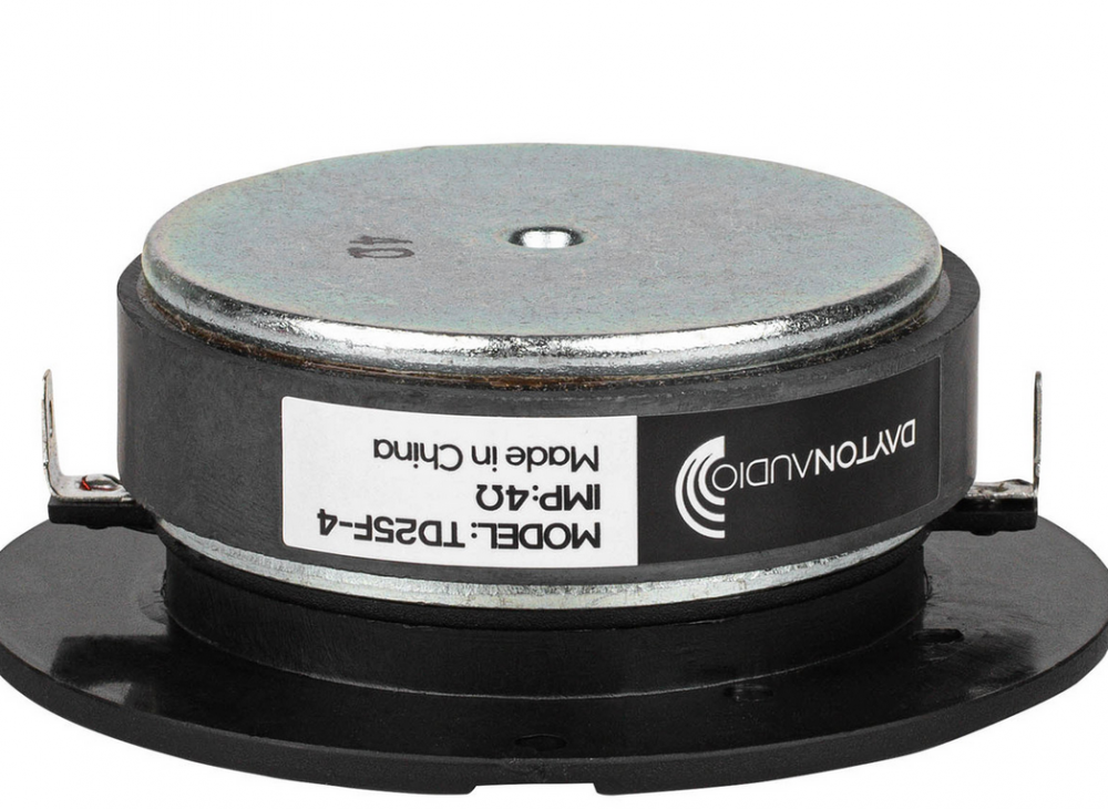
Dayton Audio TD25F-4 - some tests

The Dayton Audio TD25F-4 came up over the holidays when it was on sale for $11 or $13. Regular Price is $16.90. The discussion quickly ended due to its impedance curve.
PART 1: IMPEDANCE TESTS
Below is the published impedance curve by Dayton Audio.
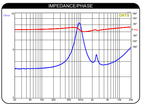
Given that they tend to pick favorable scaling and overly smooth their SPL curves, it is odd that they scaled the impedance from 2 to 10 ohms. I looked at a LOT of tweeters at Parts Express and Madisound and couldn't find anything zoomed in this much. Given that Dayton has the capability to design (in house, or outsource) good drivers, I wondered if this was even accurate. JR also noted that sometimes removing the faceplate and putting it back on can improve matters. So, I ordered a pair and played around with them.
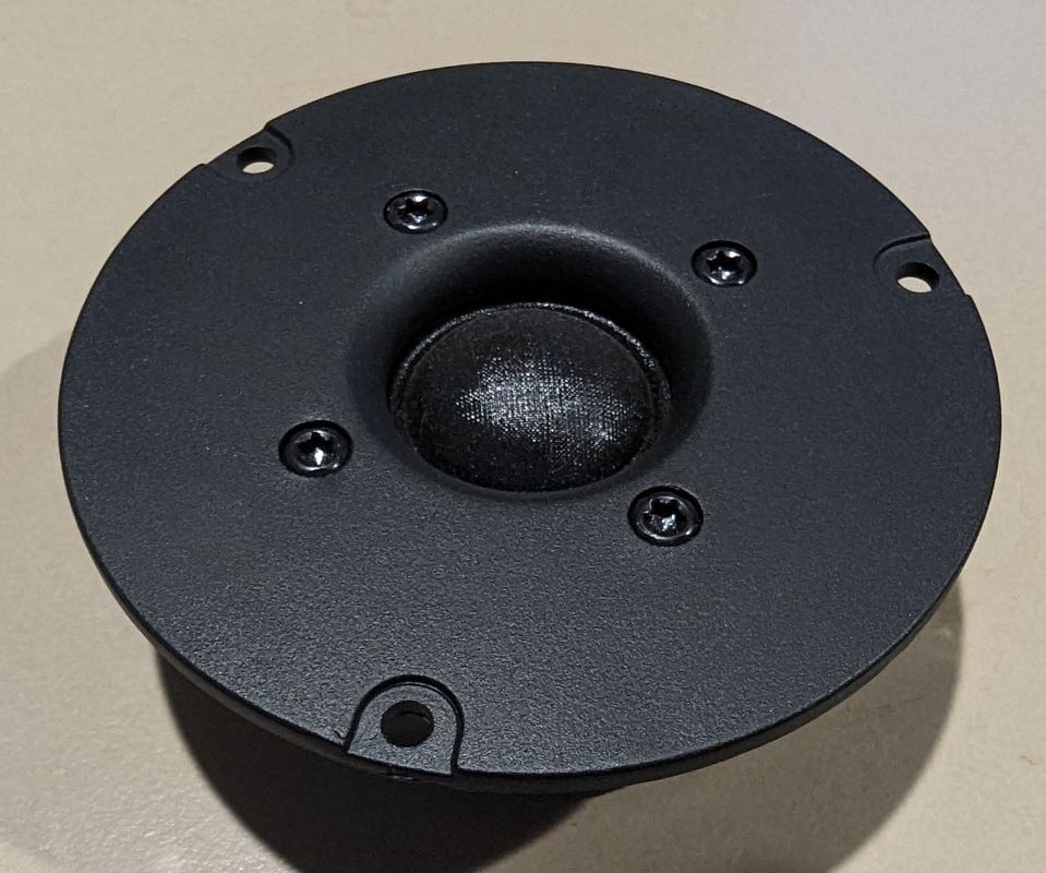
Tweeter...
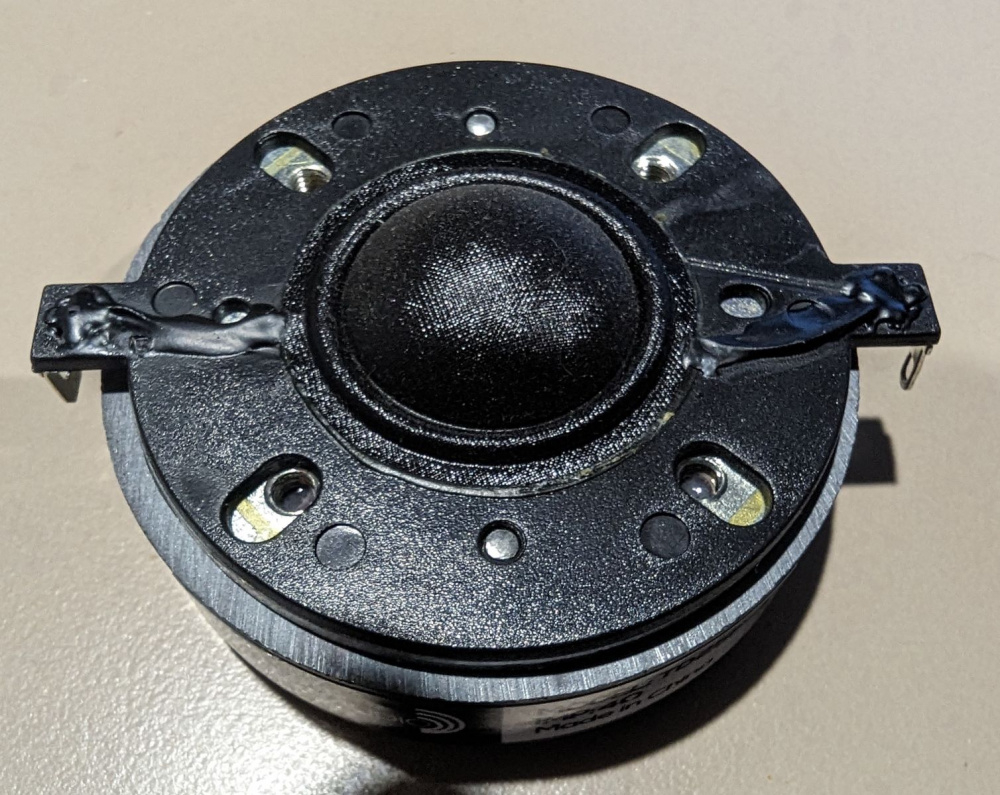
Without faceplate...
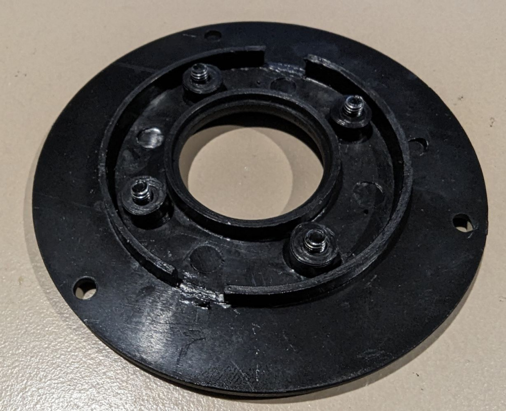
Just the faceplate...
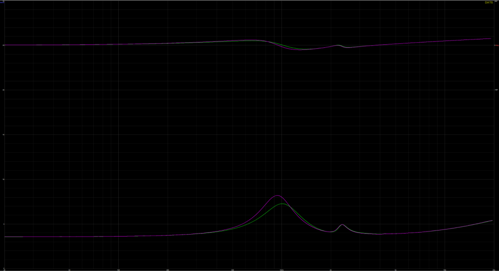
Here are the impedances for tweeter #1 and #2. (Impedance measurements using DATS v3) Yep, that spike is really there. Axis are hard to read...impedance is 0 to 30 ohms and frequency is 20Hz to 20Khz.
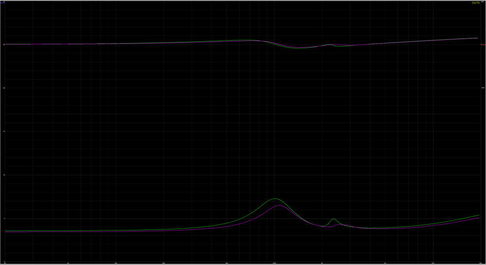
Here is the impedance for tweeter #1. Green line with the spike is stock tweeter. Yellow is with the faceplate removed and put back on, maybe a little tighter than orginal, but it didn't do much. Flatter green line (I couldn't figure out how to change the colors in DATS) is with the foam ring.
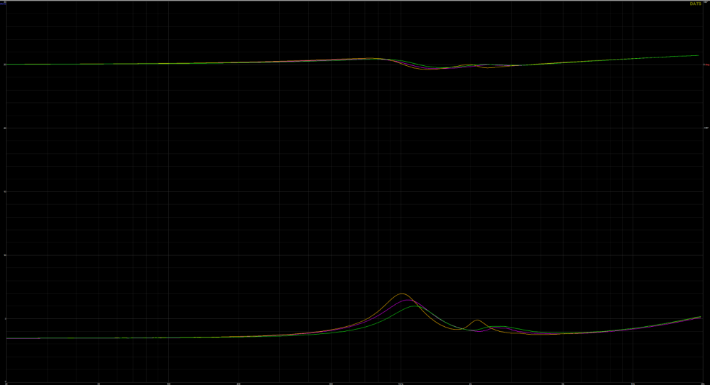
Here is the impedance of tweeter #2, same scenarios. Pink is stock tweeter. Orange is faceplate removed and put back on. Green is with foam ring.
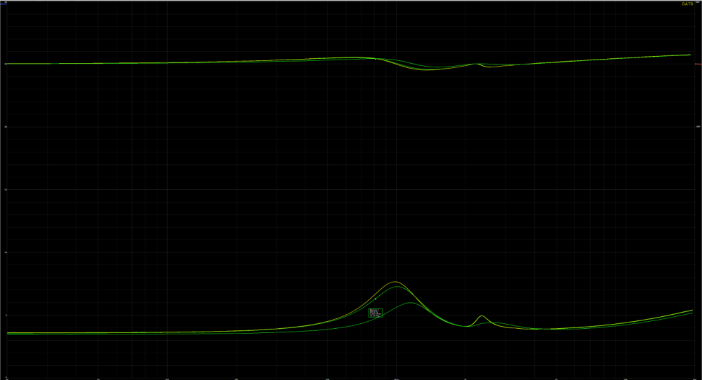
Here is impedance of tweeter #1 and #2 with foam ring.
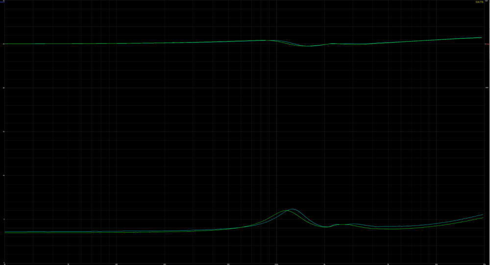
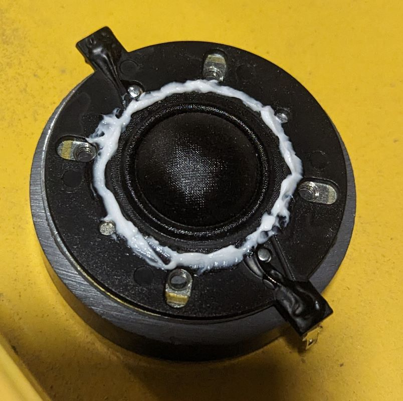
I thought the foam ring looked promising. So after all of the other measurements, I came back tried to seal it up even better using some DAP Kwik Seal caulk. It comes out white but dries clear. I also put a little gasket tape over the holes near the terminal connections.
I only did this with driver #1 and the results were unimpressive. Hopefully I can remove the caulk tomorrow. Stock tweeter green and caulked tweeter pink.
Comments
PART 2: SPL MEASUREMENTS
Okay, so the impedance blip really is there. Maybe adding some foam is worth it, not sure though for a $17 tweeter. So I took SPL and distortion measurements WITHOUT the foam ring. Here is the SPL per data sheet:
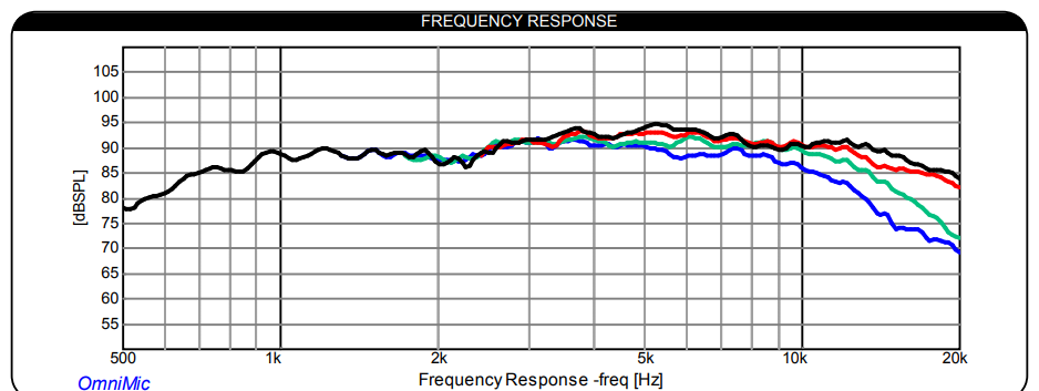
SPL levels on the graphs are roughly accurate, calibrated in REW with an SPL meter. FRD measurements taken at 1 meter, distortion measurements at 31.5cm, so deduct 10db to get the SPL at 1 meter. All on an fairly accurate IEC test baffle. Tested from 350Hz to 40,000Hz in REW and imported into VituixCAD because I like the presentation of the polar curves better.
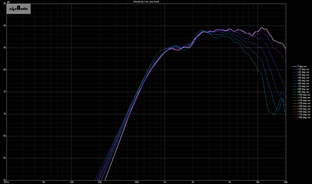
Tweeter 1 and 2 on axis.
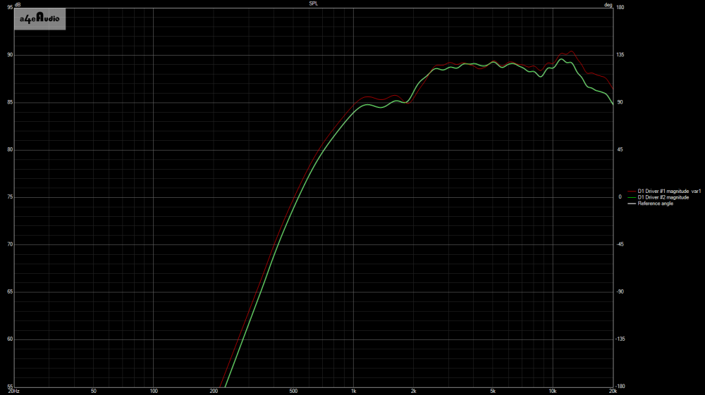
Tweeter 1 at 0, 15, 30, 45, 60 degrees.
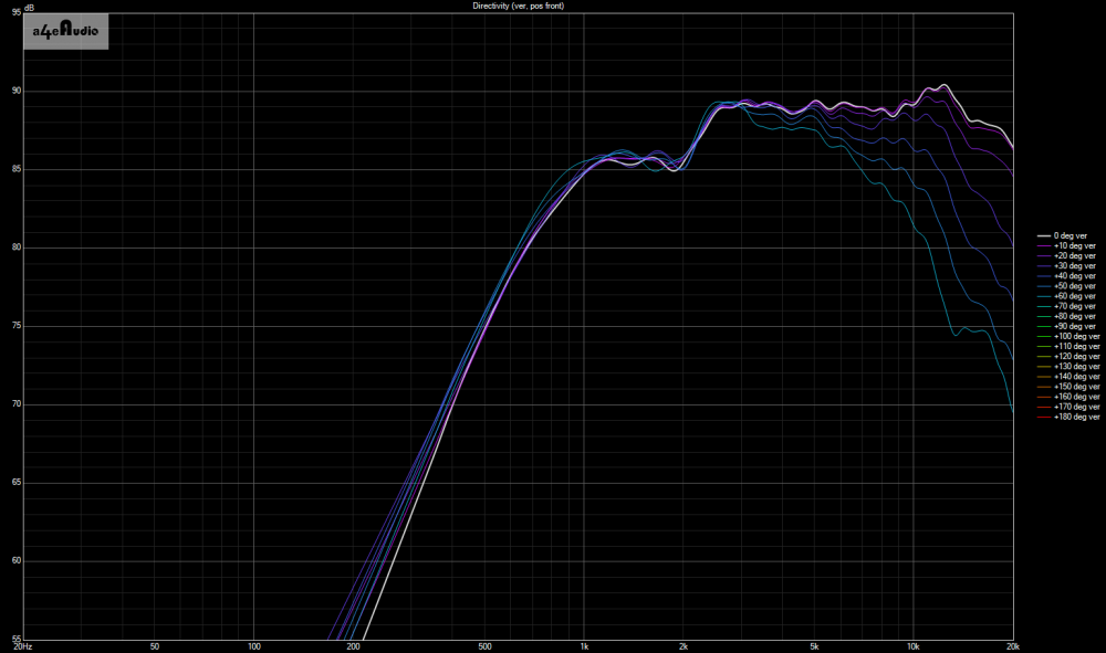
Tweeter 2 at 0, 15, 30, 45, 60 degrees.
Tweeter 1 distortion, roughly 86db at 1m
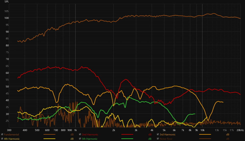
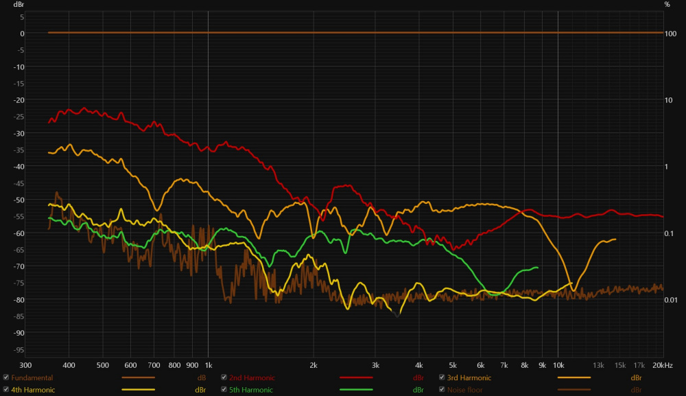
Tweeter 1 distortion, roughly 96db at 1m
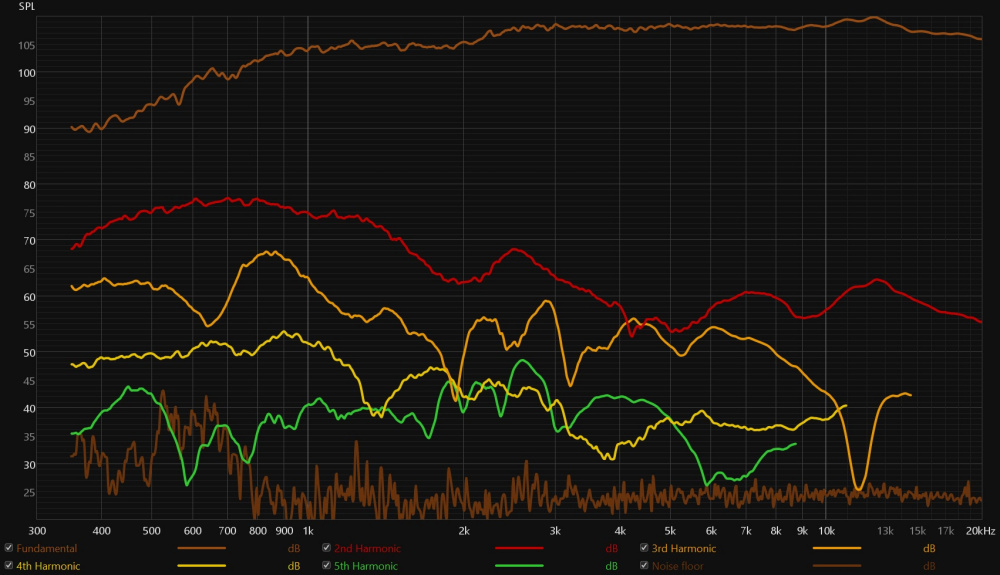
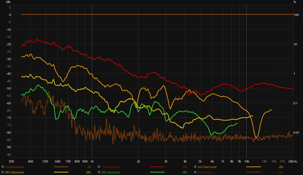
Tweeter 2 distortion, roughly 86db at 1m
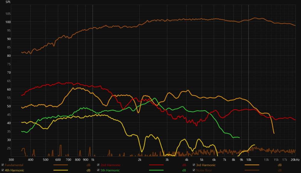
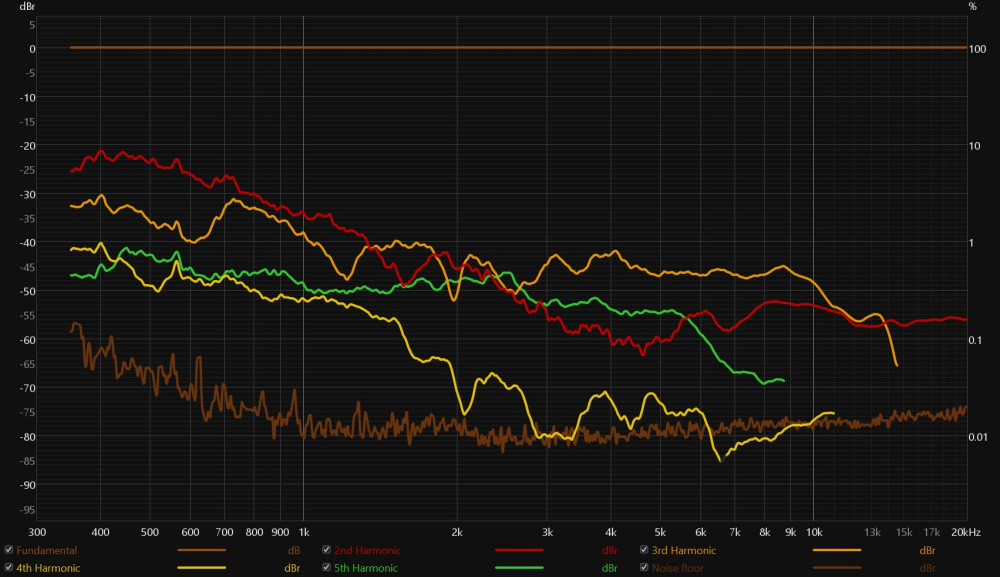
Tweeter 2 distortion, roughly 96db at 1m
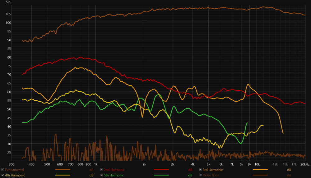
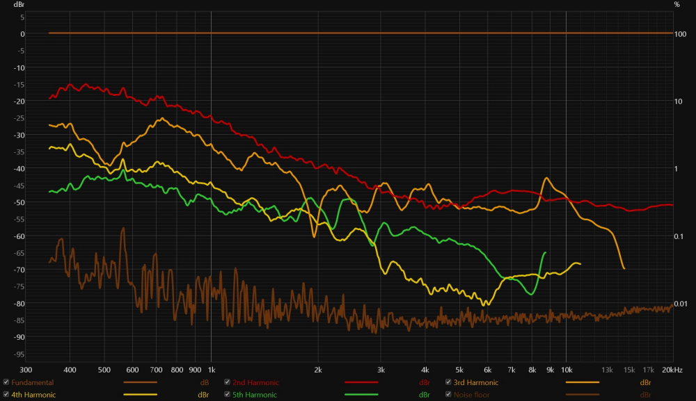
Little ragged around the edges, but distortion doesn't suck. Looks like a fine budget tweeter.
I wonder if there could be a leak on the backside of the tweeter. Does the tweeter diaphragm come of the motor? The impedance response looks like a ported box. I think there could be a leak on the backside.
Regarding the scaling change on the impedance graph. I imagine they get alot of returns from people running sweeps and seeing "unclean" graphs. Perhaps they wanted to be sure they made it as obvious as possible. Showing that it is an expected trait of the design rather than an anomaly of their specific shipped units.
I've used ARTA with a LIMP box to run continuous tests so I can see realtime what makes changes to impedance... I found the face plate or even small horns make almost no change (maybe shifting the frequency slightly). The position of the coil in the gap makes the biggest difference to the sharpness of the peak, but that is besides the point. Just showing why I doubt it is an issue with the diaphragm to faceplate seal.. I'd agree that it is likely a back seal issue. Removing and reinstalling the faceplate may just provide an additional chance to apply correct clamping pressure to get the back to seal up.
Possibly a smear of petrolium jelly could help? In the small ring of space between the coil gap and all the indexing lugs and screw holes. Sounds like a job for a q-tip.
Another thought.. The posts of plastic surrounding the screws on the back of the faceplate could be placing too much direct pressure causing the diaphragm plastic to warp like bacon and lose the seal. There are already inner and outer clamping rings molded in so possibly grinding down those posts a bit and being careful to apply even and limited torque to the screws could transfer more clamping force to the rings for more even application of pressure.
In the same price range is the HiVi SD1.1-A.
In the very limited reviews I've seen it is well liked. But I don't see it used much at all. Per Zaph it seems to also have a second impedance peak.
Poking at the thing with impedance RTA is definitely a good idea.
The faceplate is a bit unfortunate, with only a very small (1/16"?) ring pressure point against the diaphragm assembly. There's 2 alignment pins on the diaphragm assembly, so there's little risk to pull it off and inspect underneath, it'll be easy to pop the dome back on without a bunch of wiggling and jiggling. Possibly a gasket layer is absent as well between the diaphragm plastic plate and the motor top plate. Of the few domes I've disassembled, Vifa D27 had basically a thin paper gasket between there, Morel had nothing underneath, however a rather thick foam ring on the top side so there's plenty of pressure between the face plate and diaphragm assembling clamping it all together.
For this one, the first thing I'd try is a gasket layer installed on the inner ring of the faceplace. I would try sticking craft foam on there and cutting with a scalpel. That should add a good seal with some extra clamping force at that joint.
@dcibel or anyone else...
When I look at the normalized distortion at 86db to 96db, 2nd order distortion goes up, but 3rd order actually goes down. Is there a logical reason how that would/could happen?
I'd like to get good at measuring distortion, so would like to ensure I'm doing things correctly. However, my process was quite simple. I calibrated REW using an SPL meter and adjusted my amplifier and preamp to get to 90db (because the mfg specs list this tweeter as 91db 2.83v/1m). I measured the SPL measurements at that setting. Then I moved the mic to 31.5cm for distortion testing and just adjusted the Levels in REW to get 96db and 106db at 31.5cm. (Note, I only got to about 104-105 due to clipping. My Dayton Audio APA150 is my weak link right now. Preamp is Motu M2 and mic is Earthworks M23R.) Any comments on whether any of this is simply wrong, or if there is a better way to go about measuring?
3rd order distortion is caused by an asymmetrical movement of the diaphragm, possible the suspension components of the tweeter are more stable under a bit of movement. I don't really know beyond that.
For measurement process, it looks like you have a pretty good process down already. If you are calibrating with a handheld SPL meter, keep in mind that most handheld SPL meters are only about +/- 1.5dB accurate. Then for distortion measurements at 315mm, simply subtract 10dB to get SPL referenced to 1m distance. You can physically adjust the cablibration or just offset the measurements to show their SPL relative to 1m distance. Keep an eye on the headroom value in REW when measuring, it'll let you know how much increase in output you can make before clipping the input signal. Minimizing headroom will provide the best SNR, but you also want to ensure you have enough headroom to measure at the peak SPL the mic will see, so adjust the input gain accordingly and calibrate from there. I ran into a problem with a driver with 10dB breakup peak, it clipped when measuring at higher SPL even though the bulk of the measurement was -10dBFS.
I think there have been reviews of this dome saying it is a vented structure somehow. Was it Toid or Erin, IDK.
InDIYana Event Website
Is it a vent?
No, with regards to the faceplate somehow, obviously not the backplate.
InDIYana Event Website
This is exactly what I did in the picture above...wait...WTF...crap, that is what I get for posting at 1:23am ET. So, I did refer to adding a foam ring, and I did exactly what dcibel suggested, somehow I just didn't post the pic of the foam "gasket". And this was the one result that smoothed out the impedances a little, I showed this impedance curves above but will repeat here for simplicity (#1 and #2 with foam gasket).
Today, I removed the diaphragm assembly carefully with a utility knife. NO FOAM. I put some caulk around it and also around the alignment pins and screw holes. (The picture really overstates the amount of caulk, and I cleaned it up with a Q-tip to keep it away from the voice coil.) I also added back the foam gasket. I won't even post it, but the impedance was almost identical to the original stock tweeter before I did anything.
I probably give PE/Dayton more credit than some of you, but I figure they do have people that know what they are doing and if it was as easy as adding some foam they probably would have done that. So, I'm mostly done experimenting with them. I might play around with foam under the diaphragm assembly later and maybe even try a waveguide, the dome is not too tall and the surround is small, so it might be a good WG candidate. I'll probably build something for InDIYana and play it on Friday and see if the tweeter has potential as a good-value budget tweeter.
Ah, now those graphs and that “foam ring” mention makes a lot more sense")
I’m with you, probably not worth the effort, for a beer more there are some very well performing budget tweeters that you don’t need to fuss around with.