More on grounding. Have you read this LM3886 design write up from circuitbasics.com? It has some very interesting commentary about grounding near the end of the writeup that you may want to review:
I think Tom Christiansen of Neruochrome is close to "the authority" on the LM3886. Here are his articles on "Taming the LM3886" and Section 3 is on Grounding. Note, he also sells a PCB for his "LM3886 Done Right" amplifier.
Often best way that I have found is to combine output ground, amp circuit ground, power supply ground with transformer center tap ground often at chassis star/center point. Often signal level ground be left at the circuit board, typical input ground solder point. I've found sometimes board's output ground can just go directly to star ground. Sadly it is sometimes trial and error with someone else's board design, but often central/star ground yields the best results. If still noise, can twist toroid or see if the transformer is imposing a noise - but that is less common and often alleviated from good grounding to begin with.
In another example of an LM3886 design, the author separates the input ground from the other ground returns by connecting the input ground to the other grounds via a 2.2 ohm resistor paralleled with a 0.1uF capacitor. See R9 and C11 on the schematic in the linked writeup below: https://xtronic.org/circuit/amplifier/audio-power-amplifier-circuit-lm3886/amp/
It sounds like the simplist thing is to try leaving the individual board grounds "floating" with the center tap as their pseudo ground (as the traces are connected on the board). Then tie the incoming wall ground and transformer shielding to a single chassis point, and see what happens. The rest is all a bit much for my brain right now. Though it does seem potentially dangerous for other connected equipment to have a direct internal connection to the transformer.
Regarding the rectification: Their outputs will not be summed. They will be seperately powering each board individually because there is one rectifier built into each board. Though they will be sharing the same taps from the same transformer.
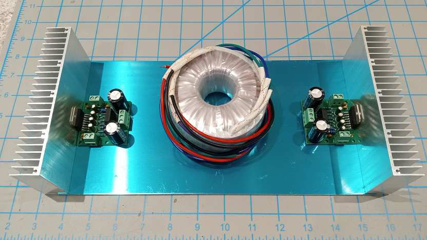
Back to the more fun stuff (for me atleast). Layout is pretty basic and spacious. Makes the 12"x6" aluminum plate seem huge.
I have used that same XY LM3886 amp board. It works just fine. I do suggest adding the Theil and Zobel filters to the output. Super simple to build and just gets wired between the amp's ouput terminals and the speaker jacks.
When you add the Theil and Zobel networks (cause I know you will) you can replace the cheesey 0.15 Ohm resistor that comes in the kit with a solid jumper wire.
Now I remember where I put those XY boards. I had an old Technics receiver that blew an STK pack after some major power bumps. The PS voltages worked out, so I just bolted them to the heatsinks. The Bass & Treble controls were in the feedback circuit of the STKs, so those are now useless. But those LM3886 kits saved it from the landfill.
Looking at this TDA7293 board I see a 10r and .1uf between output and gnd. So it atleast has something for a zobel. My cables shouldn't be too bad for capacitance.
This build just looking to swap out caps for something more reliable for starters then mod from there as needed. Placed the order already, but If it seems necessary I'll add the parts on the next order.
I haven't given it much listening time, but it sounds at least as good as the STK modules. It had been my desktop computer amp for 15 years. In all honesty, I just wanted to see if I could get those boards to work as an exercise in understanding the circuit.
I found these same heatsinks that I'm using on aliexpress for about half price compared to amazon and ordered 10x. I'll save a pair for myself, but if I make it to InDIYana I'd sell the rest pretty much at cost ($5 ea) if anyone is interested. I could maybe drill /tap a few 3mm holes too if I haven't already busted my tap before they arrive.
I just finished up soldering the new caps on. Rubycon electrolytics. I did end up bumping up the power supply filtering caps to 3300uf. Wasn't sure if the small ones were ceramics or dipped films so replaced with potted style WIMA and KEMET films.
I'm not used to electrolytics being so heavy. I do plan to use two of the mounting holes on the boards for standoffs. that should get the majority of the mechanical load off the chip leads.
A refreshingly simple project sofar. The angle aluminum chunks will hold screws to attach the front/back to the top/bottom. Yes the heatsinks are a bit blocked off. Debating leaving it as-is or using the router to cut a centered relief opening in the edges of the plates to expose some of the heatsink to vertical flow. Only using 18v transformer so limited wattage.
That's looking really cool! Get it running and see what the temps look like. I know the LM3875 stays cool unless it's running sine waves at 20 watts or more.
My mind got wandering.. I literally just used 6"x12" aluminum plates right out of the package with no modification besides drilling holes. If this works, the design would be dead simple to scale up to 4 channels. Use 12"x12" plates instead. Then stack on another set of heatsinks, amp boards and transformer.
One of the limitations is the heatsink height. The 200va antek transformers are too tall if you wanted to squeeze more juice from the chips. Though wouldn't be too hard to make some shims above/below the heatsinks. And, the heatsinks can be bumped out instead of recessed in order to accomodate extra transformer width.
Anyone have experience using switch mode power supplies with amps? Connex electronic makes some designed with amplifiers in mind. More compact and better regulation than just filter caps. Though possibly more shielding needed leading to active cooling requirements at higher loads?
I've built a few small "cigar box" amps using 19V laptop bricks, which are switch mode power supplies. They all worked really well. This is the little amp board I used:
@DrewsBrews said:
Anyone have experience using switch mode power supplies with amps? Connex electronic makes some designed with amplifiers in mind. More compact and better regulation than just filter caps. Though possibly more shielding needed leading to active cooling requirements at higher loads?
Neurochrome lists the SMPS300REh (±30 V) for their Modulus 86 amp.
And I'm pretty sure he used one for the 286 he shipped to ASR.
Smps are not nearly as noisy as they used to be. Many of them have really clean output as the switch mode frequency goes higher and higher with new technology.
The same technology that is used for SMPS is what is used in class D. I wouldn't be too scared. There are also ways to clean up dirty SMPS power supplies.
Not quite done but enough to test. I don't want to tempt fate and let the smoke out right before bed though
Don't mind the lack of chassis ground. I started wiring this evening before I realized I forgot to drill for a ground strap screw. So only the transformer internal shield is grounded currently.
I can pop some 8ohm resistors on the terminals. I've got a kill-a-watt to get an idea if it is oscillating and drawing excessive current at idle. Is it a good or bad idea to short the inputs to signal ground for first power test?
Comments
I had to look this up:
More on grounding. Have you read this LM3886 design write up from circuitbasics.com? It has some very interesting commentary about grounding near the end of the writeup that you may want to review:
https://www.circuitbasics.com/design-hi-fi-audio-amplifier-lm3886/#Things-to-Decide-Before-Starting
I think Tom Christiansen of Neruochrome is close to "the authority" on the LM3886. Here are his articles on "Taming the LM3886" and Section 3 is on Grounding. Note, he also sells a PCB for his "LM3886 Done Right" amplifier.
Often best way that I have found is to combine output ground, amp circuit ground, power supply ground with transformer center tap ground often at chassis star/center point. Often signal level ground be left at the circuit board, typical input ground solder point. I've found sometimes board's output ground can just go directly to star ground. Sadly it is sometimes trial and error with someone else's board design, but often central/star ground yields the best results. If still noise, can twist toroid or see if the transformer is imposing a noise - but that is less common and often alleviated from good grounding to begin with.
In another example of an LM3886 design, the author separates the input ground from the other ground returns by connecting the input ground to the other grounds via a 2.2 ohm resistor paralleled with a 0.1uF capacitor. See R9 and C11 on the schematic in the linked writeup below:
https://xtronic.org/circuit/amplifier/audio-power-amplifier-circuit-lm3886/amp/
It sounds like the simplist thing is to try leaving the individual board grounds "floating" with the center tap as their pseudo ground (as the traces are connected on the board). Then tie the incoming wall ground and transformer shielding to a single chassis point, and see what happens. The rest is all a bit much for my brain right now. Though it does seem potentially dangerous for other connected equipment to have a direct internal connection to the transformer.
Regarding the rectification: Their outputs will not be summed. They will be seperately powering each board individually because there is one rectifier built into each board. Though they will be sharing the same taps from the same transformer.
Back to the more fun stuff (for me atleast). Layout is pretty basic and spacious. Makes the 12"x6" aluminum plate seem huge.
You should be fine using the rectifiers as separate power supply circuits, Drew.
Sorry, late to the party. Rather than squize everything on those little boards you could use the other power supply board: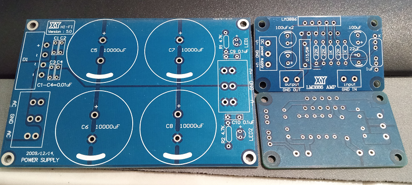
I have used that same XY LM3886 amp board. It works just fine. I do suggest adding the Theil and Zobel filters to the output. Super simple to build and just gets wired between the amp's ouput terminals and the speaker jacks.
Make sure those PCBs and stuffed boards have Zobels, or be prepared to add them to each channel
When you add the Theil and Zobel networks (cause I know you will) you can replace the cheesey 0.15 Ohm resistor that comes in the kit with a solid jumper wire.
Now I remember where I put those XY boards. I had an old Technics receiver that blew an STK pack after some major power bumps. The PS voltages worked out, so I just bolted them to the heatsinks. The Bass & Treble controls were in the feedback circuit of the STKs, so those are now useless. But those LM3886 kits saved it from the landfill.
How does it sound Tom?
Looking at this TDA7293 board I see a 10r and .1uf between output and gnd. So it atleast has something for a zobel. My cables shouldn't be too bad for capacitance.
This build just looking to swap out caps for something more reliable for starters then mod from there as needed. Placed the order already, but If it seems necessary I'll add the parts on the next order.
I don't know anything about those TDA7293 boards. I was only referring to the XY LM3886 boards. But your build looks awesome so far:
I haven't given it much listening time, but it sounds at least as good as the STK modules. It had been my desktop computer amp for 15 years. In all honesty, I just wanted to see if I could get those boards to work as an exercise in understanding the circuit.
I found these same heatsinks that I'm using on aliexpress for about half price compared to amazon and ordered 10x. I'll save a pair for myself, but if I make it to InDIYana I'd sell the rest pretty much at cost ($5 ea) if anyone is interested. I could maybe drill /tap a few 3mm holes too if I haven't already busted my tap before they arrive.
They are very close to 6" long. So almost exactly line up to these:
https://amazon.com/dp/B09NLWS8KK?ref=ppx_yo2ov_dt_b_product_details&th=1
I just finished up soldering the new caps on. Rubycon electrolytics. I did end up bumping up the power supply filtering caps to 3300uf. Wasn't sure if the small ones were ceramics or dipped films so replaced with potted style WIMA and KEMET films.
I'm not used to electrolytics being so heavy. I do plan to use two of the mounting holes on the boards for standoffs. that should get the majority of the mechanical load off the chip leads.
A refreshingly simple project sofar. The angle aluminum chunks will hold screws to attach the front/back to the top/bottom. Yes the heatsinks are a bit blocked off. Debating leaving it as-is or using the router to cut a centered relief opening in the edges of the plates to expose some of the heatsink to vertical flow. Only using 18v transformer so limited wattage.
That's looking really cool! Get it running and see what the temps look like. I know the LM3875 stays cool unless it's running sine waves at 20 watts or more.
Sweet and clean! I agree - run it at "normal" levels and check for heat.
My mind got wandering.. I literally just used 6"x12" aluminum plates right out of the package with no modification besides drilling holes. If this works, the design would be dead simple to scale up to 4 channels. Use 12"x12" plates instead. Then stack on another set of heatsinks, amp boards and transformer.
One of the limitations is the heatsink height. The 200va antek transformers are too tall if you wanted to squeeze more juice from the chips. Though wouldn't be too hard to make some shims above/below the heatsinks. And, the heatsinks can be bumped out instead of recessed in order to accomodate extra transformer width.
Only time will tell if you can get along with shorter heatsinks. I used some big ones on my Gainclone, and they seldom got even a bit warm.
Anyone have experience using switch mode power supplies with amps? Connex electronic makes some designed with amplifiers in mind. More compact and better regulation than just filter caps. Though possibly more shielding needed leading to active cooling requirements at higher loads?
I've built a few small "cigar box" amps using 19V laptop bricks, which are switch mode power supplies. They all worked really well. This is the little amp board I used:
https://www.parts-express.com/TDA7492-Digital-Audio-Amplifier-Board-2x50W-320-606?quantity=1
Neurochrome lists the SMPS300REh (±30 V) for their Modulus 86 amp.
And I'm pretty sure he used one for the 286 he shipped to ASR.
Smps are not nearly as noisy as they used to be. Many of them have really clean output as the switch mode frequency goes higher and higher with new technology.
The same technology that is used for SMPS is what is used in class D. I wouldn't be too scared. There are also ways to clean up dirty SMPS power supplies.
Not quite done but enough to test. I don't want to tempt fate and let the smoke out right before bed though
Don't mind the lack of chassis ground. I started wiring this evening before I realized I forgot to drill for a ground strap screw. So only the transformer internal shield is grounded currently.
I can pop some 8ohm resistors on the terminals. I've got a kill-a-watt to get an idea if it is oscillating and drawing excessive current at idle. Is it a good or bad idea to short the inputs to signal ground for first power test?
Short the inputs to ground.