Site Links
Howdy, Stranger!
It looks like you're new here. If you want to get involved, click one of these buttons!
Quick Links
Categories
In this Discussion
Who's Online (0)
Isobaric, how to actually do it?

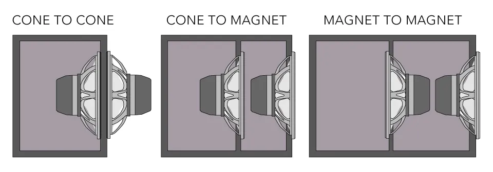
Okay, I know the theory behind Isobaric, I have seen lots of line drawings of Isobaric woofer setups, "cone to cone", "magnet to magnet" and "cone to magnet", but very few real life build examples, expecially in non-subwoofer applications.
Since I am looking to build a multiway full range speaker and not a subwoofer, the easy "cone to cone" is off the menu and I will instead have to do "magnet to cone".
My question really comes down to the size of the physical chamber between the two woofers and properly "venting" the front woofer.
I don't know how increasing the chamber size between the two woofers to allow for front woofer venting effects coupling between the two woofers.
Does a larger chamber between the woofers decrease the coupling effect due to air compressability?
I would expect the smaller the chamber the better, but the chamber needs to be large enough to allow proper front woofer venting so it can breathe.
Also playing into this, since there is a mid woofer above the pair of isobaric woofers, a larger coupling chamber between the woofers increases the
centre to centre spacing between the woofer and the mid woofer above it.
My guess, and I think what I will go with is, as large a chamber as required to allow for normal rear venting on the front woofer as I would do on any other build, ignore the larger center to center spacing that that forces and deal with it in the crossover. The C-C not being as important as it would be in a two way, because the XO point is going to be in the 100's of Hz and not >1000Hz.
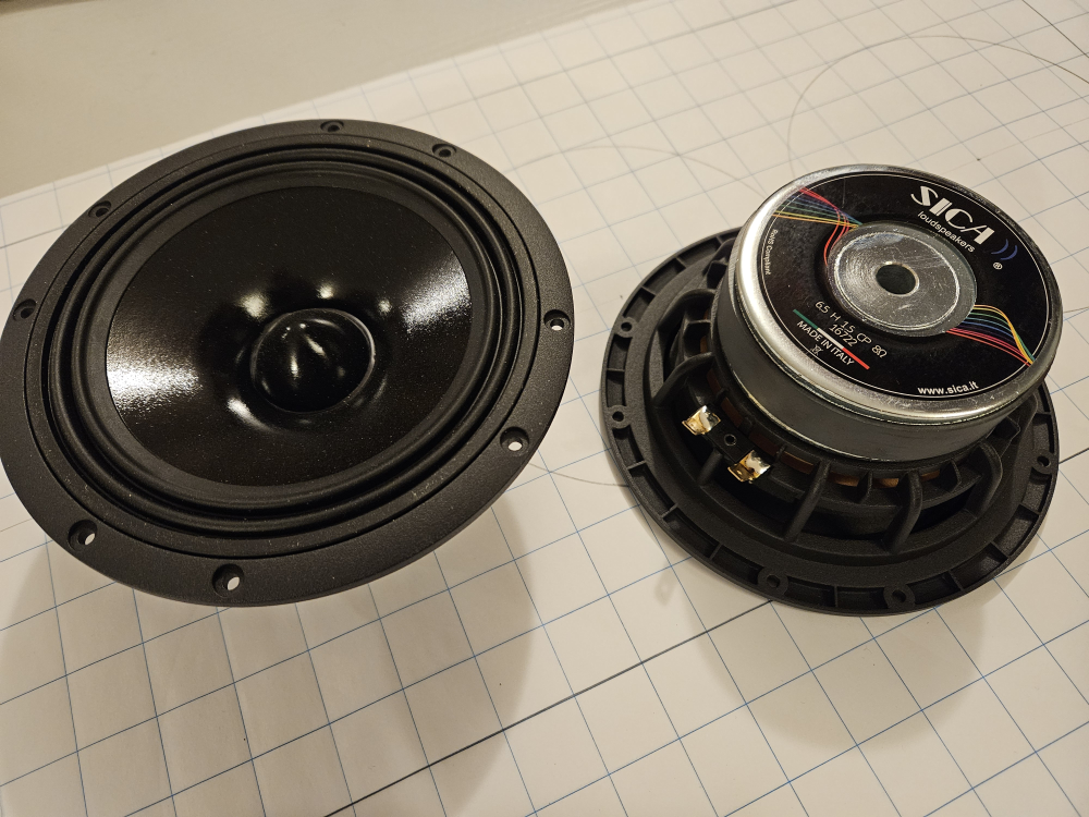
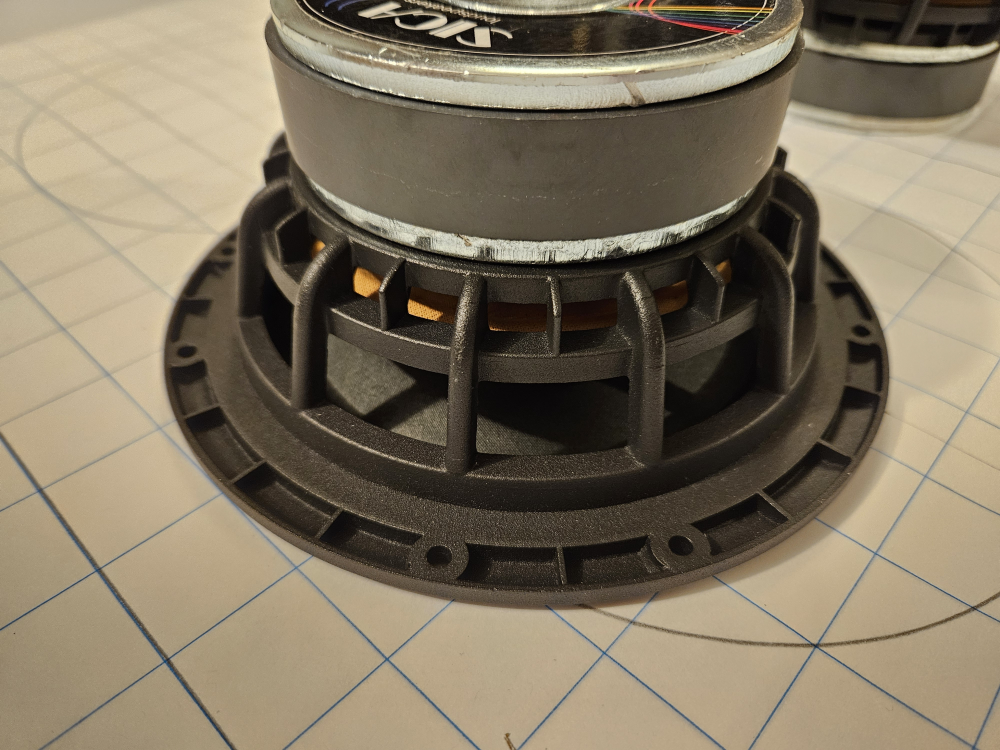
Shots of the 7" woofers in question to show how closed the frame is and various Isobaric configs.
Thoughts on my rambling post?
Best Answer
-
I have used the standard white/clearish hot melt glue several times to pass wires into mid chambers. Works great and never had any issues with it.


Answers
Your post content is right on the money and I have the same curiosity so I will be watching for the feedback as it comes-in. Those look like some nice drivers, too.
For my isobarics:
These decisions were based on other people's posts and their intuitive guesses, but I could not find any actual measurements or evidence to support anything one way or the other.
There is a PDF in the first post of THIS THREAD and there is a description and (not great) pictures in the first 6 pages of the PDF.
Opposing configs (cone to cone, or magnet to magnet) aparently have the potential to reduce odd order harmonics, but those aren't the "bad" harmonics anyway so often cone-to-maginet is the most practical.
The air in the chamber between adds to the moving mass of the total pair, which can effect the tune, so keeping this space as small as possible can be useful.
IMO just be mindful of "breathing room", but don't be too constrained by it in relation to the mid. You can open it up a bit for the other sides to compensate a little. If you build the mid enclosure out of the same material you can just use the top of the iosbaric chamber as the bottom of the midrange chamber.
Speakers are always a compromise of some sort.
Bad link ^ David?
http://https//diy.midwestaudio.club/discussion/2213/bosi-225-a-2023-indiyana-build-satori-tw29rn-8-dayton-audio-rs225-8-isobaric
Link says it cannot be reached for me.
Thanks for the alert, it should work now.
@DrewsBrews
Hold on - I thought the odd order harmonics were definitely the "bad" ones.
2nd order isn't noticeable because it is an octave about the fundamental..
Or am I wrong?
I am of the same understanding, rjj45 - odd order are mostly mechanical and bad where-as even order are natural occurrences and necessary to round out the reality of the sound.
lol yep I got myself mixed up
Does isobaric alignment just make the pressure output of the drivers roughly double that of a single driver while keeping air volume displacement the same as a single?
Yes. It cuts VAS in half. The other T/S parameters remain the same. I've built a few isobarik two way speakers over the years. Here is a link to page 3 of my Zonker thread, which has a discussion of how the isobarik tunnel spacing distance affects (or does not affect) the frequency response measurement with and without the internal woofer connected.
https://diy.midwestaudio.club/discussion/1513/the-zonkers-an-isobarik-8-two-way/p3
Excellent.
So for near-field the isobarics will sound punchy in the bass where in mid to far field the bass will be weaker than 2 parallel woofers on a baffle.
(I have it my my mind [that my body cannot keep up with] using a SEOS-8 wave-guide with a JF1204F tweeter and a pair of isobaric MCM-5670's as a possible future project as a result of this discussion).
Alternatively, a pair of Celestion TFX0615 coaxes using the same isobaric mounted MCM-5670's to create a bit larger 3-way.
With isobariks, you will get roughly the same low frequency alignment in a box that has only half the volume. Also, the isobarik system will have less cabinet surface area and therefore less sound will be generated by the entire external surface area of the box. Even with lots of bracing, all cabinets vibrate and generate sound. The larger the cabinet, the greater the sound.
Bill, remember of discussion several years ago about increasing the distance between the woofers adds a reflection blip in the response.
Yes, I remember that discussion. My thinking at the time was that at a certain distance, based on 1/2 wavelength and the speed of sound, that there would be a 180 degree out of phase condition between the inner and outer isobarik woofers. I called this the "iso-null" For instance, if the spacing distance between the inner and outer woofers is 2.5 inches, then the "iso-null" would occur at 2712Hz (((1130*12)/2.5)/2). At the time that I developed this idea (Speaker Builder magazine, 5/90) I was using a Stereo Review warble tone test record and a Radio Shack SPL to do my measurements. Turns out that I was actually measuring room modes back in 1990 and not the isobarik speaker itself. So my conclusions about the "iso-null" were somewhat wrong. My recent gated type measurements on my Zonker speakers showed something completely different. What is actually going on between the two woofers in an isobarik chamber is much more complex. Good measurements will tell you this.
If there is still any grey area on the basics... Here is a video that cemented things pretty well in my head.
The only nitpick is he does not specify any more than "db". It appears he is specifically talking about db/watt, though we tend to be more concerned with voltage sensitivity when mating to other drivers. Because of the wiring configs they would all have identical voltage sensitivity.
I figure you TL guys might be interested on his comments towards the end (~6min mark).
Another video with comparisons of alignments, less math, more result sweeps:
What what do you think the best "pass through" binding posts would be?
I am thinking of just some brass bolts and nuts...
Were it me. I'd just drill a small hole, pass the wires through then seal with silicone.
The wires are a PITA from the outside woofer. They need to be short enough where they don't hit the inside woofer but long enough to connect the woofer. I minimized the chamber volume so it was tight. I ended up pulling the excess wire through a double thickness foam gasket on the flange where the inside woofer mounted.
Any thoughts on hot melt glue as a way to seal the wire?
Yep. I don’t use the clear ones I use the ones that look like wood glue on a stick as far as I know the yellow ones are great and they stick very well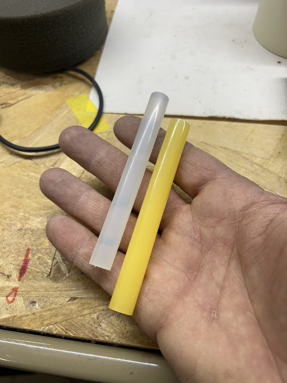
https://www.jfcomponents.com/
I always used silicone, just make sure it's dry before you assemble as the outgasses can affect some other glues.
Let's see...
E6000
Dap Kitchen Caulk
RTV
Epoxy
There are many ways to do it....
You could even use a metal contact of one sort or another, and solder on both sides. Some flat foil coil leads would easily glue under the chamber wall if they were left over from a previous project.
InDIYana Event Website
Thanks Ben, I figured there was umpteen ways to do it, I was just specifically asking if there was some inherent drawback to using hot melt glue that I have not foreseen, i.e. shrinkage, etc.
I think I will try the clear hot melt glue I have, it seems like it would be removable with some work, but wouldn't tear parts of the wood. The wire passes through 1" of ply, so I will just try to inject lots in from both sides. Also seems like the white is a little rubbery.
Thanks, David.
+1
I have had hot glue fail one time (that I know of) in a car subwoofer. I used to work at a car audio shop and when a customer didn't want terminals we would just drill a hole, tie a knot, and hot glue the knot to the board. I don't think it would ever be an issue with anything home audio.