Site Links
Howdy, Stranger!
It looks like you're new here. If you want to get involved, click one of these buttons!
Quick Links
Categories
In this Discussion
Who's Online (0)
Some VituixCAD tips

I'm probably not the best person to be offering VituixCAD tips, but I am good at taking screenshots and putting red, green, blue circles around relevant items, so this is my attempt.
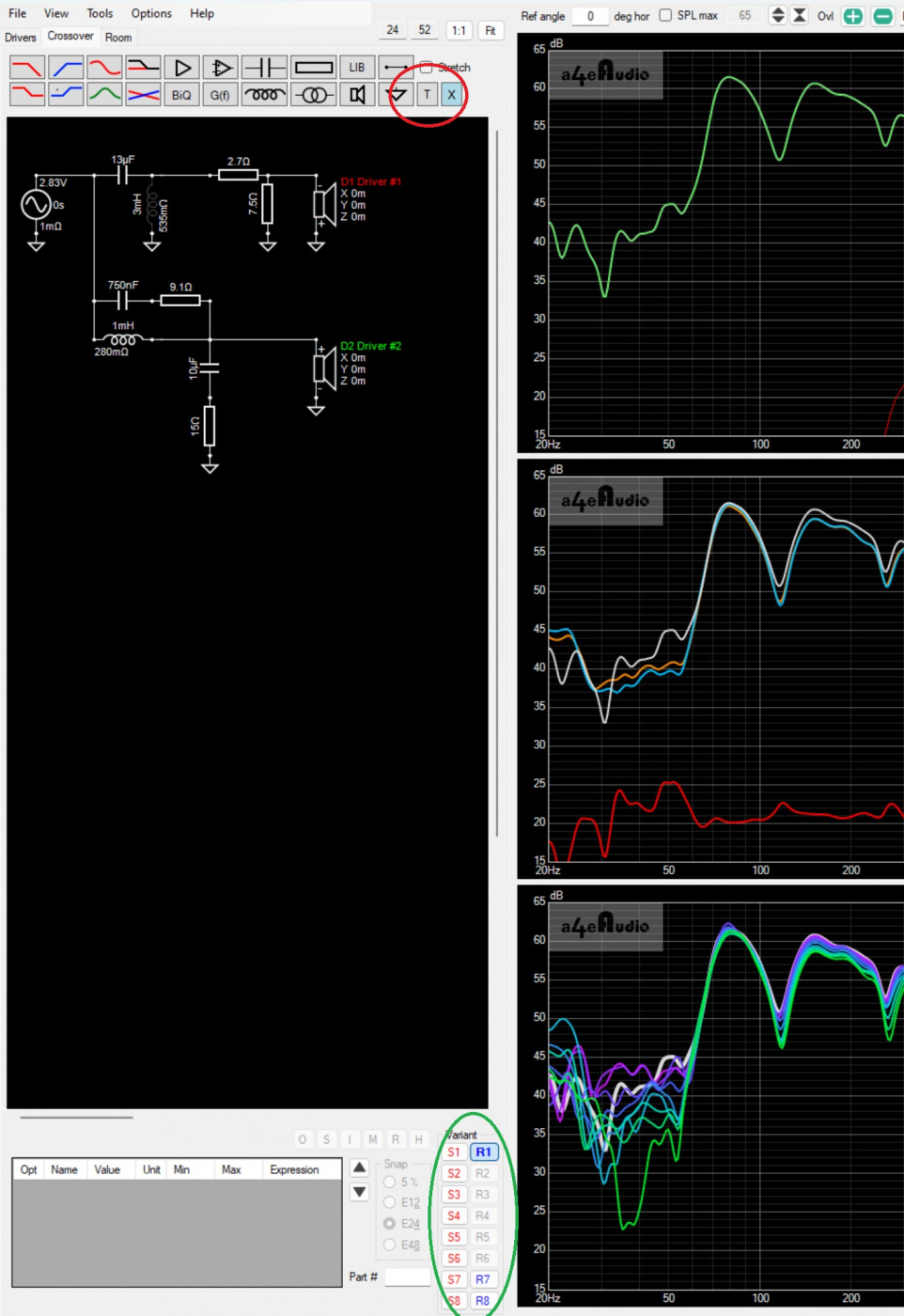
One of the best features of VituixCAD is the ability to save 8 variants of crossovers (green circled area) and add text comments (red circled menu button).
I usually start by loading the raw tweeter, midrange and woofer in variants 6 ,7 8 so I can see areas of interest (directivity, peaks, dips, breakup, etc.) without any crossover in place. When I start attempting crossover variants I add comments such as, "Target LR2 @ 2khz", Target LR4 @ 2.3khz", "Need to fix phase", "Fixing impedance", etc. so I can remember in a week what I was thinking at the time.
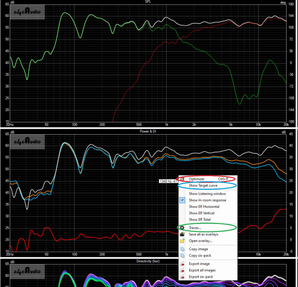
If you right-click in one of the window areas a drop-down menu appears (it will have slightly different options depending on which pane of the six-pack you are hovered over). Obviously there are several items, but here you can choose to show/hide target curves (green circle), select preferences for traces (red circle), etc. I like to change the target curves to 4pt width magenta. In the screenshot below I have chosen to show the target curve and show Listening Window (bright green line in SPL window).

The Optimizer menu allows you set LOTS of different targets. Right-click on a window pane and select optimizer (red circle below).
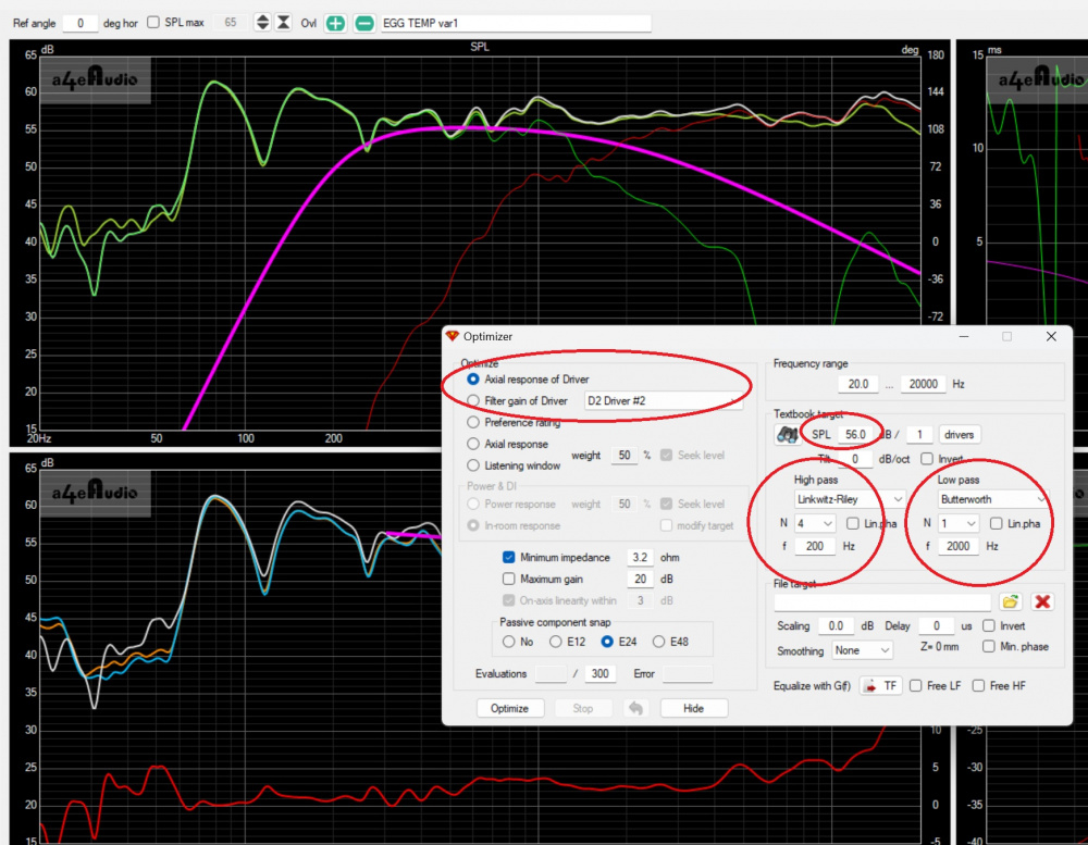
A lot of VituixCAD's functionality focuses on directivity issues, thus the whole Spinorama of measurements and downplays the traditional textbook crossovers named after people who solved equations decades ago. But you can still do all of that conventional stuff. In the screenshot below I have chosen a target to be the Axial response of Driver and selected Driver #2 (which is my woofer). You select your target SPL level, and whatever kind of slopes you desire (see the red circles), Linkwitz-Riley, Butterworth, Bessel, Chebyshev, Deuland, etc. (Even though there are not "technically" LR odd-order slopes, you can choose LR and N-order 3 to target what some people call LR3 slopes.) One of my few complaints of the program is that if I open the optimizer back up, it will revert to some other default and not the Axial response of Driver option, which I think is the authors way of trying to get me to focus on the other targets, but I could just be paranoid.
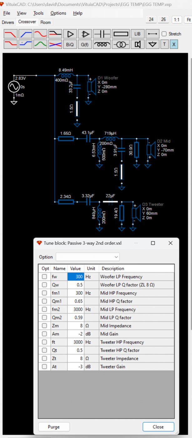
If I want to start off with a target LR2 crossover at 2khz but not sure what component values I need, I can go to the Library and load a 2nd order crossover (or a bunch of other options) with textbook components and start from there.
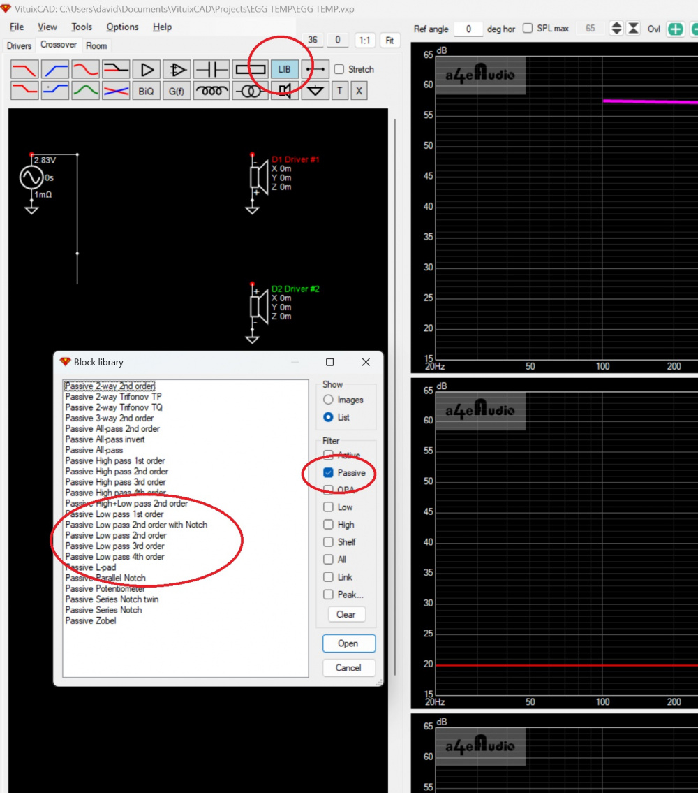
Here are the components and Tune Block for an LR2 passive 3-way...
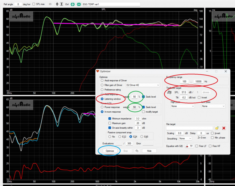
Moving away from the Axial response of drivers, you can set targets for Preference Rating, Axial Response or a weighted average of Listening Window (LW) and Power Response or In-room Response (IRR). Of course, I don't have to use the Optimizer, I can just set the targets and try to attain them myself.
Below I have set the Optimizer for 50% LW and 50% IRR. The blue "Seek level" box to the right of Listening Window is selected and I can choose the frequency range of the target, SPL level, and tilt in the options to the right.
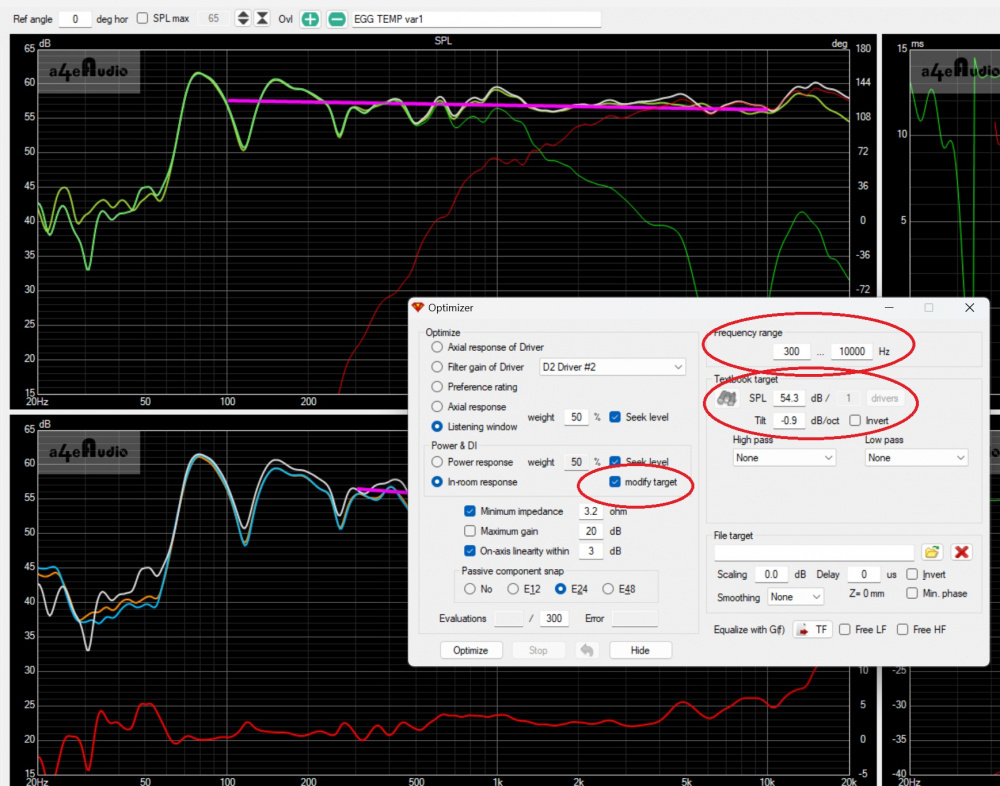
Because there is only one area to the right to display the target options, the default here is the Listening Window. To change the IRR target I have to select the "modify target" box (circled in red below) and the options to the right now reflect the IRR target options.
Of course, you don't have to do it all on your own. You can let VituixCAD do the work for you and select the Optimize button (circled in blue above in the Listening Window screenshot). This will run up to 300 iterations trying to get the best fit to your selected target options. If it isn't close enough after 300 iterations, just hit optimize again for another 300.
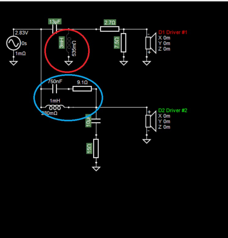
To run the optimizer, you have to select which components are "turned on" for the optimizer. For early prototyping you may just want them all to be turned on. Note, you don't have to use the directivity targets, if you want to target an LR2 High-pass of the tweeter, just put the appropriate components in place, turn them on for optimization and run optimize. Another possibility is you want to optimize 50% LW / 50% IRR but you KNOW where you need the Low-pass on the woofer to be. Here you can just turn those components "off" and optimize everything else.
In the screenshot below the components highlighted in green are turned on. However, the 3.0mh shunt inductor on the tweeter (red circle) has been set to "open" to force a first-order electrical filter on the tweeter. On the woofer, the inductor (and parallel capacitor-resistor) (all in the blue circle)have been turned "off" (and are not highlighted green) because I have determined that this provides the primary low-pass filter, as well as notch for cone breakup, that I want, and do not want to the optimizer to change them.


Comments
All news to me - thanks.
Lots of good info here. Thanks for sharing. I like your idea of loading the raw drivers into variants 6,7,& 8. It can be difficult to review (or recall) the original, unfiltered driver curves once a complicated crossover is in place.
One thing I find myself doing all the time is shutting off drivers for clarity. To do this, I open one of the driver icons and click the "O" button to shut it off (see woofer example below). In this way, the screen is cleared up and shows just one driver and xover section. With too much junk on the screen, it is extremely difficult to see just exactly what is causing a problem (big peak, narrow dip, low Z issue, phase alignment problem, breakup issue, etc.) If the problem goes away when you shut off a driver, then that driver and/or xover parts are the cause. Shutting off drivers is also a good way to run the optimizer, as you noted above, on just one section at a time.
Excellent little tutorial, David. Once I get the hang of this I am going to want to redo all the crossovers in every speaker that I have made.
I’m now also looking to do a re-run of my latest build per David’s excellent tips post. Maybe first just target the Xover range I’m looking for, and then keeping with a 2nd order LP and 3rd order HP (current build) and see what it optimizes for.
Should be interesting. (If I can teach this old dog a few new tricks).
I'm not a VituixCAD expert but I've designed 6 speakers in the last two years using it and have figured a lot of things out. Feel free as you proceed to ask questions here and we can add to the thread.
I got my tilt lines working, tweaked the values and tack soldered a crossover. It needs some further tweaking. The response was close, with a trough in the middle. Quite a few of the parts need to be very close in order to target specific areas. With 12 parts I'm gonna need more proto clips. I probably can eliminate the zobel on the woofer. Horizontal response sounds very good walking around. Vertical is kind of narrow, I suppose due to the shallow slopes. More chance for the drivers to interact with changes in time arrival. HP is at 1800 second order acoustic so I might be able to lower that just a bit without overdriving these tweeters.
This is very timely for me because as soon as I get some time I am going to start using this program instead of the other ones I have been using. Thanks Dave!
For those users of VituixCAD, Kimmo (the software's author) posted an article discussing interpretations of Spinorama and some different slope targets of Listening Window, Predicted In-room response, and Power Response. Because he doesn't show this link on his webpage I'm going to link the ASR post rather than direct linking the pdf file.
What room are they predicting? Asking for a friend.
I'm not sure your friend really wants to know, but...
The basis for the math of the Predicted In-Room Response is on pages 53-55 of the ANSI-CTA-2034-A document posted HERE. Basically like Sound Power calculations, but taking certain horizontal and vertical early reflections into account. I'm sure your friend agrees that considering Power Response is legitimate and doesn't only look at on-axis SPL. (In fact, I'm sure your friend agrees that considering off-axis response is also legitimate.)
Some of the points in Kimmo's article then is more relevant to your question. Once you have the Predicted In-Room Response (PIRR), which is just math, what do we do with it? Toole and Olive look at preference studies to determine a target slope to the PIRR curve. Kimmo's point is that depending on what kind of room you are in and your own listening preferences (or your target audience if designing for others) you can choose the appropriate target slope of the PIRR curve, say -0.5db per octave or -1.0 db per octave from 200Hz to 12khz. [So the answer to your question is YOU choose the target based on YOUR room, but the math of the PIRR curve is from the CTA standard based on Toole's work.] This isn't that different than targeting a small dip in the 1-4khz range of the on-axis SPL to take into account excess energy in the Power Response.
Cut and paste notwithstanding, you did not actually answer the question. Let's pretend for a minute that I might know a thing or two about sound reproduction and psychoacoustics myself - your entire post was pretty condescending and further...
Who's room? Mine? Yours? Some theoretical such as the "standard" implies?
Compromises, It seems better to try than to not
Beware placing too much faith in Amir. He is on record asking why speakers sound good when they do not "measure ideally" - see his review of CSS for example.
Sorry, but a couple things stick iny craw about the Klippel NFS and certain interpretations therein.
I have noticed instances where Amir says it's a resonance or a difficult capacitive speaker load, and totally called it what it wasn't, or gave an incorrect reasoning for the assumed result. However, call him out and get banned. I've seen that happen. From what I've heard about measurement details with the NFS and AP in relation Amir and Erin from Project Pad discussions with Lars and Andrew, there are yet some experiences to be learned.
InDIYana Event Website
You have clearly misread my post. I know what you were getting at, and I know you know "a thing or two". I just wasn't sure if it was a rhetorical question. In fact, that is why I mentioned off-axis and power response, because I know you know these things and don't need spinorama/VituixCAD to enlighten you. I wouldn't intentionally be condescending to you because you know a lot more than me about speaker building, so sorry if it came across the wrong way.
I place no faith in Amir and don't pay attention to what he says or really care about Klippel vs good DIY measurements with a mic. I do appreciate Kimmo's knowledge and opinions though. That article was (originally) a summary for Amir and Erin about how to present some of the Klippel results and Kimmo has made clear that raw measurements do not tell you everything about how a speaker sounds.
I had a number of problems using the alligator clip jumper wires - measurements would vary from day to day with the same crossover. So I started soldering my own clips with 18G wire, and often doubling up clips if possible to minimize resistance changes. YMMV.
Very true. I have also noticed this. I am now using Wago lever nuts. One wire per hole because if the wire diameters are slightly different the smaller one may not receive any clamping pressure. And I have also been tack soldering.
Yeah if you like soldering like I do I just do a half twist and solder all my proto x-os
I really enjoy soldering, so I tack solder all my prototype crossovers with maybe just one or two alligator clips for quickly swapping padding resistors. I made my own 18 awg soldered alligators.
This is my prototype xo for the omni woofers / OB mids project. I use a tiny dot of hot glue to stick the components to a piece of cardboard. Less likely to have a couple leads accidentally touch and damage my amp
My apologies for coming across harsh. I've had words with Amir in the past.
I've never looked into the Tools\Auxiliary section of VituixCAD before. Someone posted on another forum that they were measuring at 1.5 meters from the floor but only getting a reflection-free gating of 2 ms. Someone posted that they should be able to get closer to 6 ms and showed this simple calculator in the Tools\Auxiliary section. [Note: the screenshot below shows dimensions resulting in 4.65 ms, not the example of 1.5 m from floor]
My guess is that many people on MAC are already pretty familiar with the gating time for various distances from floor/ceiling, but this is kind of handy for me as I have a few alternate places to do measurements all with different ceiling heights.
However, the other tool I saw was the easy calculation of acoustic offset. I know WinPCD has a similar automated tool but I don't know about others software like Xsim. I use a dual-channel measurement system so don't need z-offset for crossover work, but I did create a 3D printed waveguide and I wanted the offset to match my exact tweeter and midwoofer. I didn't know about this tool and actually went back to the original PCD and Jeff's old paper on calculating the offset.
I was having trouble getting Vcad's time align tool to work properly for the longest time. Kept getting mismatch type timing errors. Then I discovered that I needed to uncheck the MP (minimum phase) button, because the frd's that I was using contained "as measured" phase data. Once I unchecked the MP buttons, it worked perfectly. And it is much faster than XSim's manual time alignment process.
I think linking to ASR is not a great idea. I often get drawn into stepping into sh$t when I'm over there.
We can link it directly to Kimmo's website:
https://kimmosaunisto.net/Misc/speaker_review_feedback.pdf
For the record, this is a document that summarizes some of weaknesses of the spinorama / CTA2034A, and gives feedback towards to how the measurements may be (mis)used by reviewers. The CTA2034A was based on research of last century- how the anechoic measurements from the NFS needs to be interpreted with caution, or how reviewers might want to use them as an adjunct to listening. For instance, the measurements are anechoic, and then you plonk it in some random/convenient area to in mono? And without discussion of acoustics of room, your listening pretences /biases (we all have them) or using graphs that are redundant.
I recently went on a deep dive of microphones (studio monitors). Turns out People are using all kinds of microphones that have all kind of frequency responses. . Fair enough they are content creators looking for equalization, and also can't afford the type of condensers that give a faithful 20-20KHz response ( without spending $$$$ to imitate their idols)
The circle of confusion will never end.
Embrace DIY- build for your ears, learn, share, & have fun.
^ Absolutely!
This hobby is for us individually - we just share our experiences so we feel less insane about our collective obsessions with it, IME/O.
Thanks for that ^ post, Thanh.
Enjoy guys.
RTFM and measurement guide for REW or ARTA, click all the buttons and see what they do.
Here's a quick tip, how to migrate from Xsim to VituixCAD:
That's it, enter crossover schematic from Xsim and same result will be presented in VituixCAD. Diffraction and merge tool can be used to create quasi-anechoic response without affecting mod-delay. No minimum phase BS required.
One of the things I like to do to improve my understanding of how crossovers and Vcad work is to simply load one of the various passive tuning blocks from Vcad's library onto the xover CAD screen. Then I connect the tuning block from the amplifier block to an empty driver icon that has no FRD or ZMA file attached to it. Vcad defaults to a flat FRD response and a flat ZMA impedance (8 ohms) when you fail to load real curves to the driver icons. Then I play around with the tuning block settings to see how different settings and component values affect the on axis response, filter response, impedance and group delay. This has really helped me to expand my knowledge of how to properly pound all the squiggles flat when I am working on a real xover.
And you can still go into the driver window and change the impedance to 4 and it will just default to a flat 4 ohms.
Here is a tip for using a VituixCAD feature that I was not aware of until I accidently stumbled onto it yesterday. I have all the polar data loaded into VituixCAD for my current build, but then I decided that I needed to change the design axis from 0 degrees on tweeter axis to 20 degrees off tweeter axis (each speaker pointing straight forward into the listening room instead of toed-in toward the listener). Clicking around, I discovered that all I have to do is change the reference angle to 20 degrees. This will make the curves magically transition over to the new design axis. See red circles below. As you can see, this makes a huge difference in the squgglies. Basically what I am doing is allowing the tweeter to peak up a few dB on axis so that I can achieve a better looking power response curve.
Reference angle set to 0 degrees horizontal, which results in a peaky looking response above 10kHz:
Reference angle set to 20 degrees horizontal, which results in a flat looking response above 10kHz: