Site Links
Howdy, Stranger!
It looks like you're new here. If you want to get involved, click one of these buttons!
Quick Links
Categories
In this Discussion
Who's Online (0)
Radiusaurus Revival

I'm suffering from a mild case of speaker building burnout. So this year, instead of scratch building yet another loudspeaker, I decided to convert and merge two previously completed speaker projects. The idea here is to take the best aspects of each one and create a new and hopefully better sounding speaker.
The two projects that I will be merging are as follows. I selected these because they seemed to excel at different ends of the audio spectrum.
1) Neo-Deepo: A two way using a B/G Neo-8 crossed at 700Hz to two TB 1139SIFs in a 2 cu ft box. Tuning was approx 28 Hz. These played at InDIYana 2014 (see pics). They had great bass, digging deep to 25Hz, but the design was a "fail" because the 1139's roll off too fast. This created a "hole" or FR dip in the 300 to 1kHz region that I could not solve by applying standard BSC correction techniques.
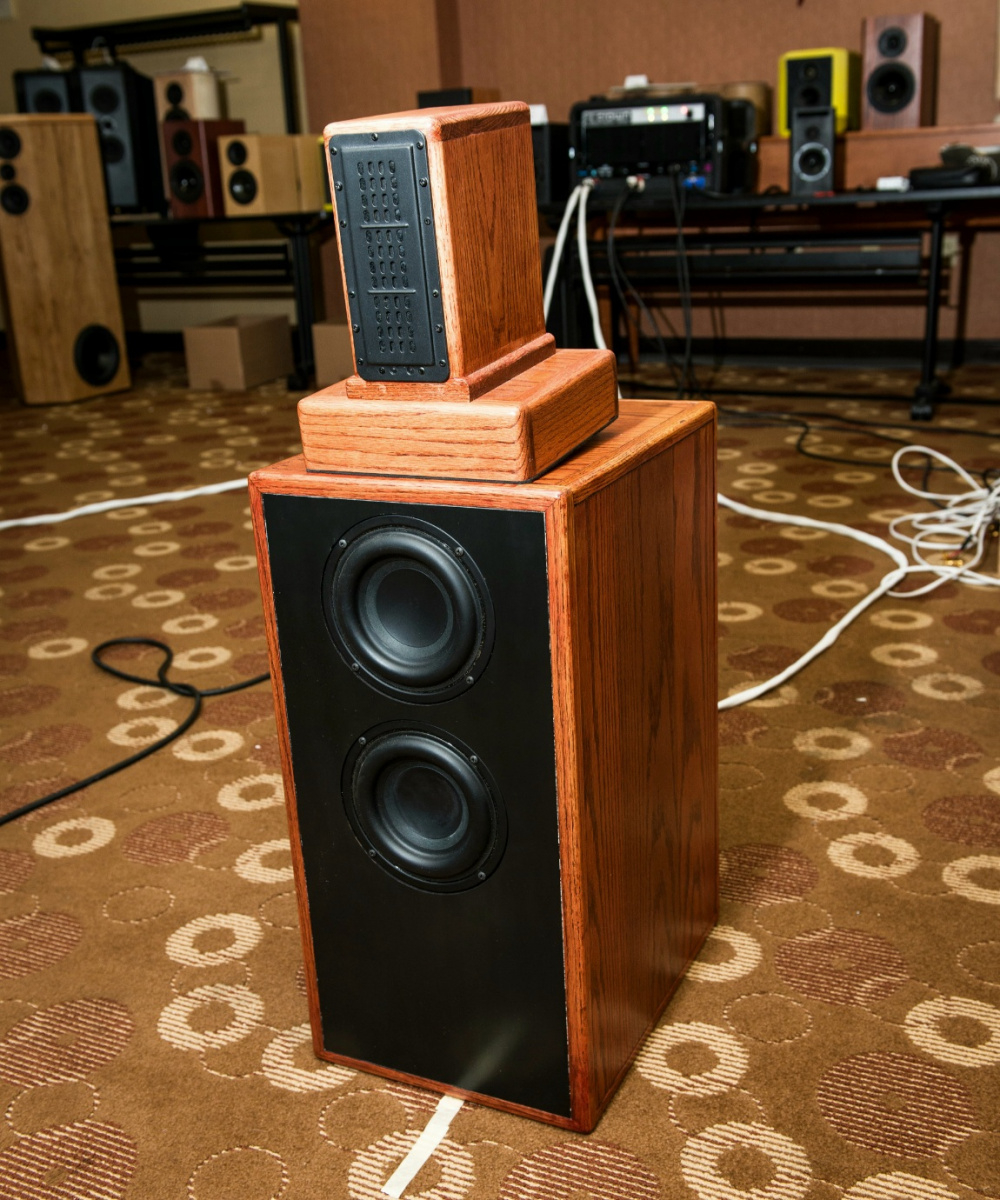
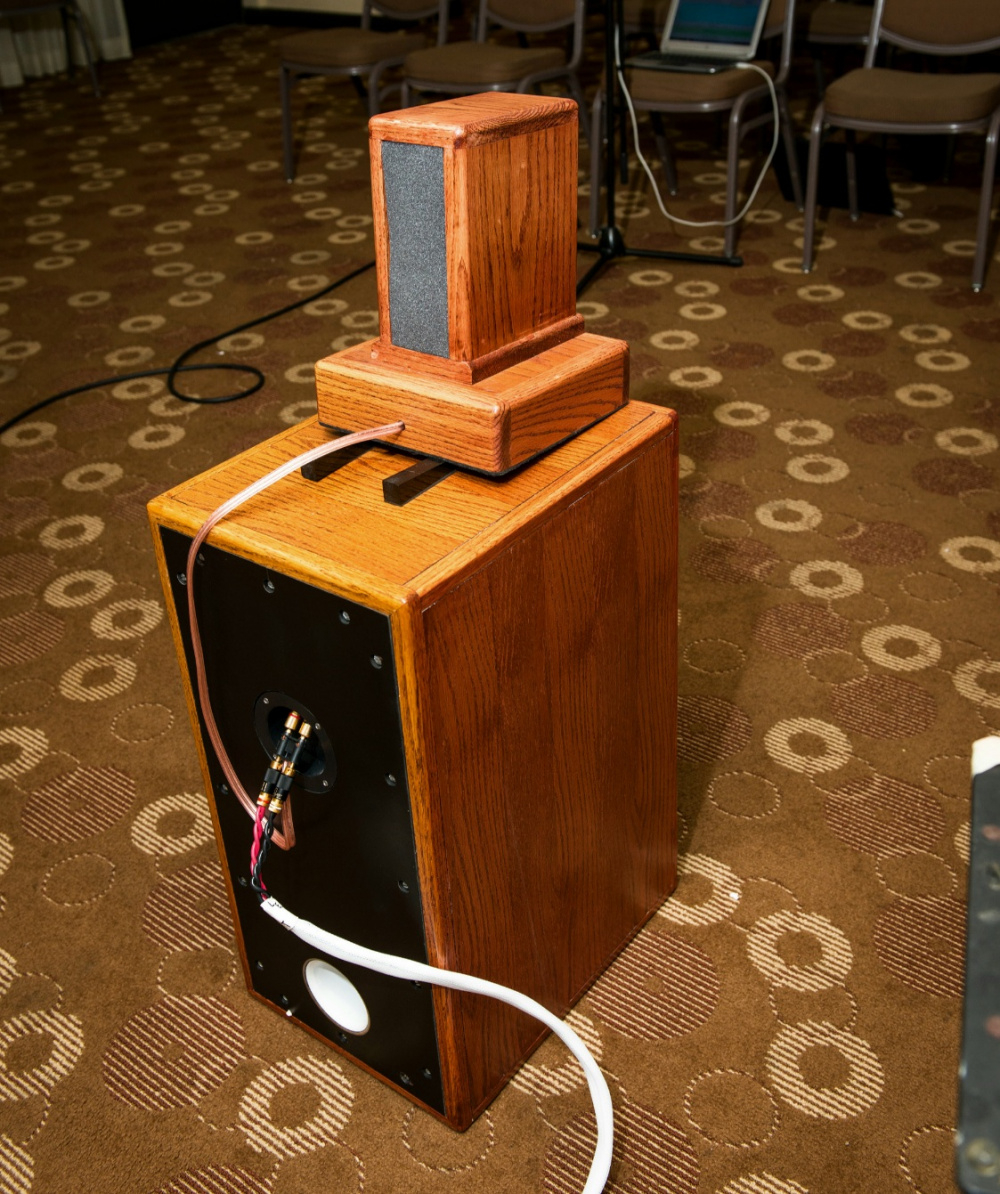
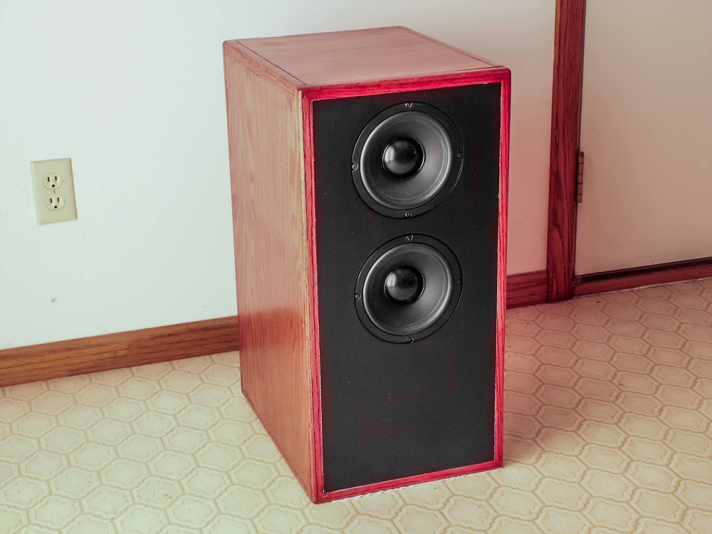
2) Radiusaurus: I took these to InDIYana 2021 as my open back entry (see pics). They sounded kind of lean in the deep bass area and the open back tweeter sounded kind of phasy and out of place when crossed to the bass reflex ND-90's.
Plan: Create a two cabinet "hybrid" active/passive speaker. The lower cabinet will use the pair of TB SIF1139's in the existing 2 cu ft boxes, connected to a pair of Dayton SPA250 plate amps. Crossover will be somewhere in the 40 to 200Hz range using the plate amps 4th order low pass filter.
The upper cabinet will be the existing Radiusaurus cabinet with the Neo-3 and four ND-90's passively crossed at about 2.5kHz. I'll be converting the Neo-3 back to a sealed back chamber. Then I'll modify the upper xover based on testing/listening. For the lower xover on the ND-90s, I'll be running them open on the bottom and changing the loading format from bass reflex to either sealed or aperiodic, based on listening tests. The challenge will be to get the ND-90's to blend well with the 1139's. The 1139's will be driven by the plate amps set to a very low xover point.
I'll stop back and post pics as I go along.


Comments
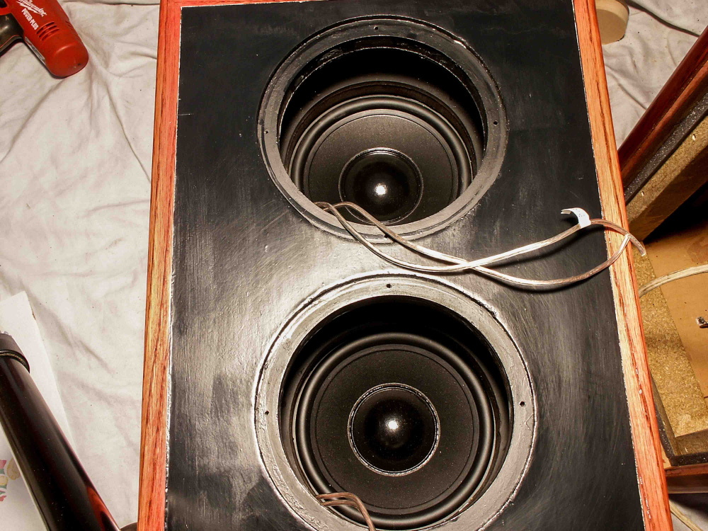
Re-furbing of the woofer cabs is underway. The backs are removable, which makes things nice for retro fitting operations. I removed the drivers and two 700Hz xover boards. Then I re-lined both cabs with 1/2" thick fiberglass from Menards. I used the Armstrong Pebble 2x4 stuff they sell as ceiling tiles. I did have some pink fiberglass batts that I installed previously for damping, but it was poorly installed and falling apart.
The cabs are 10.5 x 23 x 14.5" internally (2 cu ft). The walls are 1 inch thick (3/4" MDF + 1/4 oak veneer plywood). The cabs were originally built with isobarik tunnels, which have now been re-purposed to non-isobarik by removing the internal woofer baffles. As a result, the structure around the woofer mounting holes is very thick and rigid. The ports are 3" ID by 12" long and use a 90 degree PVC elbow. I integrated the ports onto the rear panel with a small MDF mounting board and gave them 3/8" roundovers inside and out. I think I might increase the external roundover to 3/4" radius, but the internal one has to remain at 3/8" I have no way of getting my router in there to re-do it.
All I have to do at this point is install the drivers and run wires to the input cup. No plate amp cutout. The amp will simply sit on the floor behind the cabinet.
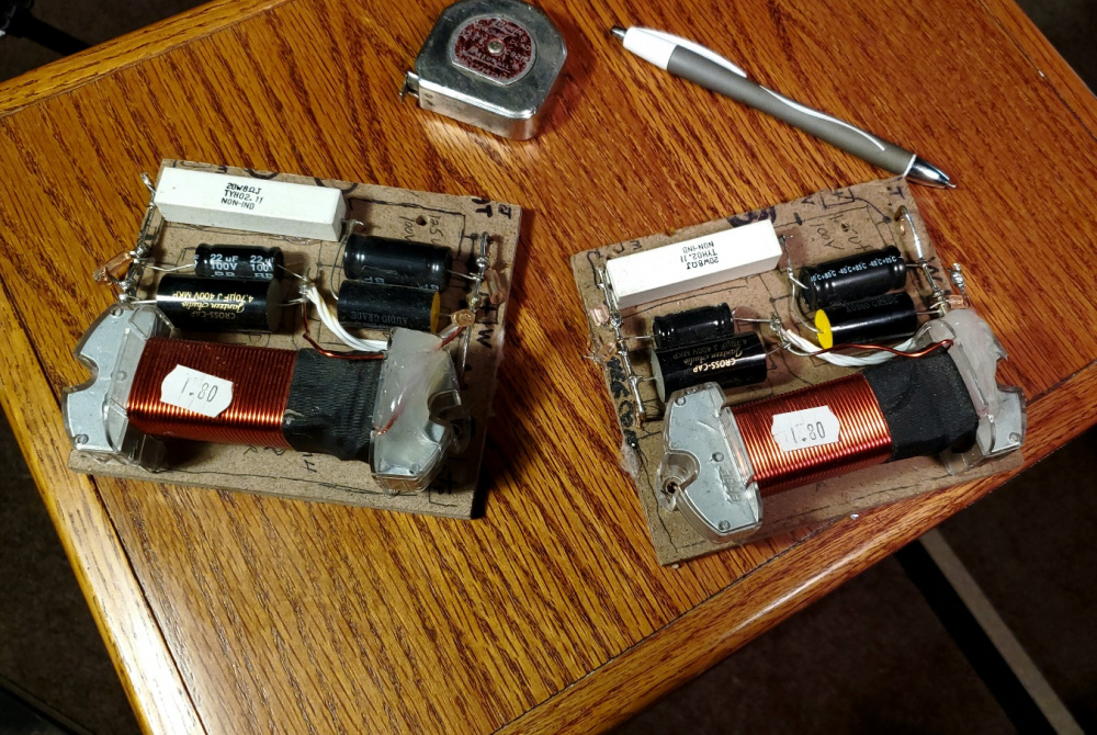
Removed 700Hz xover boards. They will go in my junk parts box:
Removable back panels. They are 1 inch think (3/4" MDF + 1/4" masonite):
Sturdy little buggers! So there wasn't any woofers inside to begin with? Possible after thought if it needed to be?
Reviving and updating older projects is a great idea, it saves a lot of time, money, and landfill space!
I agree. Repurposing enclosures can mean only a new removable baffle needs to be made.
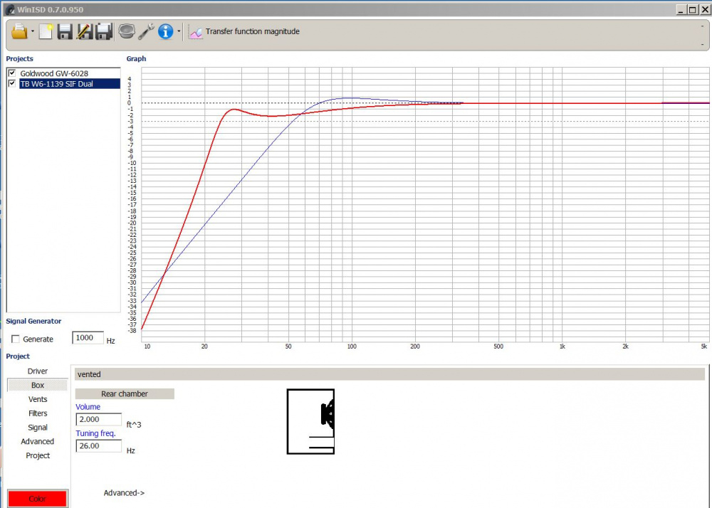
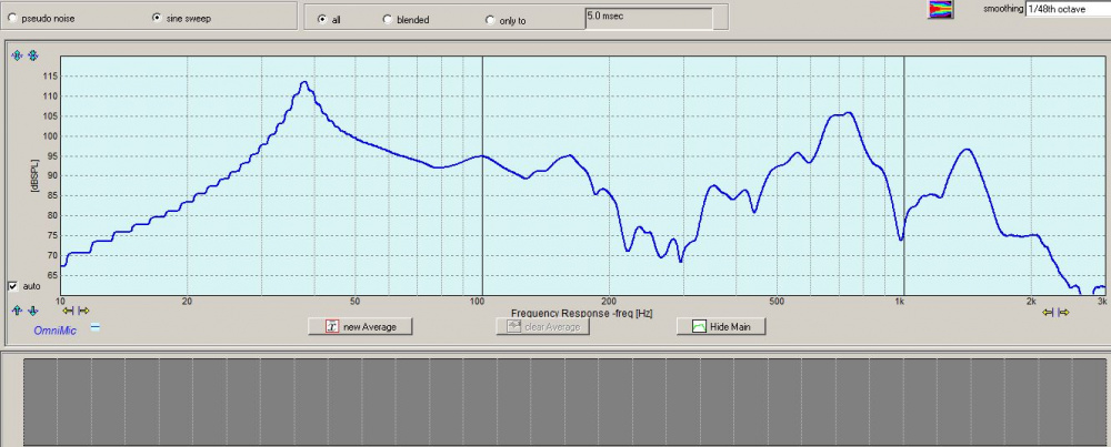
Yes, the original design had dual isobarik woofers mounted internally and a total of 4 woofers per cab. I forgot to mention the original design in my write up (this is now the 3rd revision of the cab). Initially, back in 2003, I built the cabs to house 2 pairs of Goldwood GW-6028 6.5" woofers in an isobarik configuration. It was sealed with no port. It played loud, but had no deep bass at all (see graph below). So, in 2013 I replaced the 4 Goldwood woofers with two TB-W6-1139SIF's and eliminated the isobarik tunnels by partially removing the inner baffle board with a hand drill. Today, I modified the cabs once again by completely removing the inner baffle board with a sawzall, replacing the fiberglass, and removing the xover board. I found a few pics of the original cab from 2003 and have attached them below. Also put together a WinISD comparison of the two alignments. This makes a huge difference in deep bass output.
WinISD comparison:
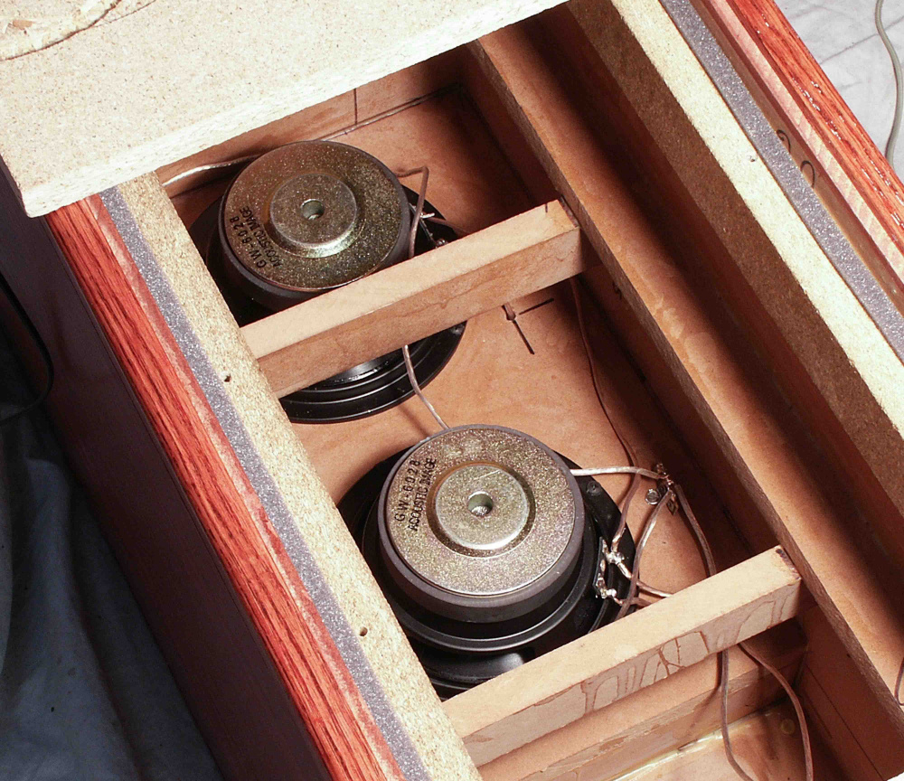
Original internal Goldwood woofers, viewed from the inside:
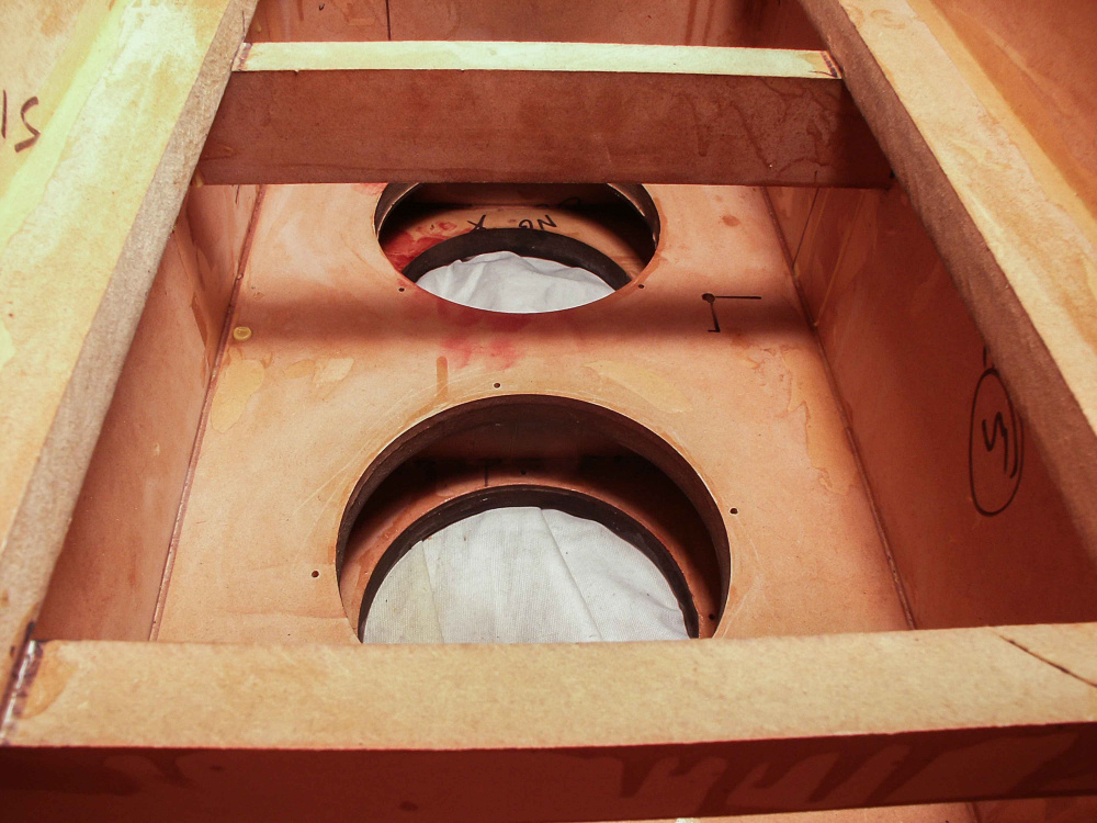
Original internal baffle boards and tunnels:
Original internal Goldwood woofers, viewed from the outside:
Original cab with quad set of Goldwood woofers installed:
All wired up and ready to reinstall the backs.
After buttoning it up, I measured and merged NF cone + NF port, as a sanity check, to make sure I didn't create any air leaks around the driver flanges or rear panel gasket during re-assembly. Looks good to me. Both speakers measure the same. I had the SPA-250 plate amp set to 110Hz for the test. Later on, I can adjust this xover point up and down from 40Hz to 180Hz as needed. Basically, they measure flat to 26Hz with an F3/6/10 of 24/23/21.
Now that the lower woofer section is done, I can turn my attention to the upper mid/tweeter section. The first order of business will be to glue the plastic triagular cups back onto the backs of the Neo3 tweeters. These cups are lined internally with several slices of some very soft, fluffy type felt material. I thoroughy cleaned off the old crusty glue along the cup's perimeter. I'll be gluing them on shortly with a very thin bead of silicone rubber cement and letting them cure overnight. I'll use Just enough silicone to give the cups a good seal and keep them from vibrating loose.
You might want to consider something other than silicone. Silicone off gasses can deteriate other glues.
I'll second what Ken said.
water based adhesive caulk works pretty good - silicone detoriate my sense of smell too
I knew you guys were going to say that. But I did it anyhow. This is the second time that I have glued these cups back on using silicone. It did not seem to cause a problem the last time I did it, but time will tell. I used a very small bead and as I was applying it, I biased the bead toward the outer edge of the seam so that when I pressed the cup in place, most of the excess silicone squeezed to the outside and not the inside of the cup. This will hopefully reduce the concentration of gases trapped under the cup.
Anarchist
I put the tweeter back in the cabinet today and did an OmniMic measurement with the original crossover. I wanted to compare a new measurement to the one I took 4 years ago. I tried as best I could to measure them in the exact spot, mic position, gating, etc., as before. The two curves, offset by 10db for clarify, look pretty much the same as before, so the tweeters should still be OK.
Try this measurement again after a few hours of play time and I suspect it will smooth-out/flatten a bit - looks fine to me, as is; except for that peak at 3KHz - but my ears are different than yours, Bill.
Ya, that bump at 3kHz is somewhat concerning. I could just leave the passive xovers the same and experiment with blending the subwoofers into the mix at around 100Hz or so. But since I have plenty of time between now and the Speaker Design Competition (SDC), I think I will run up a new set of measurements and take a fresh look at the xovers in VituixCAD. The current xovers were designed using OmniMic and XSim.
If I go this route, I'll have to decide how I want to go about it, as measuring an MMTMM is not a simple task. Below is the baffle layout drawing. Since I think I can easily flip and clamp the entire cabinet in either a horizontal or vertical position on my rotating DIY polar table, I may attempt to capture both horizontal and vertical spins and see how that goes. I can then keep the microphone in the same on-tweeter axis position for all measurements. The four ND90's are connected in series/parallel, so I would measure them as a single driver on axis with the tweeter. Kind of like measuring a single, tall, coaxial type driver that has a Neo3 tweeter in the middle of it.
Ooh! - I got chills when you said something about a coaxial with a ribbon in the center!
Is it the ND90 or the Neo3 causing the 3K bump? I'd wager a guess that it goes away off axis.
It is the Neo3 causing the glitch. Since I still have the speaker mounted on my polar table, I took three new measurements and loaded them into OmniMic for comparison (see below). The glitch does not go away off axis. To make these measurements, I replaced the tweeter and woofer connections to the xover with jumpers so that I can measure the tweeter or woofers alone with or without their respective crossover sections installed. The current schematic is also attached. Looks like I have some work to do. A half wavelength at 3kHz is 2.2 inches, which just happens to be the distance between the tweeter top (or bottom) row of slots and the rubber surround of the ND-90 woofers.
Has this been done? Not a coaxial as such from a technical standpoint, but a DIY concentric driver made by placing a ribbon driver in the center and then mounting 6 or 8 small 2.5" or 3" midrange or midbass drivers around the tweeter to form a circle.
Yes, some studio monitors are this way. Elac has a few too.
DIY drivers? Nope.
InDIYana Event Website
Tom, I got to thinking again about your comment and decided to test the tweeter again, this time comparing on-axis to 15 degrees VERTICAL off axis. My previous test only compared on-axis to 30 degrees HORIZONTAL off axis and the 3k bump did not go away. But when I raise the mic by 15 degrees, it goes away completely. So your guess was correct. This test also confirms that it is the two nearby ND90 rubber surrounds (both the upper and lower surrounds acting together) that is actually causing the on-axis glitch.
Well at least it's very narrow and only 2.5 dB. Might not be overly offensive.
Since I will be crossing the ND90's to the 1139 sub cabs at about 100Hz, I decided to convert the ND90 cabs from a bass reflex alignment over to a sealed box type alignment.
For reference, here is a drawing of the original cabs:
I removed the backs and stuffed the upper and lower sections with poly fil. I also pushed a little poly-fil into the port to prevent resonance.
Before re-installing the backs, I pushed a foam plug into each port to seal it off.
The NF port measurement for the original ND90 cabs looked horrible, with lots of peaks and dips in the 150Hz to 1.5kHz range. Sealing it up and stuffing the cabs fixes the problem.
The sealed cabs have a lower Fc (101Hz vs 105Hz) and a lower Qtc of .84. The impedance curve is now smoother and the glitches in the 200 to 300Hz region are gone.
Have not listened to them yet, but I am getting close.
Very nice, I am surprised by such a low crossover point, woofers to mids.
Thanks. 100Hz seems low, but I think it is the logical spot in this particular case. In a sealed, 1cu.ft. box, the quad set of ND90's have a natural roll off of 12dB/octave at 100Hz. In addition, four drivers have an equivalent cone area of 7" , so they can handle the power down low. The TB W6-1139's, on the other hand, start to roll off above 100Hz due to VC inductance and cone mass. I tried moving the xover lower (60-80Hz or so) but the VituixCAD model started to show a dip in the 80-90Hz response. I tried moving the xover higher (150-200Hz) but the model showed either a big peak (in phase connection) or a big dip (180 degree out of phase connection). The best model was at 100Hz.
WinISD model of quad set of ND90's in 1cuft sealed box:
TB NF cone + Port measurement. Note the response roll off above 100Hz:
I abandoned the above xover revision in favor of a much easier mod that sounds and measures much better. It uses the same trick that EQ used for the "Missing Link" competition (InDIYana 2022). I've been listening to the mod for a while now and it really improves the sound of the Neo3 tweeter. I'll post the revised schematic and measurements tomorrow.
Here is my revised (and final) 6 pack model. This one is going to the SDC next month. It checks all the boxes. Measures and sounds good too. And this revision only involves replacing or adding a total of 4 parts to the original xover, which is nice on the pocketbook. I'm using a two part notch filter on the Neo3 to create a custom "BBC style dip" correction curve to balance the on and off axis response curves. It peaks up just a tad on-axis above 10kHz, but the dual filters result in relatively smooth and downward sloping Power Response and PIR curves. And it gets a very high preference rating score using the default set of equations. I currently have the revision clipped in place temporarily with jumpers, so now it is time to pull the xovers out and wire it up permanently. After this is done, all I will have left to do is to fabricate a small box to house the external SPA-250 plate amps. Thinking of making a nice cherry or walnut box, but I'll probably cheap out and use Menard's laminated shelving panels.
Friday night open unlimited? Hope you have got the interface figured out.