Site Links
Howdy, Stranger!
It looks like you're new here. If you want to get involved, click one of these buttons!
Quick Links
Categories
In this Discussion
Who's Online (0)
Enclosure Tuning - Measurements Make No Sense

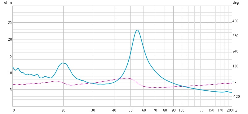
These measurements make no sense to me. Based on the impedance, I'm tuned to the mid-30s. Based on the nearfield measurements, I'm tuned to 22hz. What the actual fuck. Make it make sense.
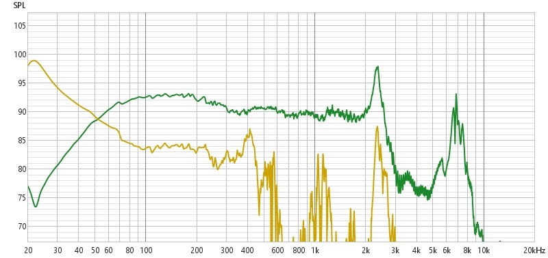
Drivers are dual HiVi M8N wired in parallel. I measured one mid nearfield, both with a blanket over the second mid and without. Measurements in the image are with the second mid covered. Port is on the baffle below the midbass. I measured the driver nearest the port.
Enclosure is 83L. Port is 4" diameter and length is 9.625". I was aiming for a tuning around 30hz, but wasn't concerned with a 31-32hz tuning. WinISD said I needed a port 9.875", Unibox said 9.25" so I split the difference. Enclosure is internally 14" deep, port extends 9.375" into the enclosure. Walls are lined with 1" open cell foam the top ~ 12" are heavily stuffed with fill, as is the bottom 7" where the port is except for near the port exit. I kept the walls and area near the port exit clear of both fill and lining.
To have tuning of 22hz I'd need an effective port length of 20". Because the impedance graph is close I'd say this is some sort of error in my nearfield measurements, but both the port and driver measurements correlate. My old PC took a crap so this is my first time measuring with my new to me PC. It's possible I have a setting or something off that would affect the measurements but I have no idea what would give this kind of result.
Comments
Dude, no offense. You had a good analysis.
But I'm pretty sure that the impedance sweep for a BR box shows Fb tuning at the Z min between the 2 peaks.
If you measure nearfield port, that should have a maximum output around the designed Fb, and the woofer will have a big dip at Fb.
Eyeballing the impedance, I'd say Fb is around 35 HZ .
Also, you might want to check the box for leaks. The peaks should be a bit sharper.
Hope this helps!
That's my question here. The port and driver NF shows 22hz tuning but the impedance shows mid-30s.
>
This
Can you calibrate your Limp to verify it is working right? After I got a new laptop late last year, I had to recalibrate my impedance rig too.
I still don't know the reason, but it seems nearfield FR of port and driver vs impedance always gives me 3 different values. They are usually not 12 Hz different though.
I think John and Don are likely at least partially correct. Unless the woofer is that well damped on its own (doubtful), it should have a higher magnitude at resonance. Seeing how low in magnitude the lower peak is looks more like; a TL alignment, an aperiodically damped vented alignment, a leak, a tuning that is too low, or a woofer that had a higher than spec Fs.
I would check for leaks first, and recalibrate Limp if you can. Check woofer to verify which is closer- FR or Z. If FR could be off, check cal there too, or check Windows settings.
InDIYana Event Website
The impedance peaks are definitely not symmetrical and seem to far apart.
Remove the port and remeasure the NFs and see if they still correlate.
Remeasured with a DATS v2 and got a much better looking measurement that, unfortunately, shows I'm tuned too low Based on this I'm tuned to around 27hz, which is much closer to the 22hz measured by REW. So now I have to figure out how to shorten a PVC port tube within a constructed enclosure....yay!
The peaks also look better, although part of the issue on the prior measurement was scale...I had zoomed in the frequency axis, which is going to dull the peaks.
This is a different speaker that Ben measured with his WT3. I did this as a sanity check to see which was correct; the DATS or Limp. The blue is Ben's WT3, the purple is the DATS, and the gold is the Limp measurements. You can see below 200hz they deviate with the Limp showing a higher tuning than both of the other measurement methods even though the peaks are at the same frequency. The shape of the dip between the peaks is different.
If you figure out a good way to do this, please post it.
Just make it a touch smaller diameter. Stuff it with drinking straws, for example.
Here is what I would do....
Cut a hole in the bottom with a hole saw. Make the hole close to the end so that you can use a jig saw through the hole to shorten the port. Usually, the serrated Bosch jig saw bits are long enough for this task. Remove a half inch. You may have to Dremel cut off the other side. Plug bottom hole with tape around removed bottom plug or PVC cap and remeasure. Repeat if necessary.
Add hardboard bottom panel over adhesive patched hole.
Edit: one of the oscillating cutter head tools could also work.
InDIYana Event Website
Home depot sells a PVC cutting "tool" which is basically just a metal cable with handles. Wrap it around the PVC and "saw" with the cable until you're through the PVC. With an 8" hole right above the port, I think I may be able to make that work.
Also a 4" port is big enough to get my hand in. Might try a dremel with a cutoff wheel from the inside of the port. The cut will not be very smooth, however.
My last resort will be on par with Ben's suggestion. Just cut the bottom off, sawzall the port to length and either patch the hole or just attach a whole new bottom panel. This may not be terrible as I can oversize it a bit, add some roundovers and make it look like a base. Tweeter level will be half to three quarter of an inch higher than originally planned. Just going to have to tell my daughter and son in law to sit up a little straighter for best results, LOL
A die grinder or even a dremel with a thin cut off wheel. Shouldn't be a big deal.
I used a dremel with a small round blade. Be careful and cut less than you’d think, and measure.
dremel with a cutoff wheel, or a mini-hacksaw.
Standard cutoff wheel for the dremel would be a nightmare since they are so delicate. The fiber reinforced might work a little better. But I recommend the Dremel #543 (or similar off brand part).
I think I have a circular saw blade for it that is solid metal that I used to use on fiberglass for car audio. If not I'll look into that wheel.
I just saw this thread and was going post about throwing a blanket over one woofer that shares the same air space as the one which had a near field FR taken. That measurement below 100 Hz is not valid IMHO
The big reinforced Dremel cutting wheels are about 1.5" in diameter, and come in the convenient twist-lock mandrel style. I've used them on many things.
There is a small circular saw attachment that I have used for plastics.
However, the right angle oscillating head cutter would take less time, have less chance of throwing the tool and provoking injury, and likely be a more accurate cut. Also, this tool may actually fit in the cabinet and allow fixing without altering the cabinet.
InDIYana Event Website
Got a link Ben? I couldn't find what you're referring to for a right angle oscillating head cutter.
The FR had the blanket over the 2nd woofer. But honestly the difference was negligible, especially down this low. There was a very slight elevation in the upper frequencies without the blanket
https://www.homedepot.com/p/RIDGID-4-Amp-Corded-Oscillating-Multi-Tool-R28700/316341817?g_store=2024&source=shoppingads&locale=en-US&pla&utm_source=google&utm_medium=vantage&utm_campaign=23680&utm_content=25333&mtc=SHOPPING-RM-RMP-GGL-D25P-Multi-NA-RIDGID-NA-PMAX-NA-NA-MK862179001-23680-NBR-7-NA-VNT-FY24Q1_Q4_RIDGID_D25P_RM__AON_CPT&cm_mmc=SHOPPING-RM-RMP-GGL-D25P-Multi-NA-RIDGID-NA-PMAX-NA-NA-MK862179001-23680-NBR-7-NA-VNT-FY24Q1_Q4_RIDGID_D25P_RM__AON_CPT-71700000117447636--&gad_source=1&gclid=CjwKCAjwpbi4BhByEiwAMC8JndVi1pv8s-dzB0r9dulX_3-BrMgr1WHNQpxJ0zFG12Ma1-m1-2BN-RoCf60QAvD_BwE&gclsrc=aw.ds
InDIYana Event Website
I bought the Makita version that uses my drill batteries a few years ago. What a handy freaking tool!
I imagine the battery version can get in almost any nook you need to access too. The cutter being at different angles is slick...
InDIYana Event Website
Ah yeah I have the Harbor Freight version, because I'm cheap . There is a window brace right above the port limiting my access from above. I may not be able to get a good angle on the port from inside the cab.
You can angle the end of the port too if needed, as it works like a flare.
InDIYana Event Website
You know what, somebody sells the survival tool of a wire with finger loops and abrasive that can cut a tree limb.
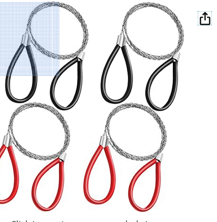
Should work even with a brace.
https://a.co/d/6TiV9vi
Well, after hours testing different methods to figure out the best way to shorten the port, and hours more with a dremel and cut off wheel, and more than half a dozen cuts and dozens of measurements... I finally got there. I started at a 9.625" port, which ALL the calculators said should be close. Ended up at 4.5" for a tune right at 30hz based on driver nearfield measurements. I'm reasonably happy with the results thankfully, at least on paper.
Summed response, where I started vs ended, level matched based on the peak @ 2.3khz
Final individual nearfield measurements for port and woofer
Final Impedance
Results (blue) look very solid !
I ended up (on one of my projects) putting a sock lightly stuffed in the port - who knew?
Thanks! These are going to my daughter so I didn't want to do anything that made them seem sort of rigged to make them work.
I was pretty nervous to cut the second enclosure port in case the measurements ended up wildly different for some unforeseen reason, or that I was going to screw up the cut. But luckily from 200hz down, the important part for these measurements, they match damn near perfect.
Fix one problem, another appears
Quality control on the Q1R is horrendous, apparently. One has no ferrofluid (red), one has the correct amount of ferrofluid (gold), one has way too much ferrofluid or some other problem (teal). The teal was the replacement they sent me under warranty to replace the red no ferrfluid driver.
The no ferrofluid has a huge peak before rolloff, however distortion measures significantly better. I know HiFiCompass recommends eliminating the ferrofluid. I didn't want to go that route, but may end up there.
You can order FF from PE too. However, I would wager that they should be lower HD without, even if lower power handling is a secondary disadvantage.
InDIYana Event Website