Site Links
Howdy, Stranger!
It looks like you're new here. If you want to get involved, click one of these buttons!
Quick Links
Categories
Who's Online (0)
Let's Build A Digital Preamplifier! (Arduino/PGA2311)
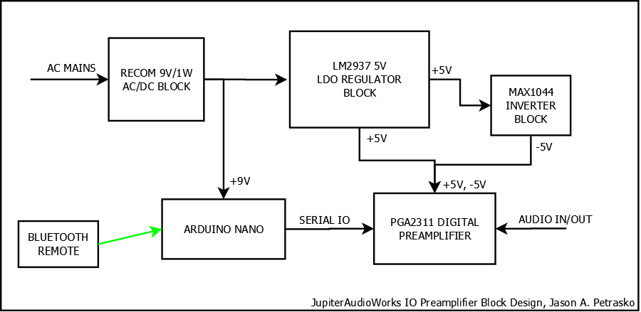
So I am going to record and discuss my progress designing and building a digital stereo preamplifier here. I am no electrical engineer, so I'm going to be using a lot of reference circuits. Commentary is welcome though. I have high confidence in this design quality, as I have seen many DIY efforts to do just this and resulting praise in the overall performance. Here is the block diagram of my plan:

As you can see I'm using a commercial 1 watt AC/DC switching power supply as the core. Its a quality part that is pretty cheap (12$ at mouser). That will supply 9V DC to the Arduino controller and then pass 9V to the LM2937 regulator. That regulator block creates a clean 5V DC to drive the PGA2311. I still need -5V for it though, and that is achieved through a MAX1044 switching inverter. The MAX1044 is a cheap effective solution because it can be "boosted" to push its switching freq. above 30khz and outside the audible range.
The reference circuits I'll be using are simple enough to implement on point to point perfboard, and I'll be doing that for the final prototype (the one that will be in the revised Jupiter Station). For now though I have enough breadboards to work it all up with a mess of jumpers! I'll start with the power supplies, as I can't get it working at all until I get that in order. I'll be adding reference schematics for each block here as I progress. Let's start with the simplest:

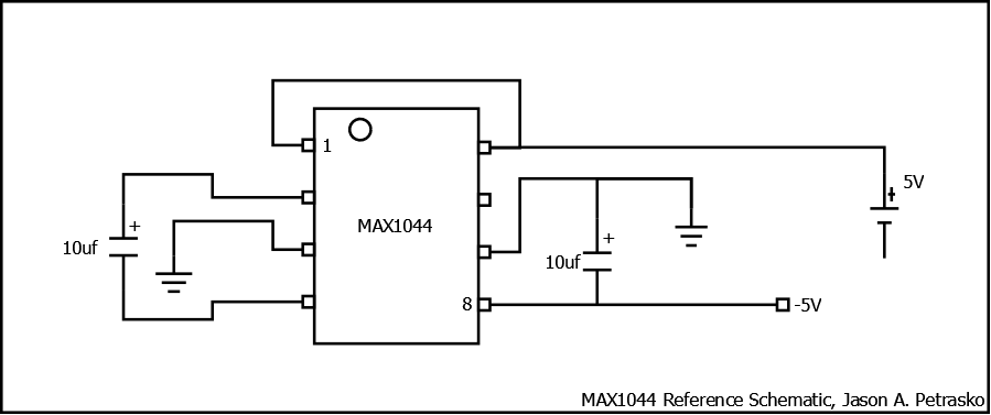
Here is the MAX1044 in PDIP-8 form, using the most minimal of configurations. Pin 1 is driven high to boost the switching freq. and Pin 6 is N/C because it is for an external oscillator. So that's it, 2 caps and some wiring gets you an inverted DC voltage
More to come!

As you can see I'm using a commercial 1 watt AC/DC switching power supply as the core. Its a quality part that is pretty cheap (12$ at mouser). That will supply 9V DC to the Arduino controller and then pass 9V to the LM2937 regulator. That regulator block creates a clean 5V DC to drive the PGA2311. I still need -5V for it though, and that is achieved through a MAX1044 switching inverter. The MAX1044 is a cheap effective solution because it can be "boosted" to push its switching freq. above 30khz and outside the audible range.
The reference circuits I'll be using are simple enough to implement on point to point perfboard, and I'll be doing that for the final prototype (the one that will be in the revised Jupiter Station). For now though I have enough breadboards to work it all up with a mess of jumpers! I'll start with the power supplies, as I can't get it working at all until I get that in order. I'll be adding reference schematics for each block here as I progress. Let's start with the simplest:

Here is the MAX1044 in PDIP-8 form, using the most minimal of configurations. Pin 1 is driven high to boost the switching freq. and Pin 6 is N/C because it is for an external oscillator. So that's it, 2 caps and some wiring gets you an inverted DC voltage
More to come!
= Howard Stark: "This is the key to the future. I'm limited by the technology of my time, but one day you'll figure this out."

Comments
Assembled on the breadboard and tested:
Its a pretty small simple circuit, should be easy to transfer to the perf board and solder up in a timely fashion. The RECOM AC/DC is the monolithic block at the top. All the power block parts are on the breadboard at left.
Now I can handle the PGA2311 circuit, and begin testing the preamp itself!