Site Links
Howdy, Stranger!
It looks like you're new here. If you want to get involved, click one of these buttons!
Quick Links
Categories
Who's Online (0)
slot-loaded tweeters (and 2 much time on my hands...)

With claims of 140 x 40 dispersion (i.e. the Beyma ‘s), would appear to be a good way to minimize ceiling/floor reflections and at the same time broaden the listening sweet spot. (If interested in the theory behind diffraction- it’s a bit long; https://www.youtube.com/watch?v=DU3I-h8nyhE )
So it got me thinking, could this be incorporated into a coaxial?
Selected a DaytonAudio 4in (not my fav coax, but priced for destruction…). First thought- good project for a 3D printer, but unfortunately last time I looked- not in my toolbox. So what can I come up with that can be trimmed to fit, with a needed dome to mirror the tweeter? And further needed to raise approx 1/32 off the center flange to provide clearance. Came up with using a ping-pong ball, and of all things trimmed off a ring from a chair leg floor protector I had (surprisingly an exact fit 7/8th inch ring). As for the ping-pong ball, cuts easily, sanded to size (sanded against fine grain sheet flat on a table top), and glued to the trim ring, and then the tweeter flange. Also put a little glue to underneath side as an attempt to dampen the ping-pong ball a bit.
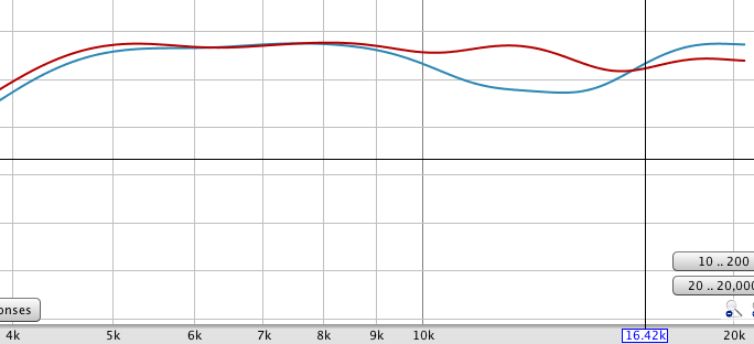
I’ve attached a few pics of the process, and a couple of frequency charts. The first frequency chart is of the tweeter ‘as was’ - actually kind of ugly off axis (approx 15-20 degrees off axis). The second is with the ping-pong ball slot in place. While it does seem to help on a relative basis on one axis, measuring from the other axis rolls off the response (hoped for, expected, and a good thing) but does so in a roller-coaster response (not so good). But heck, it’s a ping-pong ball.


Comments
Cool experiment!