Site Links
Howdy, Stranger!
It looks like you're new here. If you want to get involved, click one of these buttons!
Quick Links
Categories
In this Discussion
Who's Online (0)
WMTMW or WTMMW?

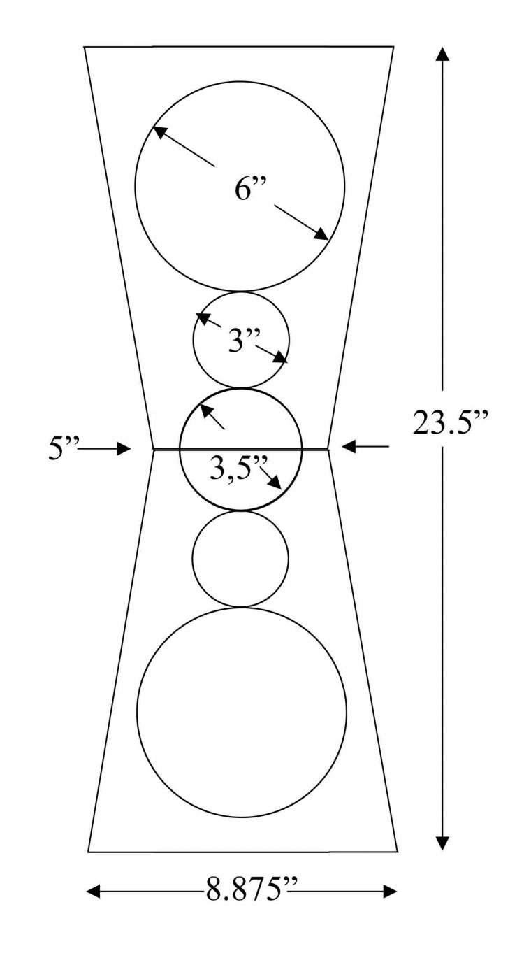
I'm in the planning stages for a new small bookshelf. It will be 23.5" high by 8.875" wide (at the bottom) by 14" deep. Drivers will be arranged in either a WMTMW or a WTMMW configuration. I was wondering what the pros and cons would be for mounted the midranges next to each other instead of flanking the tweeter symmetrically? The baffle round-over will be 0.75" radius all the way around. See attached baffle drawing.
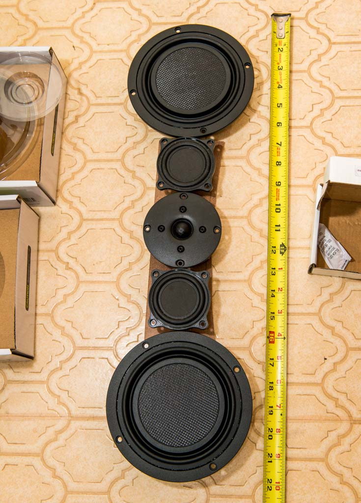
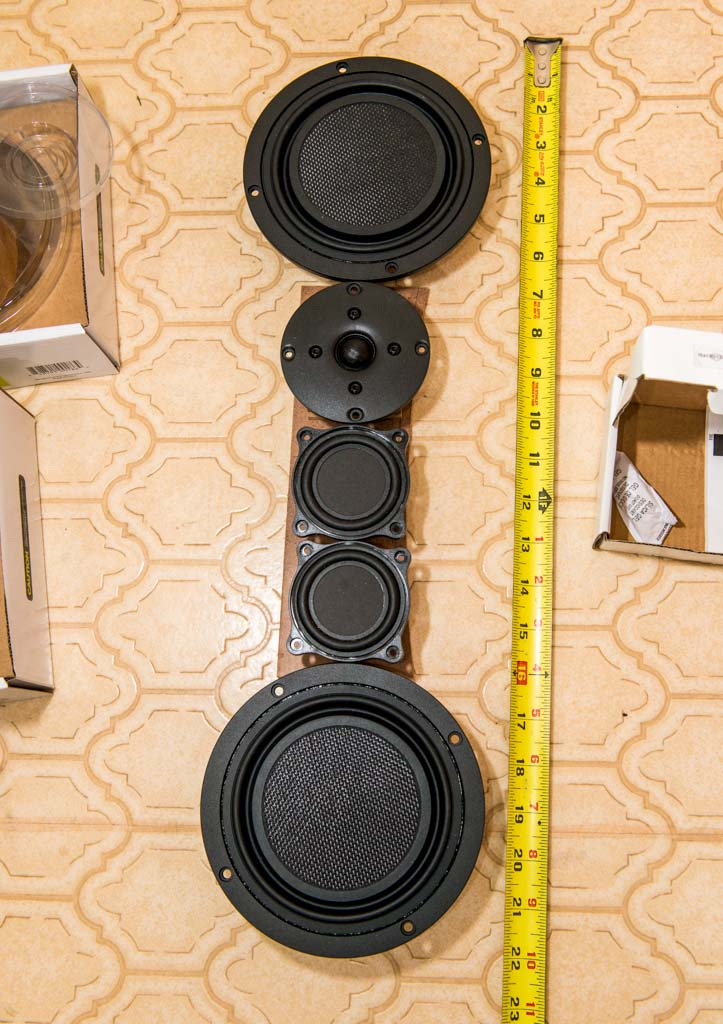
Drivers, per channel, will be:
Woofers: Two Dayton LW150-4 woofers wired in series for 8 ohms
Mids: Two Techtonic TEBM46C20N-4B wired in series for 8 ohms
Tweeter: One SB19ST-0004-4 3/4" dome tweeter
Tuning will be somewhere in the 40Hz range with an 8" long by 2" ID port. The upper and lower woofer cabinets will probably be separate. The mids will get a small sealed enclosure.
OPTION A:
OPTION B:
DRAWING:
Comments
I'd strongly recommend the MTM arrangement, otherwise you will have lobing and/or extra crossover complexity.
For these little Tectonics, you don't need more low end, because they will be pure mids.
I agree you could get a tilted down lobe but you can mange in the x-o. I would be tempted but only for a TMMWW where I can narrow the baffle for early transition to 4pi. If this is a real bookshelf and not a stand mount then ignore this...
Thanks for the feedback. I did some diffraction baffle board and driver placement modeling in VituixCAD which shows the WTMMW to be more consistent than the WMTMW in the horizontal domain. As you have indicated, the vertical domain will probably have some lobing issues. John, this is not a "real" bookshelf. The intent is to stand mount it well away from the rear and side walls. I am in the process of putting together VituixCAD models to see what the vertical diffraction signature looks like at various angles. I cannot model this baffle in EDGE because EDGE assumes sharp edges and cannot model the roundovers. I cannot model this baffle in any of the Bagby/Laub programs (Blender, Response Modeler, BDS, etc) because these programs can only model a baffle with 4 corners. When I get the VituixCAD models put together, I will report back with some vertical polar response comparison curves.
Bill
Hi Bill, very interested in how you setup the baffles and model them.
Thanks, Ani, attached below is the VituixCAD screen and diffraction model comparing the two midrange drivers at 0 degrees and 45 degrees horizontal. Notice the huge midrange glitch at 3kHz on axis using the WMTMW model. The WTMMW significantly reduces this problem because the distance from the center of each midrange driver to the sloping baffle edge is different. This spreads the ripple over a wider range of frequencies.
I also tested the tweeter horizontals in the two different baffle formats, but there was no clear winner. The only thing that happens is that the dips and peaks move around a little bit based on the different tweeter to edge distances involved.
I am putting together a model to test the vertical polars at different angles as well and will report back when done. In addition, I will be putting together a comparative model with all drivers mounted on the baffle with different crossovers. VituixCAD can only model one driver at a time on the diffraction screen, but if I design & save FRD's for multiple angles and drivers, I can then import these FRD's as separate drivers to complete an entire baffle model with xover. The tweeter will be modeled as a 0.75 diameter perfect piston. The mids will be modeled as 2" diameter perfect pistons. And the woofers will be modeled as 4" diameter perfect pistons.
Bill
Screenshot:
Model for midrange:
Model for tweeter:
Thanks Bill. I didn't understand about saving different drivers/angles FRD and importing. Could you elaborate on it please.
For modeling purposes, I am assuming that each driver has a perfectly flat FR with infinite bandwidth. Therefore, each individual diffraction model FRD file generated by the VituixCAD diffraction screen can be used as a proxy for the individual driver's FRD file. As such, I am going to load these individual FRD files into a modeling program, such as XSim, WinPCD, PCD, VituixCAD, etc., and use them in the same way that I would use the OmniMic measured individual FRD files to model a completed system with crossover. This will work to isolate the effects of the baffle shape and roundovers. I will be able to see how changing crossover order will affect the size and tilt of the vertical lobe.
The model will not be very accurate, because drivers are not perfect pistons with infinite bandwidth. But it should give me an idea as to how the baffle and driver locations are affecting the polars. I could do this much more accurately by building two test baffles with boxes, mounting all drivers, and then taking measurements. But I am trying to avoid building two test boxes at this point. Hope this helps.
Bill