Site Links
Howdy, Stranger!
It looks like you're new here. If you want to get involved, click one of these buttons!
Quick Links
Categories
In this Discussion
Who's Online (0)
The Zonkers - An isobarik 8" two-way

The Zingers, the Zangers, the Zoinkers, and now, the Zonkers! How does that sound? I had to glue up four of the shelves into 2x4 foot handi-panels in order to create the side, top, and bottom panels. This put a glue line horizontally around the cabinet, going directly through the center of the tweeter. To cover this up, I am going to paint a horse-shoe shaped racing stripe around the tweeters. (See pics showing the glue line). It should look interesting when I get it done.
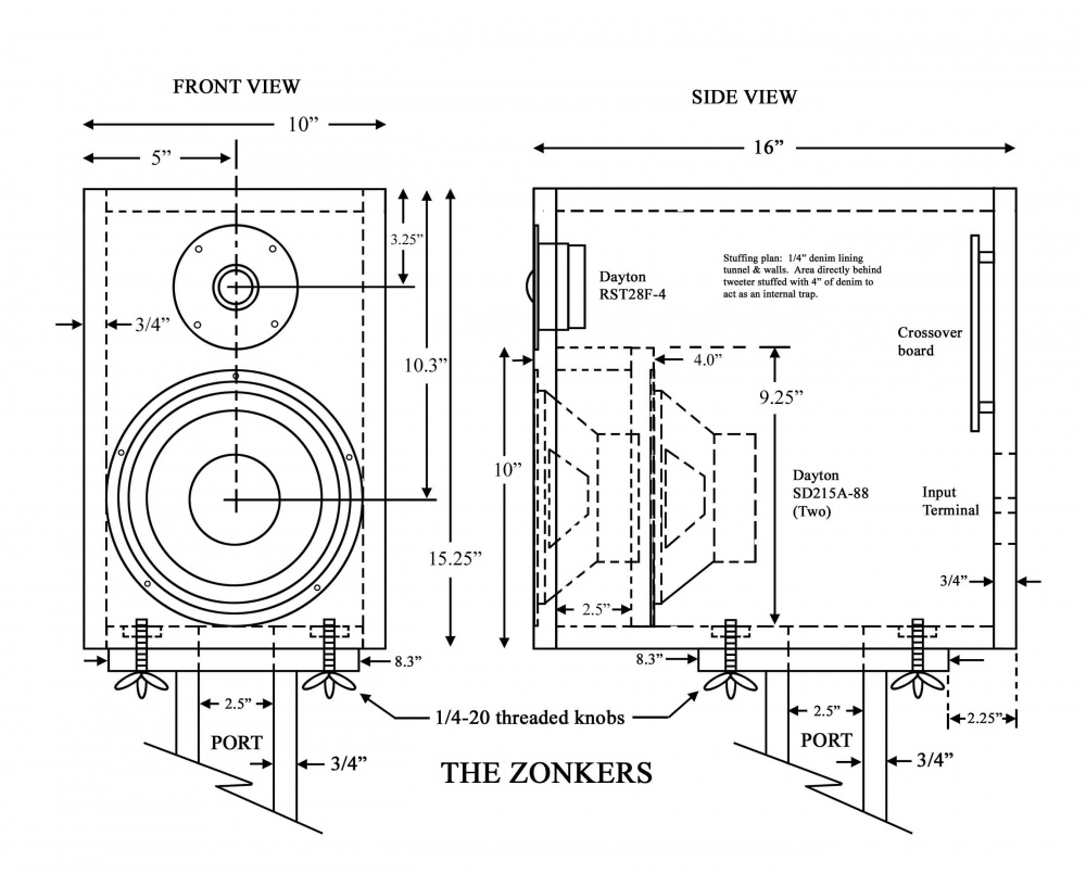
DRIVERS: One RST28F 1" dome tweeter and two SD215A-88 8" subwoofers per side. I bought a pair of SD215A's from Craig last year. Since then, PE put them on sale again, so I picked up another pair. My plan is to build an isobarik, which will cut VAS and box size in half. Should dig really deep in a very small box.
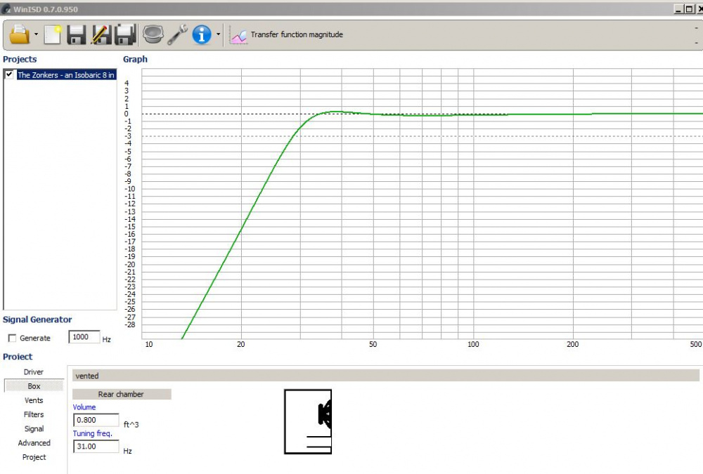
MAIN CABINET: See drawing below. Net internal volume, less the isobarik tunnel, will be approximately 0.8 cu. ft. Effective isobarik volume will be 1.6 cu. ft.
LUMBER & FINISHING: I picked up five pieces of 12" x 48" x 3/4" laminated "value shelving" at Menards for $0.99 each. This should be enough for both boxes and stands. Total lumber cost: 5 bucks!
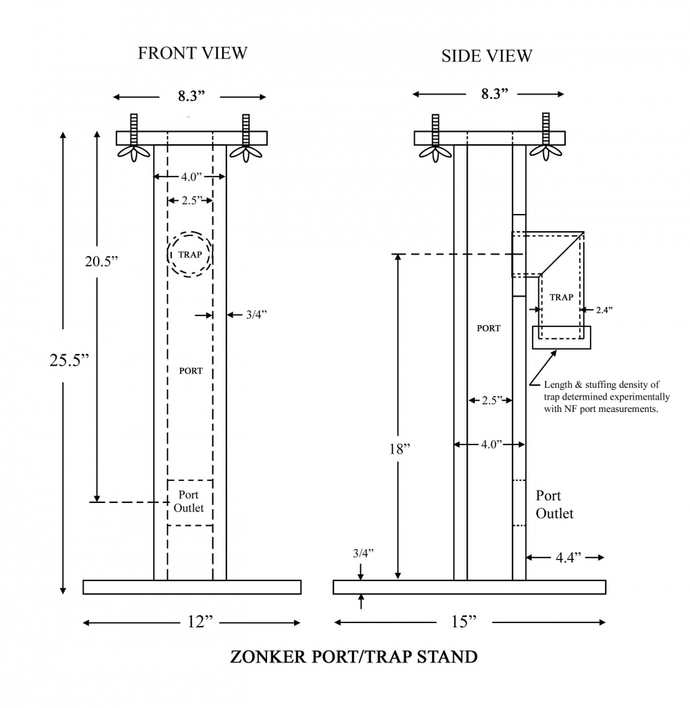
COMBO PORT/TRAP SPEAKER STAND: To save space, the port will be built into the speaker stand. This allows the port to be 20+" long using 2.5" x 2.5" inside dimensions. This also allows the use of a 1/4 wave stuffed trap at the end of the port, since an external trap/port system will be very easy to fine tune once the boxes and stands are built. Fb tuning will be 31Hz with an F3 of 28Hz.
ISOBARIK LOADING: The isobarik tunnel will act as an internal brace and will also help to break up internal mid-bass cancellation/reinforcement modes. The internal 4" space immediately behind the tweeter will be stuffed with denim and used as a resonant box trap. Also, the sealed off spacing distance of 4" between the two woofers will create a frequency response dip at 1.7kHz, which will help to suppress woofer cone breakup in the 1-2khz area.
TARGET EFFICIENCY: Since I will need to hook the isobarik woofers In series for 8 ohms, there will be an efficiency loss of 3dB. After BSC and tweeter padding, final system efficiency should be in the 84 to 85dB range.
CROSSOVER: Since the rear panel must be removable to install or remove the internal woofer, I plan to put the crossover inside as well. My initial target will be 4th order acoustical at 2kHz.


Comments
Nice! You could run the tunnel-rear up behind the tweeter and leave a hole in it for a trap, filled with Utouch.
I'm also thinking the cabinet will be really front-heavy with the stand positioned where you have it. Maybe a single 3/4" board in front of the port column to make the stand a T-structure would benefit there.
InDIYana Event Website
Ok, that would probably work. But then the volume of air in the isobarik tunnel would probably be significantly higher, which may increase the mass of the two woofer cones and change the alignment somewhat.
Yes, they will , indeed, be front-heavy. My solution was to have the base stick out 15" to compensate. If it bends forward under the weight, I'll add your suggested T-structure to make it more solid. Thanks for the suggestions.
Could document your trap tuning experiment data? Would like to know what you initially start with and where it ends up and why?
Are you starting towards the middle of the port with half the length?
I mean keep the tunnel the same as it is, and chamber off the tweeter in a trap. Don't increase the tunnel volume.
InDIYana Event Website
OK, now I understand. Good idea. I will definitely do this, as this will lengthen the trap and lower the tuning. Since the back will be removable, I will make this trap extension adjustable. Then I can fine tune this new "tweeter" trap based on NF measurements.
Will do. With the Plumber Delight speakers, I started out with a total port length of 26" and a trap length of 13". I ended up reducing the trap length to about 10" by trial and error. This port will be about 21" long, so I will start out with a trap length of about 10.5," slowly reducing this by trial and error until the 1st and 2nd port resonances disappear.
I will be placing the trap about 1/4 down the port length, as shown in the drawing. Previous experiments seemed to show that this makes no difference.
Ben, attached is a revised drawing and a few pics showing your suggested internal trap mod. Note the extended tunnel partition, which increases the tweeter trap from about 4 inches up to about 8.5 inches. The length of the 3 inch section will be fine tuned once I get the cabs done. Based on my rough calculations, the internal box resonant modes will range up and down from about 300Hz to about 800Hz. The predominate peaks will probably be in the 300 to 500Hz range, based on the major diagonal distances involved. This should work out OK, as I can adjust this trap from 5.5 to 8.5 inches, which corresponds to a suppression range of 474 to 307Hz.
My plan will be to press the 3 inch section temporarily in place with mortite caulking compound, re-install the back, take a measurement, and then trim this section length until I get the lowest peaking in the 300 to 500Hz range. Should work.
Internal trap tuning:
1130 * 12 = 13560 / 5.5 = 2465 / 4 = 616Hz * .77 fudge factor = 474Hz
1130 * 12 = 13560 / 8.5 = 1595 / 4 = 398hz * .77 fudge factor = 307Hz
The port will be about 21 inches long, and will have a first resonant peak of 322Hz:
1130 * 12 = 13560 / 21 = 645 / 2 = 322Hz
Ani, here is an on-line calculator for open and closed end pipes:
http://hyperphysics.phy-astr.gsu.edu/hbase/Waves/opecol.html
How do we read the f1, f2, etc. results of the trap calculator? Do they cancel out these frequencies? If the trap calculates to an f1 of 800hz., does this mean it reduces, or cancels a box resonance at this freq?
How does the internal trap work? Doesn't the trap need to be part of the vent , (coming off of the vent?). Did you move the trap from the outside to the inside, but it is disconnected from the vent and in a different airspace.
He has 2 traps; one on the ported-stand, and one behind the tweeter inside the box.
InDIYana Event Website
Wolf is correct. I am using two traps, one designed to reduce or eliminate the port resonance and one designed to reduce or eliminate internal box peaking in the 300-800Hz region. Both the port and the box are part of an somewhat interrelated air space, so one trap probably affects the other somewhat. I will not be able to see clearly what is going on until I finish the complete box/port system and start taking NF measurements. I will save all my NF data files and post a complete set of comparison graphs later.
The internal trap works the same as the external port trap. You create a recessed area within the box and stuff it with damping material. A quarter wavelength of the trap depth is your starting point for a tuning frequency.
f1 would be the 1st harmonic (or fundamental), f2 would be the 2nd harmonic, etc. If the trap calculates to an f1 of 800Hz, this does NOT mean that it reduces or cancels a box or port resonance at that frequency. Reality does not match the calculator. The calculator would only give you a starting point. You need to take NF measurements and watch the computer screen peaking as you adjust the length of the trap and stuffing material density. It is somewhat of a trial and error type guessing game, but it works.")
To clarify, here are a couple more pics showing the internal box trap profile and how I intend to tune it. The bead of brown mortite caulking compound on the adjustable partition will hold it in place during NF measurements. I will start out with a 3 inch partition and shorten it in 1/4" increments between NF measurements. When I find the right length, I'll remove the caulking and glue it permanently in place with yellow wood glue. (Edit: The baffle board, side, and back panels are missing in these photos. When the baffle board and side panel are installed, the trap will be sealed off.)
Bill, your energy is enviable.
I glued up the cabinet shells and cut the baffle holes this morning. The RST28F solder lugs stick out the side from the tweeter magnet assembly by almost 1/2", so I had to rout fairly big clearance ears (see pic). This gives more room for the lugs, but could potentially cause an air leak around the edge of the gasket. I was very careful to avoid this, but if I have a tuning problem later on, this is the first place I will check.
Thanks, JR. Have you started your Octozaenger 8" 2-way project yet? Looking forward to seeing what you come up with.
I'll likely use a Human Speakers Pro001 in 0.75 cubic feet, sealed. F3 of 47hz, Q of 1.0
This morning, before gluing the baffle boards in place, I lined the isobarik tunnels with 1/2" thick fiberglass. I used Armstrong Pebble fiberglass ceiling tile, which is sold in 2x4 foot panels at Menards for about $7 each.
I also drilled holes for the 16 ga isobarik connecting wires and then silicone sealed the hole to keep everything air tight. Then I added extra fiberglass in 3 of the 4 corners. This should help to dampened the main cross sectional peak resonance, which calculates out to about 542Hz (1130 * 12 = 13560 / 12.5 inches = 1084.80 / 2 = 542.4Hz).
I have used those same ceiling tiles for damping on a few projects and they worked great.
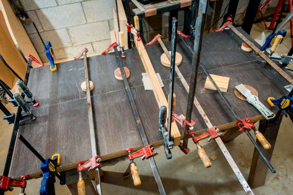
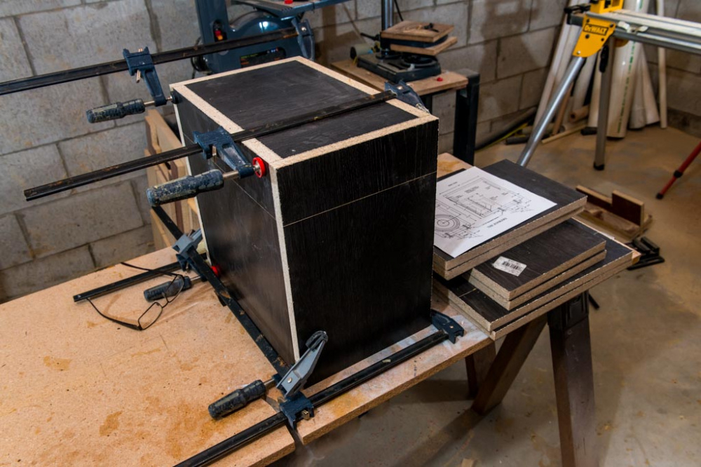
Last night I glued the baffles onto the main cabinets. First, I marked and sanded the glue surface areas on the back of the baffle (see pic). This was necessary because the baffles are laminated on both sides and this smooth, laminated surface does not stick very well to yellow wood glue. But if you sand it with 40 grit, the glue adheres almost as good as bare wood.
Then I applied a generous bead of yellow glue to both the baffle edges and cabinet shell edges (see pics).
Then I flipped and set the cabinet shell onto the baffle. The weight of the cabinet (about 15 lbs) applied enough pressure to create an initial "tack." After careful alignment, I starting putting on clamps. This gave the glue about 5 minutes to soak into the wood before I applied higher clamping pressure. I double checked to make sure that I didn't glue the baffle on upside down! That would have been really bad. Come back the next day only to find out that the tweeter hole lines up with the isobarik tunnel!
I got that right, but then this morning I gouged the baffle when doing the roundovers. (see pic). It doesn't look too bad, I should be able to fix it with a little bondo.
Ouch! I had that happen to me once.
Yeah- been there done that! I always now use the flat side for the guide-bearing. Cutouts have hindered my corners more than once.
InDIYana Event Website
This morning I drilled 12 holes in the back panels to accept #8 x 2" long sheet metal screws. As you can see, the 4 corners stick out proud due to the 3/4" roundovers along the sides.
So I countersunk the flathead screws and flush trimmed the back panels all the way around.
Then I rounded the sharp edge with a 1/4" roundover bit, set to a depth of about 3/16." This eased the rear edge a little bit, but still kept the delicate router bit about 1/16" away from the screw heads. I think it gives the removable rear panel a really nice look.
Rear panel input terminal cup holes will be cut after I do measurements and order xover parts. The terminal cups that I have on hand look cheap and I want to find something better. Any tips on good quality terminal cups that can be flush mounted to the rear panel? My problem is that most of the flush mount types seem really flimsy, whereas the more expensive types are not flush mount, and stick out the back too far for my taste.
Use posts, and an inner-mounted board across a recess hole.
InDIYana Event Website
I have used the SD-cup and the TD-cup from meniscus and liked them both. Dayron also makes some nice binding post.
Javad seems to have started a craze with the intigrated wooden terminal cups that is a nice looking option that keeps the back flush.
What wooden terminal cup?
Ani, Ken just means like I suggested. It's been around a lot longer than just Javad doing it. Even Joey's RS 8" 2-ways resemble the type.
InDIYana Event Website
Looking good! I don't know why but I like this look with the exposed edges - would be kind of fun to build a set of speakers like that and just slap some finish on them")
With that approach, if you size things right, you can mount the crossover on the inner mounted board, have posts feed the amp side directly, and have it be removable from the back if so desired.
Sehlin Sound Solutions