Site Links
Howdy, Stranger!
It looks like you're new here. If you want to get involved, click one of these buttons!
Quick Links
Categories
In this Discussion
Who's Online (0)
Walk me through amp project - UCD32MP

With all the cool amp projects going on this forum, I dug through my inventory of bits and pieces and found 4 amp boards which can turn out to be a decent project. I need a lot of help and walkthrough this amp project. This would be the first amp project where it was not just plug and play. It's still easy, and can be expanded upon a lot. it's cheap (I paid 40$ for 4 modules), so can go up in smoke if required, but would prefer not to.
These modules are very old (hence the cheap price) and would be easily left in the dust compared to newer amps, but for the price and the fact that I get to learn how not to electrocute or burn my house down, would be worth it. Of course all the paraphernalia that goes along with building an amp would cost a lot more than the amps themselves, but let's get started.
I want to go for an 8 channel amp, housed in the same chassis, powered through one IEC switch/fuse. Next steps, add in soft start/speaker protection and add in volume control for all 8 channel (analog or digital) - it has a input block and can be controlled by a micro-controller - once the basic amp is working, i would like to explore those options. I am not aware of all that is possible, so if there is something that can be tried, i would like to try.
Also, please assume that I do not know even the basic safety principles - so please highlight whenever there is something to be aware of. I can and did watch a lot of youtube videos (but they are no substitute for education / lab/hands-on work) and I trust this group far more than any you tuber.
Comments
This is the spec sheet / manual for the UCD32MP. These modules are sol old, these are not even on the Hypex site anymore.
I have 4 of the 2 channel models. The manual shows 2ch, 4ch and 6ch. I have the 2ch modules.
So, where and how do i start? and what do i need?
Even more basic question, What wire do you use for wiring up amps? All i have on hand are various gauges of speaker wires. The amp modules do have the harnesses...
Well, those have ps built in, so almost plug and play.
Do you have pictures of the cable harnesses?
First thing will be the case to fit the modules.
For mains wiring just get a decent fused/switched iec socket and correct color cables. I guess you can get by foot electric cable in home depot or similar stores.
Brown = line
Blue = neutral
Green or green/yellow = earth
Get at least 14awg. If you can, the harness might be the limiter.
While we are in mains, get a grounding lug/nut for your earth.
To wire to the iec, faston connectors either isolated or covered with heat shrink will work well. You will need a crimper.
That looks like balanced input like the other ucd, so you'll need the appropriate connectors, get one model with direct grounding for pin 1 to make your life easier. Or metal bodied ones to accomplish the same with ease.
Any switch rated for +200vac should work, I like the look of the anti vandal ones with ring light.
Since it has standby operation, you can use the second switch for standby and the iec as power switch. Or add a switched mono 2.5mm jack and add a trigger. Or make some convoluted solution.
Ani, you can get THHN wire at any hardware store, you can use other types, but make sure that the insulation is rated for line voltage. 14 gauge vwire is good for 15 amps and 12 gauge is good for 20 amps.
The neutral in the United States is generally white on 120v circuits, with black, red or blue as the hot.
Typo Nick. 12 gauge is good for 20 Amps.
Yep, thanks. Fixed it.
I don't like THHN for my amp projects. It's just too stiff.
Agreed, but it is easy to source. I have some 18 ga that is workable for lower power stuff.
You can get pliable cables from a power cord extension and will likely be the correct color.
Thanks for the tips on the wires. These are not very power hungry amps, the amps is rated for 100 watts, but I do want to connect all 4 of them in one box and going to a household circuit. All 4 gets connected in parallel after the fuse?
Iec -> mains switch -> fuse -> amps in parallel? Are there iec receptacle with built in fuse - would be preferable.
Yes, parallel, yes you can get fused and switched iec.
Parmetal should have cases that can fit your modules.
Here's some close-up of the board and connectors harnesses.
Will try to get better snaps, the lighting is horrible, but the mains connector has the blue/brown wire. The speaker connector has the black/red/black/white wires. The connector for +5v/V-/GND/V+/Amp_En/DCERR is all black wires.
Also, looks like the serial cable looking wire is used for Audio in. The manual says, Inverting Audio Input Ch1, and Non-Inverting Audio Input Ch1.
What is inverting and non-inverting audio input?
can i use something like this? Also, how do i make a big rectangular cutout in the project box?
https://www.parts-express.com/IEC-AC-Power-Jack-Chassis-Mount-with-Switch-and-Fuse-Holder-090-978
Drill an then use a nibbler, and clean it up with a file.
Inverting is negative, non inverting is positive, ground is ground. Thus, this is a balanced input.
J9 and it's harness is not completely needed. Unless you want to use the same 5v standby to switch all the amps.
All the fun parts are in J2.
J2 has the inputs, has the SMPS enable and Amp enable.
SMPS Enable Characteristics
Connect this pin to +5V Standby to enable the SMPS. All amplifiers are running but muted.
Amplifier Enable
Connect this pin to GND to unmute all amplifiers.
You can use the ribbon and cut the end or get the same type of connector and use discrete cabling.
Basically you have to connect J2.1 (or J9.2) to J2.4 to power up.
And J2.7 (or J9.6) to ground (I guess J2.8) to unmute the amp.
J2.9-12 for your inputs.
And have fun!
Thanks for the explanation. What is this connector called and how do i do the discrete cabling? Any special crimp tool or something required? Also, I want to add in some sort of switch to power on the smps / amp. So mains switch for the power from IEC, then indiv switches to power on the amp. So if i am only using 2ch active speaker, then i can power on only two modules vs all 4 (8 channels) being powered on If i do a hard connection between J.21 to J2.4 and J2.7 to J2.8
I didn't knew such a tool existed - appropriate name!
Not sure what connector is that in particular, likely the same used in the ncore line.
Yes, you can add switches or relays for the SMPS enable and/or amp enable.
Edit, well it says 2x10p 2.54mm box header
So, for balanced input, Should i run XLR connectors or XLR/TRS connectors? Can unbalanced be fed to a balanced input, or some way to convert balanced to unbalanced? Would a simple RCA to XLR cable work or some input buffer is required.
Sorry, most of these terms are second/third hand overheard.
So, this is based on the ucd32 OEM
https://www.hypex.nl/documenten/download/1145
Looks like 30w per channel.
The 100w of the MP seem to be PSU related.
It needs an input buffer or a source that can output 5v and drive the low input impedance 1.8kohms.
From the bigger brother ucd180 OEM, you can see the input buffer used by them.
https://www.hypex.nl/documenten/download/1221
I have 18 gauge AWM hookup wire in black, red and white and 16 gauge MTW in red, black and blue if you need it.
It looks like there are semi-conductors on the edge of the board that need to mount to the case and/or a heatsink. I have a bunch of 3 x 4 1/8" heatsinks that will mount to a flat panel if that helps.
Ron
And you need standoffs. They recommend at least 6mm away from the case.
Thanks Ron! I don't think any heat sinks are required for these amp modules, but i'll keep in mind for any other amps that i do that might require them. It will be easier to just grab a spool from Menards for the hookup wires. I'll get some light and heavy gauge.
What does this mean? Is this a pro vs consumer sort of thing?
Is an input buffer required, if i drive the amp with balanced signal - i do have a DAC that balanced out that i am currently using with the Ncores (I didn't build it though), but it is a consumer DAC.
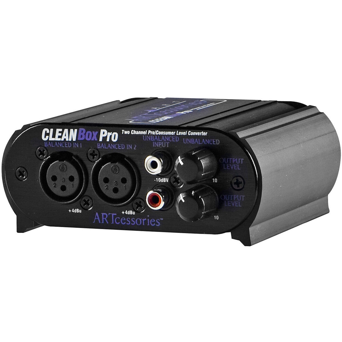
I also have a ART Clean Box Pro from stepping up unbal to bal and voltage from consumer to pro which I am using with my Crown Amp (the previous model, which didn't take low V RCA). Would this be a better option?
https://www.parts-express.com/ART-CLEANBoxPro-Stereo-Balanced-Unbalanced-Converter-245-868
For the input buffer - it might be a bigger bit to chew off right now, but is this the input buffer (I am unable to even recognize what a input buffer looks like) - is the Mute/unmute interface?
From the UCD32OEM PDF