Site Links
Howdy, Stranger!
It looks like you're new here. If you want to get involved, click one of these buttons!
Quick Links
Categories
In this Discussion
Who's Online (0)
SoundEasy V26 - Help needed with impedance measurement issues

Hi Everyone,
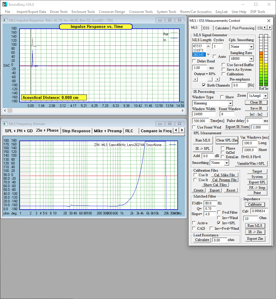
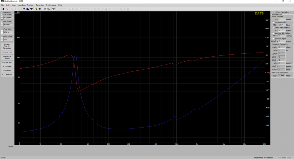
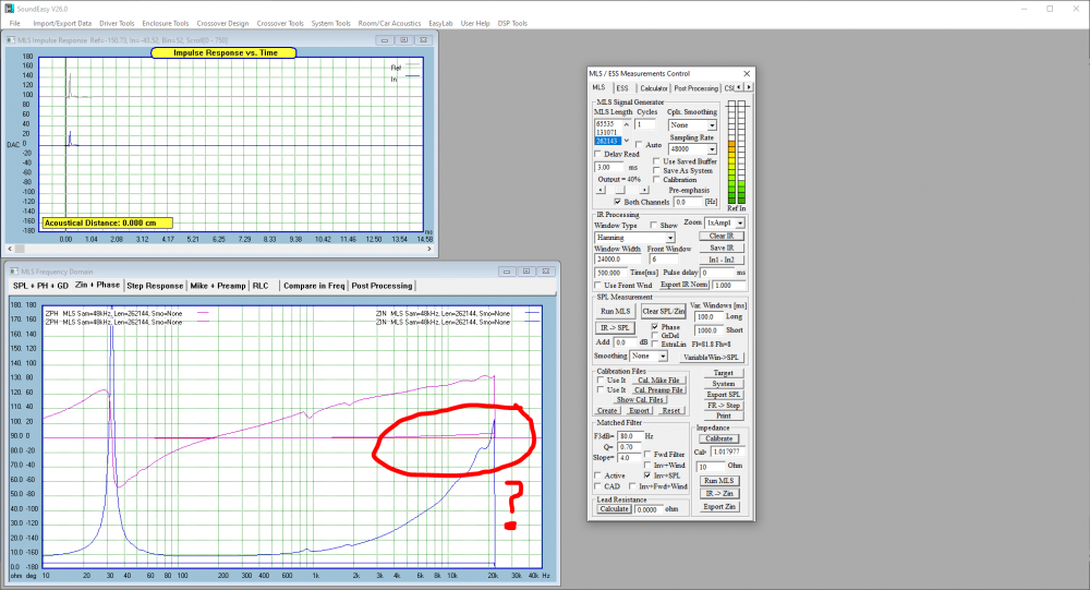
Tagging @Archer60x and @dcibel as I know you guys use SE, but anyone feel free to help! I'm looking for some help measuring impedance curves with SoundEasy. I'm getting my feet wet here... I picked up V24 off the door prize table at InDIYana this year and paid to upgrade to V26/V27. I built a measurement jig following instructions from the Audio Judgement web page (https://audiojudgement.com/soundeasy-measurement-box-build-guide/), so now I'm trying to measure impedance on a Wavecor SW275BD02 driver. Something isn't going well though... the impedance signal I am measuring is flat out wrong. I know the driver is OK because I get exactly the same impedance curve when I measure the driver using DATS V2. SoundEasy is not showing me the 100 ohm Fs of the subwoofer near 30 Hz, and claims a rapid rise to >180 ohms after 2kHz, before dropping off at 20kHz. Has anyone seen something like this measurement result and know what to double check? Thanks in advance for any ideas!
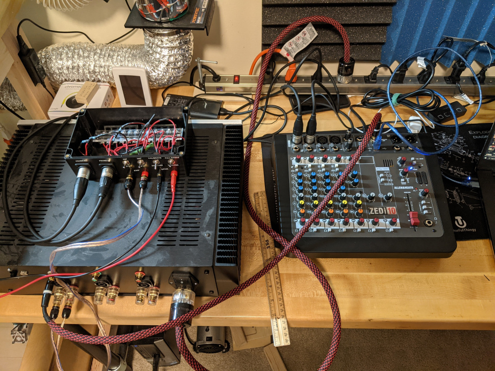
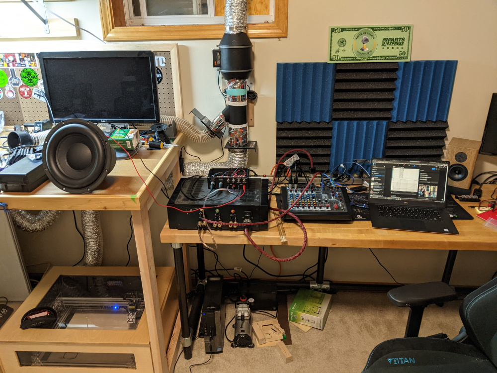
My measurement system:
Dell XPS 9370 running windows 10 (latest)
- Allen Heath drivers installed
- All "audio enhancements" in windows disabled
- Inputs / Outputs set to 24 bit / 48 kHz sample rate
Allen Heath ZEDi10 mixer used as a USB interface/soundcard (24/192)
- Sending SoundEasy MLS signals out to the mixer via USB
- Sending RCA output signal Left channel only to the amp
- Returning Reference Probe (#1) via XLR to mic channel 1 on mixer (panned hard L)
- Returning Input Probe (#2) via XLR to mic channel 2 on mixer (panned hard R)
- USB return signal to PC/SoundEasy
Measurment Amp
- Hypex Ncore NC502mp (one channel only)
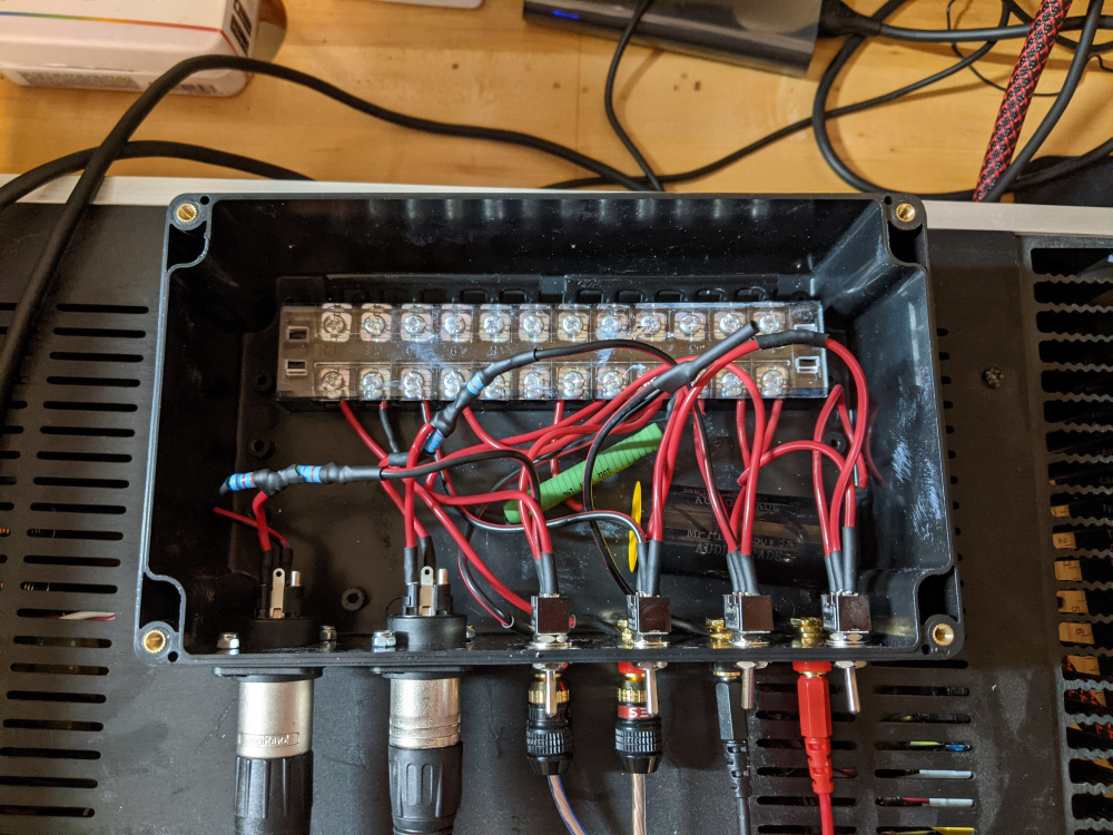
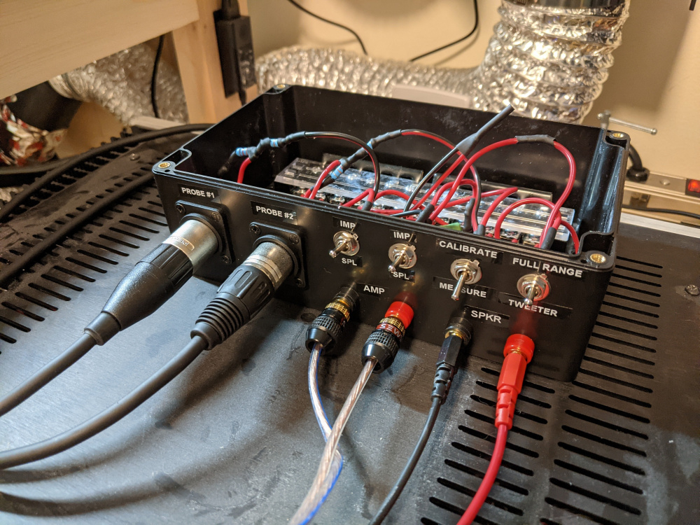
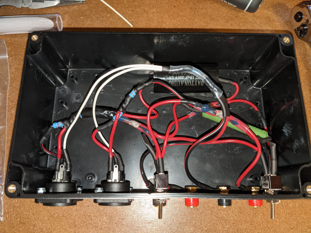
Homemade measurement jig
- 10 ohm resistor for impedance calibration
- 18uF capacitor for tweeter-only SPL/FRD measurement
- 22kOhm and 47kOhm resistors used as sensor probe voltage divider networks.
Things I've tried so far
- Confirmed I have the USB inputs/outputs correct (I think I do)
- Quadruple checked my jig for mistakes (I think I'm good)
- Used the O-scope function to measure 1khz sine sweep into a 4 ohm resistor (both probe signals looked correct to me)
- Did a loop-back test to confirm I don't have latency issues with my soundcard (no problems there)
- Switched my probes just to try it and see if any difference was made (negatory).
So... I'm currently out of ideas! I'd like to think my audio interface is OK. It'll cost me somewhere around $100 - $150 to buy a different interface, but that doesn't seem like it's the most obvious problem. Any other thoughts are apprecaited.
Thanks,
Keith
Comments
Sure looks like you inadvertently created a high pass circuit somehow.
I haven't tried removing the tweeter protection cap from my grounding bar in the back. Since that is connected to the other end of my full range vs. tweeter switch... it shouldn't be getting used... but I'm a mechanical engineer. What do I know about angry pixies and electrical voodoo. Can't hurt to try.
I had a quick look at the schematic at Audio Judgement and it is confusing, over complicated and at least slightly incorrect.
There doesn't need to be 2 switches to select SPL or impedance measurement, the leftmost switch can be deleted completely, it doesn't do anything. It also looks like the tweeter cap is in a poor location. For a 2 channel measurement system the cap should be located before the reference probe so the system self-compensates for the cap insertion. This would be at the amplifier input in the jig, not the speaker output where it's shown. When using Soundeasy, unless you have amplifiers that make big pops or are prone to connecting RCA connectors live making a BZZ sound, you can generally avoid the cap all together and use the pre-emphasis feature in software.
Anyway, I would first start with a simple loop back test without the jig, make sure that soundeasy will measure a flat line without error. Then the most likely error if all the wiring is correct is a switch installed upside down, in which has you may have a cap included or be selected for SPL even though your switch labels say otherwise. Beyond that, check the wiring and then check again. Get your meter out and verify the switch continuity in all switch positions.
I can't follow you photo, but if all those terminals at the back are common ground, the cap doesn't get connected to ground.
Thanks @dcibel - I have done what I hope is a good enough loop back test and confirmed I can measure a straight line. The instructions I read said to use only one channel of my output with a Y-splitter to loop that back into the mixer, but that did not work with my 1/4" cables... only with my XLRs. SE didn't record any impulses with the 1/4" input but DID with the XLRs. I hope I didn't fry those 1/4" inputs somehow... Anyway, here's the measurement I got. Let me know what you think.
As for the switches in the box... I did pull my multimeter out and I do think I wired them up wrong. Continuity wasn't what I expected. +10 dumbass points for me, 'cause that certainly doesn't help things! Maybe I order a second $8 project box on Amazon and redo it with only 3 switches.
Finally, the big bar in the back is divided into two sections. The jumper forks in the back are cut in two pieces so I have one bank on the left, and another bank on the right. Seemed easier than dealing with two separate bars in the small box.
Other than both your signal and reference impulse being inverted, the loop back looks successful")
If you want to simplify, when I rebuilt my jig in a nice box I downgraded to only a single switch, and just a single pole off/on switch at that. Originally I had 2 switches as I had a calibration toggle, this was because the SoundEasy documentation listed to relocate the two probes to the same point for calibration, so they both see the same signal. Reading on in the ARTA documentation, they had you simply disconnect the load which works easily as well, so I ditched the switch and simply disconnect the speaker for calibration, works just as well in ARTA and SoundEasy.
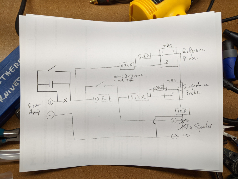
Some other thread here I posted this poorly drawn schematic of my simple jig. To switch from impedance to SPL I simply flick the switch, then manually disconnect the impedance probe and plug in the mic to my audio interface. To take this a step further you could add a couple connectors on the box and a switch for the mic so you can leave the probes permanently connected if you like, you can find detail of this in the ARTA jig application note.
This drawing isn't that bad actually, just the 1kohm resistor is out of place, it is in the box obviously, not external on the speaker wiring. If I want to add in a cap I would connect it on the amp input side like I said. The benefit here is that the cap is included in the reference measurement so it's effect on the response is compensated for, however you will see rising noise with lower frequency as the signal drops off.
When you get your jig sorted out, first try measuring a resistor or two to verify that it measures the correct value and in a flat line.
Just want to add that I use TRS specifically because most (probably all) pro audio equipment with dual TRS/XLR inputs will put phantom power 48V to the XLR pins, but not the TRS pins. Using the TRS cable guarantees that I won't have 48VDC running down my impedance probe to the speaker and amp.
If you don't have it you should definitely pick up the SoundEasy Design Guide. It was written for an older version but covers the basics. musicanddesign.speakerdesign.net/Guide.html
You should confirm your setup is correct by measuring a known resistor.
Ron
@dcibel - thanks a million for the schematic. That is much simpler, though I have questions about the tweeter capacitor and the 1kohm resistor. First, If we're moving the cap to the amplifier (+) side before the reference probe, why not make it a SPDT switch there? If we put that cap into place without a bypass option, how do we measure full range impedance for other drivers? I understood your rising noise comment to mean that the capacitor was installed all the time regardless of driver being measured, thus a 1st order high pass on everything. I made a sketch off your sketch below to relay the idea.
Next the resistor... what is that 1 kohm resistor between speaker + and pin 3 of the TRS probes for? And is it paralleled across speaker + and - as well as both pin 3's?
I like that project box. Simple and sturdy... I think I'll go price something out and see what it comes to with TRS connectors. 48VDC sounds like a very bad day for any driver... like the stupid expensive driver I was currently trying to measure impedance on! I don't want to purchase a replacement $600 sub driver because I accidentally fry one!
Thanks Ron. I did pick up the last guide John K wrote (version 4) from the Music and Design archives. I used that to walk myself through the loopback measurement, and I'm sure I'll be referring to that frequently once I get my jig setup correctly.
No, not like that. The cap needs to be in series with the speaker. Like this, and you only need SPST to bypass it.
The resistor simply connects the amplifier negative to the probe negative to ensure that they are always at the same potential. I fixed my sketch above to make it more clear. Keeping all common "negative" points at the same voltage is important for this whole operation to work, and the 1k resistor is to dissipate any stray current due to any small difference in voltage between the amp and soundcard. Usually there is none to begin with because you have everything plugged into the same household circuit etc. It doesn't have to be 1K, but somewhere between 100-10000 ohms On a similar note, do not use the jig with any bridged amplifier output like most low cost class-D solutions. I think you mentioned you're using a high end Hypex amp which is fine.
Don't think that the 48VDC from your mic preamp is going to fry a subwoofer, these phantom power things are generally only capable of a few milliamps. Your sub will be fine, but your RAAAAL might not like it much. Additionally, there is a 47000 Ohm resistor in between the TRS connector and the speaker, so the speaker won't see much of that voltage, but best to be avoided anyway.
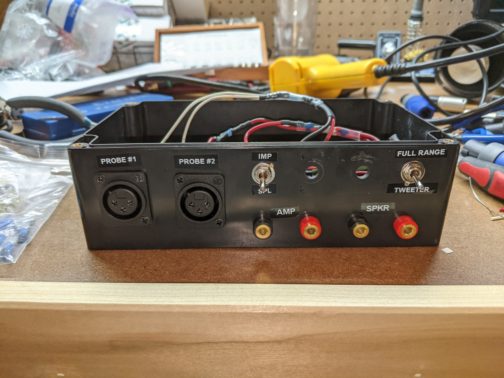
Alright Gentlemen. Some good news! I decided to remake my jig with the parts I had and follow @dcibel's instructions. Now I get an impedance sweep that actually makes sense! I also followed @Ron_E suggestion and measured a 4 ohm resistor as my load to see if it showed a 4 ohm "impedance." That also worked well, though it did show me a bit of phase rise at the higher frequencies. I am not sure if I should see that behavior or not... anyone know?
As the discussion previously showed, the jig is much simpler on the inside now. I tied speaker (-) and amp (-) together, and connected those to pin 3 on my XLR connectors with a 1kohm resistor in series between them. I kept a switch for full range vs. tweeter measurements too, just to keep my options open. I used my SPDT ON-ON switches to avoid buying more parts, I just kept the unused leg capped off so it's an open circuit. Sure there's two 1/4" holes in the box now... but I don't mind. Especially at the avoided cost of more switches, boxes, and jacks.
Assuming there's nothing to address with the phase rise on resistor measurements, I think I'm done making my jig, and can start working on more SE learning. Please let me know if you guys see anything in these posts that I should pay more attention to in the future.
Thanks!
Keith
Great news!
The resistor and test leads include a small bit of inductance, the phase is rising because the impedance is too. Zoom down to a 0.1 ohm / div scale and you'll see. 27 versions in and SoundEasy still doesn't have a proper lead compensation, recently I convinced Bohdan to add the lead resistance compendation which will remove the lead resistance from measurements needed for accurate measure of small resistors and inductor DCR, but it is just a single value compensation that shifts the entire measurement by the value entered. You'll have to switch to ARTA to employ complete resistance and inductance compensation for the test leads. SoundEasy simply instructs you to keep the probe resistors as close to the measured device as possible, in other words SE's recommendation is to not use a nice jig in a box")
To complete the lead resistance compensation in SoundEasy simply short you leads together and measure, then press that lead resistance calibration button to compensate. If you change to different leads you can repeat this process by entering in a 0 in the lead resistance running the shorted lead test again.
(of course, make sure that the jig is set to impedance before shorting the leads. You can short them in this mode because there is still a 10 ohm resistor across the amp. SPL switch bypasses this resistor and will short your amp)
IIRC the wiggle in impedance at high frequency in your screenshot is likely a sample rate issue. Check that soundeasy and windows settings are exact match for bit rate and sample rate.
OK, time for a thread hijack!
Someone recently posted a simple, but non-trivial crossover that they said resulted from a Soundeasy optimization run. So it got me thinking - sometimes a crossover will take me lots of time and lots of measurements to "nail", and wouldn't I save a lot of time and frustration to let the software do the work.
So is there any other practical way to automatically optimize a crossover?
I think the $250 for Soundeasy looks like a no-brainer.
Well given my experience I'm not sure I'd agree that the price of SoundEasy is a "no-brainer". It is old clunky software that hasn't kept up with the times of multi-core processors and user interface design. In discussions with the developer, we had disagreements over seemingly simple math and situations where the software would load data incorrectly were a "user problem" rather than a software issue that should be resolved in code.
As a result of my frustrations, I have moved away from SE to ARTA and VituixCAD. ARTA license is only USD$100 and VituixCAD is free, so the value is certainly greater with that combo. VituixCAD offers a lot more modern user friendly interface, 1000% faster code, and a slightly more advanced optimizer IMO as it can optimize to overall power response or listening window, where the power response in Sound Easy doesn't seem to even follow standard conventions as it is split to individual horizontal and vertical power response. The design of VituixCAD is based around a modern standard CTA-2034-A for measurement and presentation of "spinorama" data which I think is a great move.
As far as the optimizers go, they certainly save some time by getting component values 90% of the way there, but they won't design your crossover for you. You still must determine the topology, how many components needed to shape the response and how to arrange them, and decide on what is "optimal".
Thanks dude!
I've used ARTA many times, and like it better than Omnimic in some ways.
Looks like I need to finally learn VituiCAD. I really hate apps with a steep learning curve!
Thanks for the sanity check on the optimizer. Makes a lot of sense that they don't have AI (not yet)
The simplest crossovers I've ever seen were done by Jeff Bagby. I assume he used the Years Of Experience optimizer
I use SE and probably will continue to do so because I know how to make it do what I need to do but it certainly has its shortcomings. I think the documentation is geared toward someone that already knows what the program does. I also don't like the lack of a useful way to document what you've done. I print screen all the results because the print functions in the program are a joke. Some print functions give you a unusable thumbnail and some leave the print dialog box in the printed output.
Ron
Omnimic is great for in-room measurements and tuning of a finished system, but for design purpose the 2-channel measurement is definitely the way to go.
If this is your mentality then I can say that you will vastly prefer VituixCAD, and being free software there is no investment to give it a try other then your time. Start by reading through the measurement doc for ARTA here. If you want to generate the full 360 degree measurements for the spinorama then you'll want to get an ARTA license so you can save the impulse response files, they can be bulk processed in VituixCAD. I am happy to help as well where I can, easiest way to chat directly is through my Discord channel here.
I paid for ARTA many years ago, best investment in this hobby. Eleven years and counting and still no upgrade charges. Have tested it on Win2K, WinXP, Win7, and Win10. Not once have I needed to open Control Panel and dick around with anything.
I will be watching some tutorials on YouTube re. Vituix. I really like the free form modeling that Xsim offers but it is pretty limited otherwise.
I agree!
Recently on Facebook, Andrew Jones jumped into a thread and said "Folks, never be afraid to throw crossover parts at a solution. There is absolutely no problem with a complex crossover, or advantage to a simple crossover".
Remembering our dearly departed Mr JeffB, I held my tongue.....
Man oh man, that is so effing primitive! Shame on Bogdan...
Yes to both. I need to setup ARTA with a 2 channel measurement box. Learned to use it years ago thanks to a great tutorial by Charlie Laub.
Thanks for your Discord channel!
I have done 2-way crossovers with as few as three components and 3-way crossovers with over 20 components. I am not convinced either extreme possesses inherent advantages over the other - whatever it takes to hit the objective is the correct number of components.
The more I read about SoundEasy from both a UEX and business model perspective, the less interested I am in ponying up for it. If I want a clunky outdated interface with weird support I can still download Speakerworks.
Damn, Speakerworks was a great program! Too bad the author never updated it.
However, I am very interested in UEQ functionality, so....
Some alternatives to UE for PC based crossover solutions:
http://www.lupisoft.com/
https://juicehifi.com/
https://dephonica.com/
For SE users, V28 is released. Claims some improved polar data system including CTA-2034-A charts and ability to work with an automated turntable for gathering off-axis data.