Site Links
Howdy, Stranger!
It looks like you're new here. If you want to get involved, click one of these buttons!
Quick Links
Categories
In this Discussion
Who's Online (0)
Difference in woofer response

in DIY
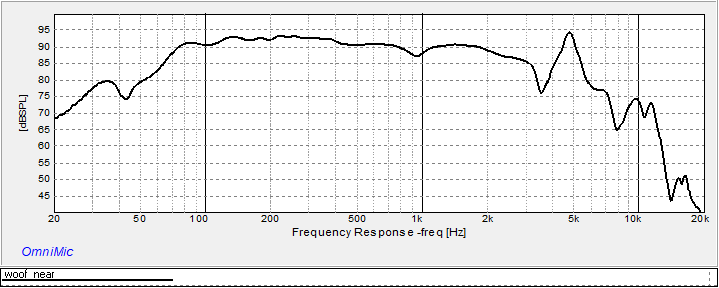
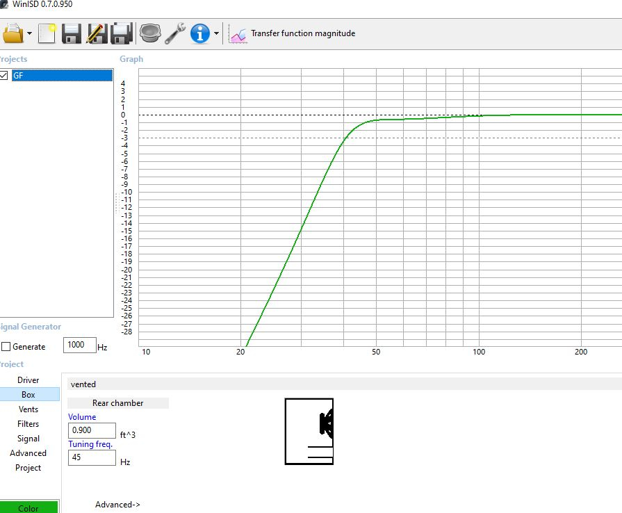
I'm working on a build with the GF180 woofer and have run into an issue with the low end of the woofers response. Basically the woofers response just tanks at just under 80hz. WinISD shows the response down to about 50hz before it rolls off.
Nearfield woofer response,
Modeled response,
I have double checked the T/S with Dats, tried the other woofer(only have one box built so far), double check polarity. Could it be because the port is located at the bottom of the enclosure?
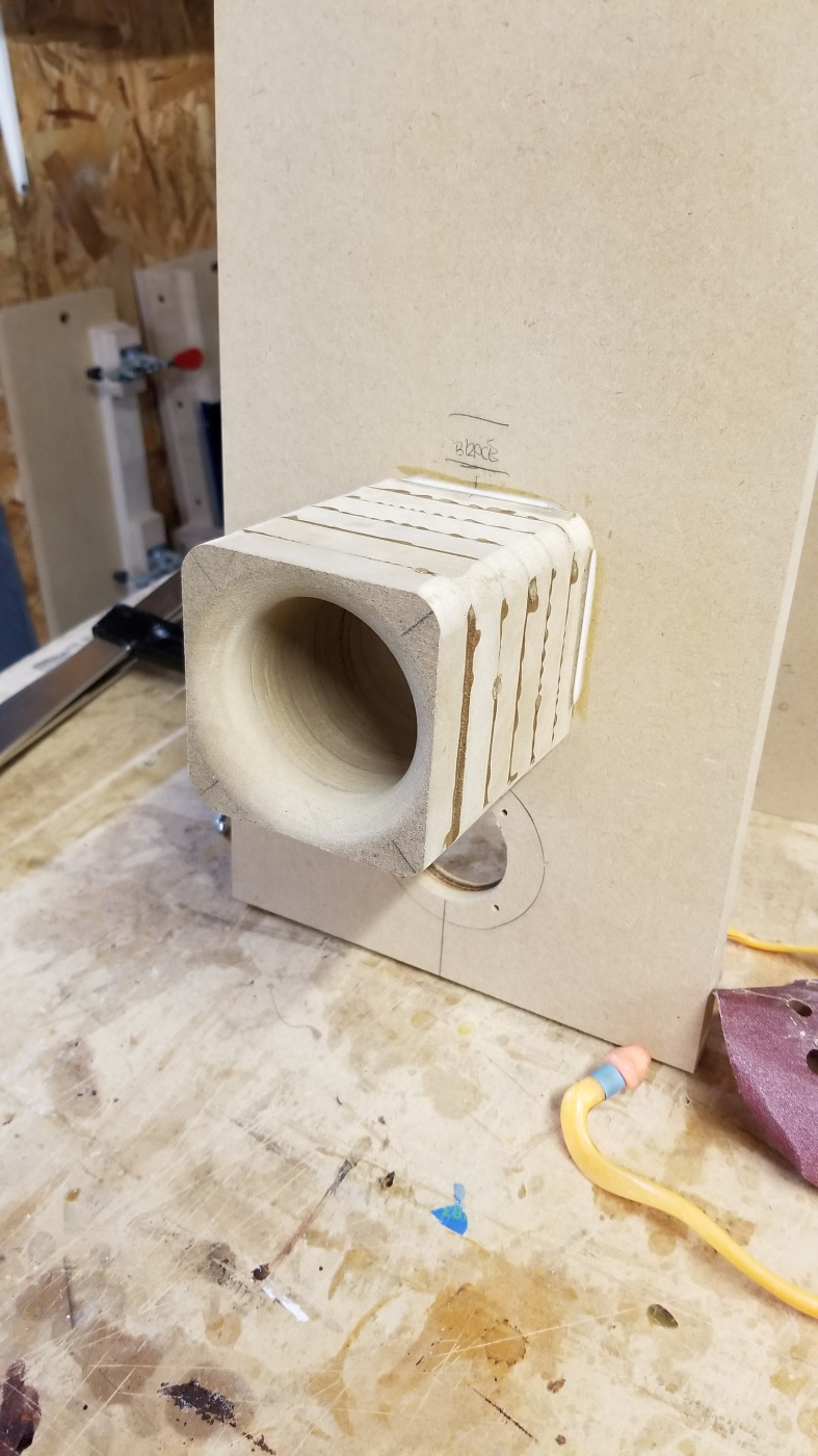
Home made port due to no 2.5" PVC available where I live. This one has me scratching my head............
Comments
That's a nearfield measurement of the woofer's cone only. It looks like that because your port output is not included. If you were to take a nearfield measurement of the port and correctly level match and splice the two together it would look very much like your WinISD sim.
Thanks Craig - I will try that today 👍
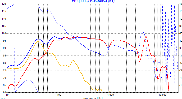
When you simulate the cabinet, it's best to plot the total SPL, as well as cone output and port output together. I'm not a WinISD expert, but it's easily done with VituixCAD, Jeff's spreadsheet, Unibox...Here's an example:
You will see the driver output looks similar to what you've shown above, it has a null near the tuning frequency where the majority of the output comes from the port. You will also notice that as frequency decreases, the port and driver output converge to the same point. This is an easy method to use to adjust the level of port and driver output when combining them, however it can be difficult to get good clean response at low frequency, especially with Omnimic. Depending on the speaker the output can start getting buried in the noise floor. Getting the levels right can be a bit challenging, fortunately this information is generally not needed for crossover design so I often don't bother.
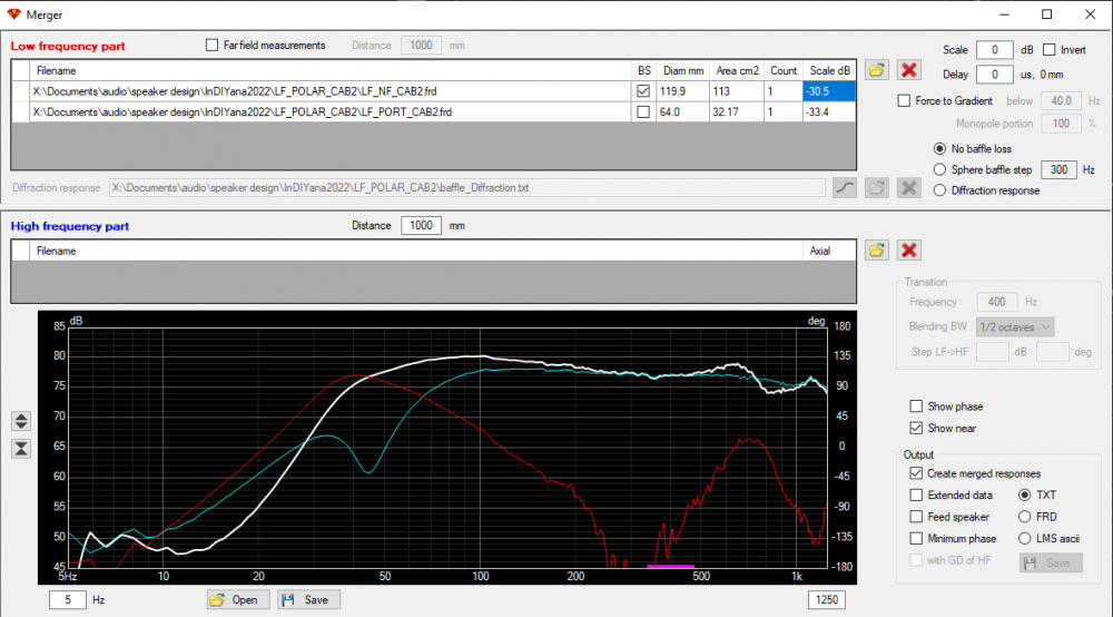
Combining the responses can be easily done within VituixCAD using the merger tool. level adjustments can be done visually as I described above, or calculated by entering surface area of driver and port, with measurements taken near field and at port exit (mic in line with baffle surface). For a simple example of this process, here's a screenshot using the InDIYana challenge speaker as an example. With just the area values entered, I found the port output was a bit lower than expected, so I applied some manual correction to bring it up where the responses converge at 10Hz.
Yeah what I said
So I took a near field measurement of the port output and used response blender to blend them together - I think I did it right... basically the speaker has very little low end to it where the modeling shows otherwise.
That doesn't look remotely right. Response blender is not the tool for this task. Blending / splicing is not the operation required, addition is. If you've done it right it should at least resemble the box model.
If you can't be bothered to use VituixCAD for this for whatever reason, you can do it right in the Omnimic software, it's just a way more painful process.
Your measurements are showing a fair bit of wonk in the 50-60Hz range as well. For nearfield measurements you should be getting fairly nice predictable lines like the screenshot I showed above. Make sure gating is disabled for near field, Omnimic "all".
Just to clarify a bit, the port response is added or summed with the woofer near field response. You can also do this in PCD or XSim. Attached is Jeff Bs "Tips" write up
Let me download Vituix and give it a try. I will take the port measurement again with no gating as well. Will the speaker wires coming out of the port cause any issues?
Only if they're buzzing.
You can add curves in Omnimic also, not sure if it uses phase data when it adds.
I took another measurement of the port with no gating and put it into Vituix like your example above and here are the results. Also did it in PCD and got pretty much the same result.
Interesting, what you've got there is way out of phase at 70Hz, so much so that you would get a better response by completely inverting the port output. Where are you placing your mic for these measurements? Like 1/4" from the woofer dustcap and then in line with the baffle surface at the port exit?
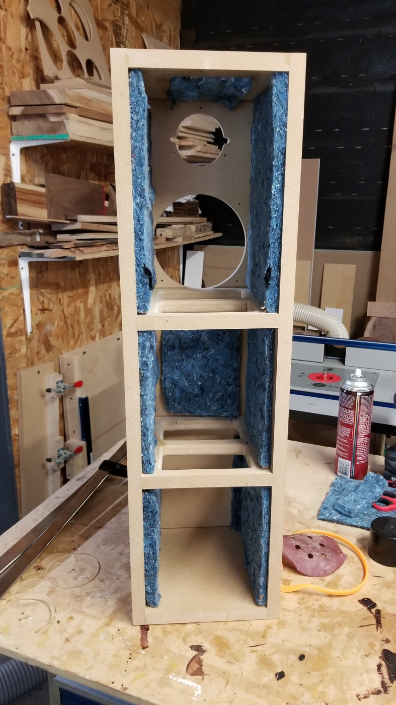
Assuming the cabinet is about 3ft tall, I'd at least start with some stuffing if you're testing with just the bits of batting stuck to the panels. 1/2 wavelength of 3ft is ~200Hz.
Yup - measured 1/4" away from woofer and in line with the baffle at the port. I will pull the woofer out tomorrow and cram some stuffing in there. Thanks for your help 👍
Is "Create merged responses" the right button?
https://kimmosaunisto.net/Software/VituixCAD/VituixCAD_help_20.html#Merger_tool
“Show phase” might be a more interesting option, to highlight that phase problem mentioned.
If I take known good measurements, and apply delay to try and reproduce something like above, it requires significant delay. Here's 8ms (2.7m) of delay included.
In Omnimic, are you sure the signal was locked in for both above measurements, that is, "check CD track "was not displayed when saving these measurements?
Playing around a bit more, I can create an equally poor result by simply taking min phase of the port response. You haven't done something silly like run the measurements through min phase extraction?
Maybe if we can see the phase of each measurement. The woofer near field looks like it flips at the knee
I am pretty sure the signal was locked in - I can take new measurements showing the phase measurement in OmniMic and post it up. I didn't do a min phase extraction either. I did go and buy some more polyfill today to play around with the stuffing, so will try that out tomorrow as well.
Here are the measurements showing the phase in OmniMic - when taking the port measurement it does say "check for correct cd track" in the response window. I filled the area between the two braces with polyfill before taking these measurements.
I also put the woofer in a different enclosure (about .7cf) and got pretty much the same results with the near field sweep.
If I takes these files and put them into PCD if I reverse the port polarity the response changes quite a bit.
This really is the problem. Above Fs (50-100Hz region) you should see port output and driver output in phase, and they're not. Omnimic software is kind of sucky, so it's having problems finding the signal from just the port output. You might want to give REW a try, you can use the Omnimic with it.
Apart from that,the problem I believe is mostly a lumpy port output. Dips at 50-60 and 100-120Hz are unexpected. Could be the fact that Omnimic hasn't given you a good measurement, but I also know some people have had problems with tower speakers with driver at the top and port at the bottom, essentially that creates a transmission line. It could also be the vertical dimension of the cabinet creating a strong reflection that is affecting port output, in both cases internal damping is the best solution (apart from a cabinet rebuild so the port is located 1/3 from the bottom for example.
What the internal height ?
Your port and cone curves look anemic and leaky, like a dual chamber effect of some sort. Double check your gasket seal on the tweeter and woofer mounting flange areas. It looks to me like you might have an air leak somewhere.
+1 on the leak. Note that omni mic is pseudo min phase so you will need to invert the phase of the port. Depending on port/ woofer sd log20 I get a reasonable but lumpy response.
Thanks for your help guys - I will check for leaks tomorrow. The internal height is 28" - I only built one box as a test box so I can always build a second one and move the port to a different spot.
Just put as much fill as you would in the completed cabinet when you take these measurements. Fill in the top will be best for the height cabinet mode. At 28", ~120Hz is 1/4 wave length, ~60Hz would be 1/8 wave length.
Omnimic / USB mic is half the problem on combining the responses, even the cheapest XLR mic with 2 channel interface would allow for perfect phase result without fussing around, but I've probably preached enough on that topic..
Inverting the response is "better" but is still not exactly right. Best solution with what you have would be to invert the phase and adjust delay to get phase alignment between driver and port output above the cabinet tuning, 50-100Hz range in this case. Tracing your response above, I get the following.
Apart from the lumpy port response, it's not terrible. I'd say it's just tuned a bit too low, looks like about 40Hz tuning where your design above was for 45Hz.
Any recommendations for a cheap mic and interface?
For a mic, Sonarworks SoundID is cheap. The el-cheapo mics are fine for frequency response, but I wouldn't put too much trust in them for distortion results. I use a Line Audio OM1, which technically isn't a "measurement mic", it has no calibration file, but are in fact individually adjusted passively to be flat, and it is a good enough quality for distortion measurement as well. It was about CAD$220 shipped if I recall, I can put you in touch with the Canadian distributor if you're interested.
The Sonarworks is available in Canada here (or try Long & Mcquade):
https://www.avshop.ca/sound-amp-pa-audio-microphones-specialty-mics/sonarworks-soundid-reference-measurement-microphone
For an interface, Behringer UMC202HD or UMC204HD are "fine" and about the cheapest interface out there. I use a Steinberg UR22mkii which I really like, it's been replaced now with a newer model UR22C which uses a USB-C connection and has an updated codec supporting 32bit audio. I used to have a "gen 1" Focusrite 2i2 and the driver support was not great so I would stay away, otherwise any half decent 2in/2out interface should be more than adequate. Check your local classifieds you can often get a good deal on a lightly used unit.
Well I pushed ahead on these and got them finished up. Wanted to try painting again after the last go didn't turn out very nice. These turned out better but not perfect by any means. Think I will stick with wood in the future")
Crossover ended up being 2nd order on the tweet and the woof with a decent in room response and only 7 parts. They sound pretty good actually for $120cdn of drivers and bass response in room is good too.
Being that they are only 30" tall I might make some bases to bring them up a few more inches or maybe just tilt them back a bit.
those turned out nice
your wouldn't need much tilt to tgt tw to your listening position
Can't go wrong with a nice white speaker, looks great dude!
Oh I like those!
Thanks 👍