Site Links
Howdy, Stranger!
It looks like you're new here. If you want to get involved, click one of these buttons!
Quick Links
Categories
In this Discussion
Who's Online (0)
Project Code Name BILC
This will be my first personal project in a long time. I was planning to get started this summer and then my son was born 5 weeks early and kind of threw things off. I’m calling this project BILC, which stands for Because It Looks Cool. This design uses four, 4” bass drivers (Dayton Audio ND105-4) per side, one 4” midrange (Peerless 830870 HDS PPB), and one 1” tweeter (Tang Band 25-1744S) so it is going to be a tower of drivers! And who doesn’t think that looks cool?
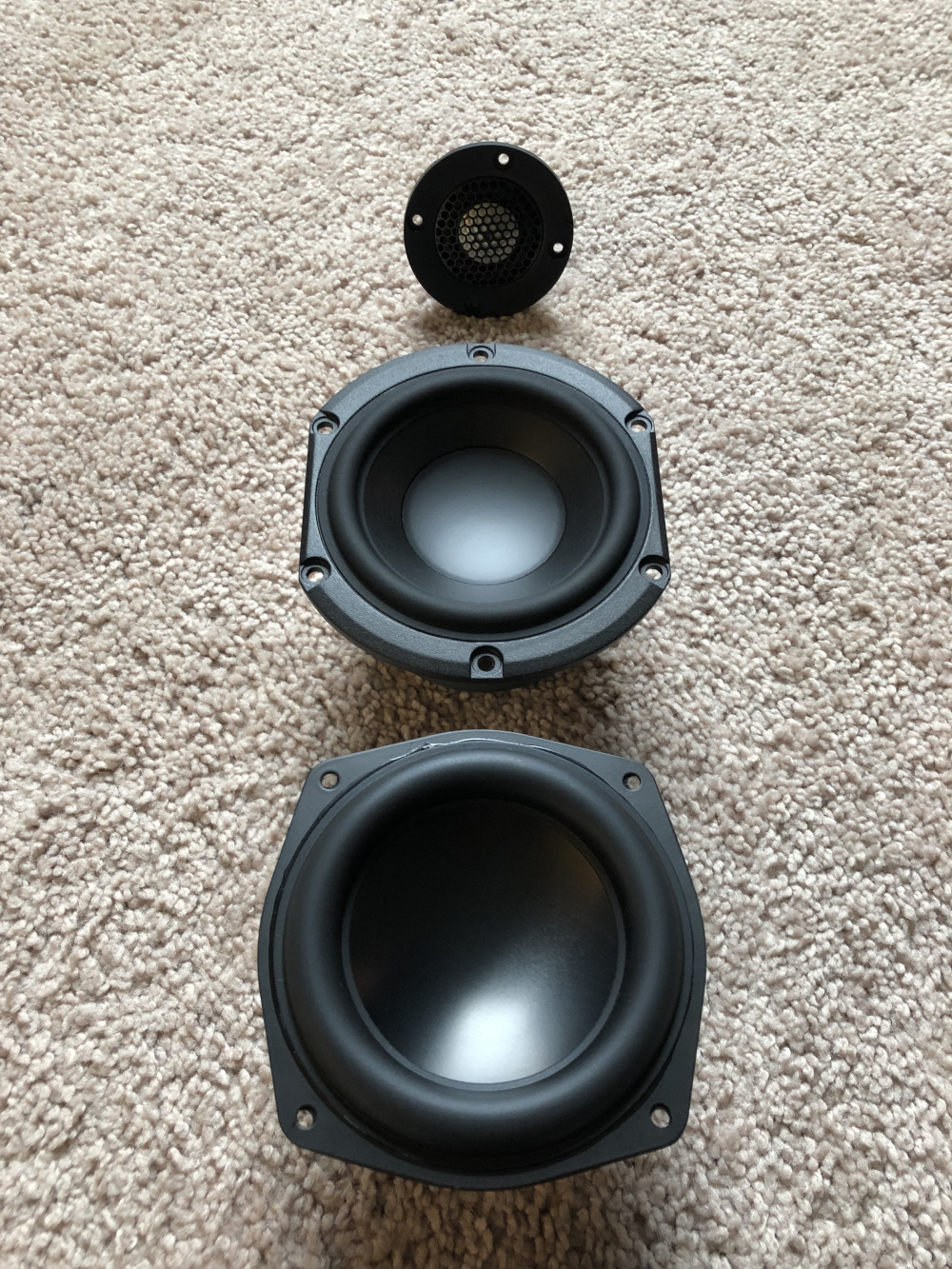
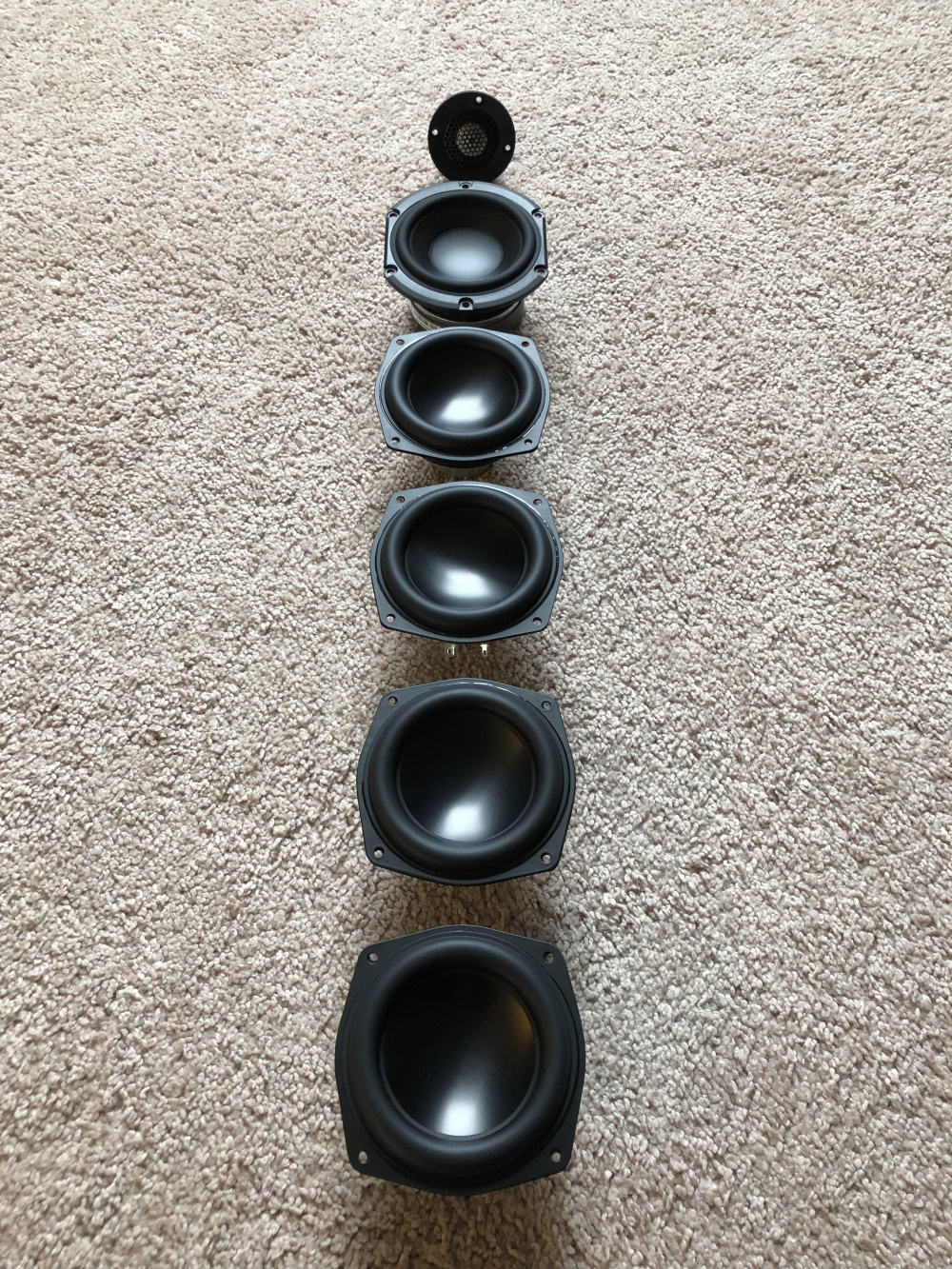


Why is it named BILC? Looking at this design rationally, There are a lot of things that tell you not to build this. While the ND105-4 can play down to 40 Hz, it still needs a decent size box (about 0.3 cu ft) to do so, which means for 4 of them we need about 1.2 cu ft. And while the four 4” drivers have almost the surface area of about a standard 8” woofer, the 8” woofer would work in about the same size box. Also, these aren’t necessarily cheap 4” woofers at a $23.29 ($93.16 per side) so looking at something like the Peerless by Tymphany 830869 8" Nomex Cone HDS Woofer at Parts Express, I could basically get the same size box, cheaper price, and most likely better distortion performance. So why did I choose to do this? BILC… and the one benefit a front firing 8” woofer can’t give you – a slim tower.
While the pictures of the drivers show the tweeter at the top, I’ve changed my mind since taking the picture and starting to plan the cabinets. I’m now going with the mid on top in the layout so it will be a MTWWWW. The cabinet external dimensions will be 44” H x 6.5” W x 14” D. This gives me about 1.53 cu ft of total internal volume available to work with before bracing, drivers, and ports. I will be taking up around 0.2 cu ft for the midrange chamber leaving about 1.3 cu ft for the bass drivers after accounting for all the bracing, port and drivers.
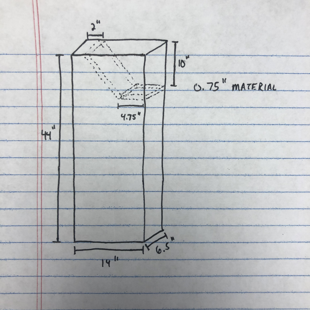

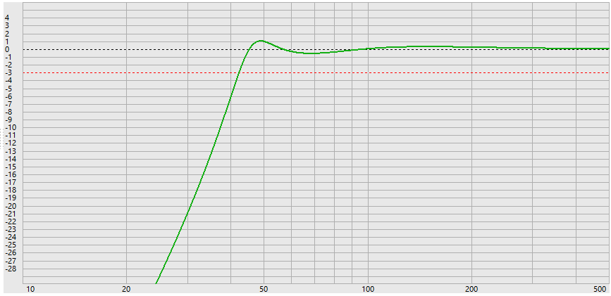
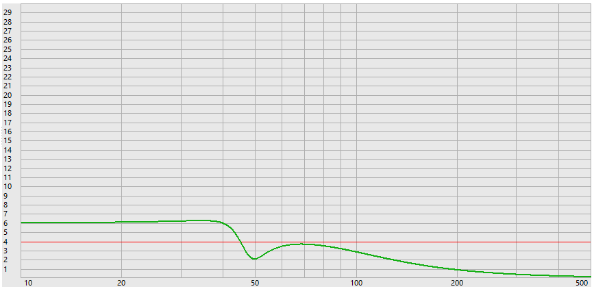
The bass enclosure will be tuned to 49 Hz, which produces and EBS alignment with an f3 of 42 Hz. I’ll be using a 3” PVC port to achieve this and keep port velocities under control up to about 50 watts of input power. One of the unique things about the ND105-4 is that while the xmax is pretty standard at 4 mm, the xmech 10 mm so there is still lots of excursion past the xmax limits. While driving something past xmax isn’t a goal, these will be used for bass only, and bass distortion is less audible than midrange distortion. This means there will likely be some useable output beyond xmax before they really start to become objectionable and also means you can really crank them without fear of damage. The woofers will be wired in a series parallel configuration so if the specs are accurate, even with full baffle step I should end up at a realistic 87 db @ 2.83 V. This is one additional benefit over going with something like the Peerless 8” I mentioned earlier. That driver after full baffle step would put me around 83 dB @ 2.83 V. Likewise, the Dayton RS225-4 would put me around 85 dB @ 2.83 V.


Comments
A 3 1/2" and 2" hole saw made quick work of cutting the braces.
Both cabinets look like this now. Midrange pieces still not cut to actual size or glued in, just laid in place for an idea of what it will look like. I left more room in the bottom for the 3" port and the crossovers.
InDIYana Event Website
Things just kept getting busier throughout the year and I didn't really have time to finish these. The paint especially became problematic and I had to spend a decent amount of time doing bondo/spot putty repairs to get something reasonable looking which was a huge time investment/set back on these. However, I finally got them wrapped up this past week and all ready to start making music.
Below is the finished product. As you can see, the measured response matches the modeled response very closely (with a small exception). Note that the final measurements were done in a different location so the low end shows more room effects in the final response. The exception is that one of the tweeters apparently is higher in output than the other. When I finally got everything assembled and listened to the crossover design, I noticed an imbalance between the two speakers and thought I had something hooked up wrong. After some measurements, one of the speakers was about 1-1.5 dB hotter in the treble. I confirmed it was not the crossover so I had to add an extra 1 Ohm of resistance to one side.
I took some distortion sweeps at 90, 95, and 100 dB as well. As you can see, the woofers are definitely the weak link. I was hoping I would get better distortion performance by using 4 of them per side but it's not as good as I would have like. Note though that a 100 dB sweep is REALLY loud. I didn't do any lower volume that would be more typical of my listening but at 80 and 85 dB it would be lower for sure. With that said, I can definitely tell that they aren't the cleanest on the bottom end. They do move some air though (about the SD of an 8" driver) so you get more actual impact than you would from a single 4" woofer. Overall they still sound good and I think most people would be happy with the bass.
Nice outriggers and stripe. Is that one piece for outriggers?
No, a plate that large got very expensive so I cut it out of a strip of 3" wide aluminum on a miter saw and then glued it on the MDF layer.
did you use trim rings or rear mounted the drivers? It's looking very neat.
Those are nice looking. The outriggers add a touch of pizzazz too. Wait, the strip near the top is alum?
Beautiful they are.
TomZ
**ZARBO AUDIO ** https://www.youtube.com/channel/UCEZUyvobRaFQSTl6NdOwgxQ
They are trim rings. Just a deep recess on the drivers. I’ve probably got some other in progress pictures on my phone o can post.
Yeah, that is also a strip of aluminum.
Probably all out of order like the first batch but this goes back to like June for the build progress.

ll
Love the outriggers. Love the trim rings - printed? Teak baffle?
Man, you're projects need to be in magazines somewhere. Simply stunning!
David
Nicely done, I would never have thought of gluing the aluminum to mdf for the outriggers, my dumb ass would have just bought 1/2" thick aluminum, but seriously, these look good nice design.
Thank you. The trim ring are 3D printed but could easily be made with a router as well. The veneer is Santos rosewood.
Haha! I thought about it. 1/2” would be a bigger pain for me to do on my equipment and I’d have to buy a tap set for the spikes. I actually first had this idea of gluing to something else on the Juggernauts. I had some 1/4” aluminum I had bought which would work fine for something the weight of these but the Juggernauts weighed about 100 lbs finished so I was worried it would buckle and had to come up with something else.
Super nice job👍🏻 Love the rosewood and the trim rings tying the drivers together. How are they held on?
Just a snug fit. I might regret that later if the plywood decides to expand too much but I guess we'll see.
Gorgeous package!
Any chance you still have the files for the trim rings?
If they come loose how about gluing some small neo magnets in the four holes on the underside of the trim ring? I suspect they could be aligned close enough to the woofer frame edges or mounting screws to hold the trim in place.
... and super nice build.