Showing off test gear sounds like a great thread. I use a mix of ARTA, Omnimic, DATS (the new fangled one with the extruded housing is pretty damn nice build quality compared to my original WT3 piece of shit), and LIMP.
When using ARTA, I use a Soundblaster something or other (desktop style, forget what model it is) out to a Behringer mixer. I use the same Dayton APA150 for ARTA and Omnimic. I am currently contemplating adding an additional APA150 (actually the 'Franklin Audio' buyout model) and making a dedicated large signal test rig for ARTA/LIMP.
I like the ease of the Dayton test stuff, but the benefits of 2-channel measurement are hard to deny so my initial design measurements are through ARTA, the quick stuff during verification is done via Omnimic. Works for me.
You can also use the Omnimic in ARTA, as long as you are OK with single channel measurements. I had to remove some stuff in the calibration file Omnimic ships with and rename the file extension. It seems to work just fine.
Got a little more done last night. Heaters are all wired - my least favorite part. Most of the B+ section is ready for when I mount the output transformers.
Considering how close the audio inputs are to the power switch, I don't really want to run 120v AC up there to the switch. I've decided to use a small DC supply & a relay board near the back and run a low voltage DC line to the front.
None of the surplus relays I had in the drawer were quite what I was looking for, so Amazon will be dropping off more parts on Saturday. I though this little PS module looked like it might do the trick. It's tiny - 35mm x 21 x 16
You are correct! 220pf//6.8K off the 16 ohm tap feeding back to the cathode of the gain stage. This one uses a current source (an LM334) on the cathodes of the splitters.
Getting really close to firing this thing up! Just need to finish the input connections and wire up the speaker side of the output transformers. I had already breadboarded a simple supply with a small Stancor 6.3v transformer, 1N4007, & a 1K uF cap in case the relay circuit parts got delayed. But they arrived right on time & this little power supply module is tiny and the voltage is rock steady. The pins don't quite match a standard pc board, so I made a little mount out of a chunk of surplus fiberglass board and used the transformer bolts to hold it in place. Thank God for zip ties!
As I was getting close to buttoning this project up, I realized I didn't know for sure if the output transformers were actually still good. This amp was an ebay buy years ago and was in horrible physical shape. The resistance readings of the windings are so low that it's hard to tell, but nothing looked like it was shorted. I hooked up the signal generator to the primaries and the scope to the secondaries and signals looked good, so I forged ahead.
I got everything except the new remote power circuit wired up. I powered up the output section, one side at a time, like the manual suggested. B+ is a little higher than I remembered, but I was able to get a stable bias on each tube. OK - tested some used 12AU7s and dropped a decent trio in the amp for a quick test flight with real speakers. Sounded really dull - no high end. The bias had dropped to about 1/3 of where it should be. I could not get it to come up to spec, even with the pots on the board dimed. But - I was using a 5U4G instead of a 5AR4 for testing. Didn't want to arch over a nice vintage 5AR4 due to a stupid wiring error. But everything else seemed fine so I dropped in the appropriate rectifier tube and it fell into line. I heard a little frying noise while I was resetting the bias. It sounded like a 12au7 might have a dirty pin - they were really old, used tubes. It settled down and the bias fell into line. Music sounded MUCH better. Listened for about 15 minutes. Then I decided to see of the new power transformer was warm - nope. Just a little above ambient. But the new can cap that had been sitting on the shelf for about a decade was HOT! Too hot to touch - my infrared thermometer read 150 degrees! That explains the frying noise. So now I'll be pulling that out, ordering a new one, and triple checking all voltages again.
Yep - a standard CE Manufacturing 4 section cap. I saw a video from BlueGlow Electronics where he found a bad section in a brand new one, so I'm hoping that's all this is. Since mine had been sitting so long, I probably should have reformed it on the variable HV power supply before hitting it with the full B+. Lesson learned the hard way.
The replacement quad cap finally showed up last night. I ordered it on the 16th through Amazon and it turns out it came from one of Antique Electronics Supply's alter ego companies, Amplified Parts. I didn't order from AES (Tubesandmore.com) directly because I remembered they take forever to ship stuff. Lesson learned - I'll use Tube Depot or The Tube Store next time.
I checked all my solder joints around the amp and measured the DC resistance of the output transformers again and checked for any shorts to ground before installing this new cap. Nothing found - in goes the cap with temporary solder joints. I brought the amp up slowly on the variac - rectifier kicked in around 60v - current draw didn't move the crusty meter on the variac much and voltages on the B+ and output tubes looked normal. As I got above 100v - smoke! I powered down quickly and saw the rubber boot of the gator clip touching the 2.2K/3W dropping resistor was smoldering. That line leads to the new driver board and it shouldn't be pulling that much current - maybe 25ma across that resistor.
Finally - it's playing music and not making smoke or overheating. Turned out to be just the bad NOS quad cap and a bad solder joint on one of the EL34 sockets that feeds the grid.
It sounds really good - much better than either of my other two ST-70s. Maybe not a fair fight since the only original parts on this one are the output transformers, the choke, and the basic chassis. I'm running a 5U4GB to keep the B+ down a little. I have new production 12AU7s in the front end. I got those from Kornbread in our little tube trade a few weeks ago and they're sounding good.
Excellent build. Good to see you solved the power supply problem. I was wondering how you were going to route the RCA input cables past the power transformer and choke. Nice solution. So, you looped it up and around the edge to keep the cable as far away as possible.
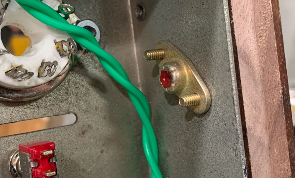
Bill - I just realized I didn't respond about the input cables. Yep - I used some surplus mini coaxial cable and it runs along the bottom plate once it's slid into place. I wire-tied them to some solder lugs bolted onto the sides via whatever you call these - nutplates?
Comments
Maybe we need a "show your test gear" thread.
Very nice Tom.
I'm in for that!
Showing off test gear sounds like a great thread. I use a mix of ARTA, Omnimic, DATS (the new fangled one with the extruded housing is pretty damn nice build quality compared to my original WT3 piece of shit), and LIMP.
When using ARTA, I use a Soundblaster something or other (desktop style, forget what model it is) out to a Behringer mixer. I use the same Dayton APA150 for ARTA and Omnimic. I am currently contemplating adding an additional APA150 (actually the 'Franklin Audio' buyout model) and making a dedicated large signal test rig for ARTA/LIMP.
I like the ease of the Dayton test stuff, but the benefits of 2-channel measurement are hard to deny so my initial design measurements are through ARTA, the quick stuff during verification is done via Omnimic. Works for me.
You can also use the Omnimic in ARTA, as long as you are OK with single channel measurements. I had to remove some stuff in the calibration file Omnimic ships with and rename the file extension. It seems to work just fine.
I was thinking more about my oscilloscopes, bench top power supplies, Flukes, tube tester, etc.
That too, I have a Fluke DMM and a Der EE LCR I use pretty regular - and also some other test instruments not at all related to building speakers.
Got a little more done last night. Heaters are all wired - my least favorite part. Most of the B+ section is ready for when I mount the output transformers.
Considering how close the audio inputs are to the power switch, I don't really want to run 120v AC up there to the switch. I've decided to use a small DC supply & a relay board near the back and run a low voltage DC line to the front.
None of the surplus relays I had in the drawer were quite what I was looking for, so Amazon will be dropping off more parts on Saturday. I though this little PS module looked like it might do the trick. It's tiny - 35mm x 21 x 16
Good thinking!
I see some silver mica caps. Are they in the NFB circuit?
You are correct! 220pf//6.8K off the 16 ohm tap feeding back to the cathode of the gain stage. This one uses a current source (an LM334) on the cathodes of the splitters.
Getting really close to firing this thing up! Just need to finish the input connections and wire up the speaker side of the output transformers. I had already breadboarded a simple supply with a small Stancor 6.3v transformer, 1N4007, & a 1K uF cap in case the relay circuit parts got delayed. But they arrived right on time & this little power supply module is tiny and the voltage is rock steady. The pins don't quite match a standard pc board, so I made a little mount out of a chunk of surplus fiberglass board and used the transformer bolts to hold it in place. Thank God for zip ties!
You're going to have that going before I'm through with mine.
Sorry - this post is a little long.
As I was getting close to buttoning this project up, I realized I didn't know for sure if the output transformers were actually still good. This amp was an ebay buy years ago and was in horrible physical shape. The resistance readings of the windings are so low that it's hard to tell, but nothing looked like it was shorted. I hooked up the signal generator to the primaries and the scope to the secondaries and signals looked good, so I forged ahead.
I got everything except the new remote power circuit wired up. I powered up the output section, one side at a time, like the manual suggested. B+ is a little higher than I remembered, but I was able to get a stable bias on each tube. OK - tested some used 12AU7s and dropped a decent trio in the amp for a quick test flight with real speakers. Sounded really dull - no high end. The bias had dropped to about 1/3 of where it should be. I could not get it to come up to spec, even with the pots on the board dimed. But - I was using a 5U4G instead of a 5AR4 for testing. Didn't want to arch over a nice vintage 5AR4 due to a stupid wiring error. But everything else seemed fine so I dropped in the appropriate rectifier tube and it fell into line. I heard a little frying noise while I was resetting the bias. It sounded like a 12au7 might have a dirty pin - they were really old, used tubes. It settled down and the bias fell into line. Music sounded MUCH better. Listened for about 15 minutes. Then I decided to see of the new power transformer was warm - nope. Just a little above ambient. But the new can cap that had been sitting on the shelf for about a decade was HOT! Too hot to touch - my infrared thermometer read 150 degrees! That explains the frying noise. So now I'll be pulling that out, ordering a new one, and triple checking all voltages again.
Multi-section electrolytic?
Yep - a standard CE Manufacturing 4 section cap. I saw a video from BlueGlow Electronics where he found a bad section in a brand new one, so I'm hoping that's all this is. Since mine had been sitting so long, I probably should have reformed it on the variable HV power supply before hitting it with the full B+. Lesson learned the hard way.
Looks like this leaked a tiny bit of the Magic Fluid. Hard to see in a photo, but you can wiggle the lug and see the fluid at the base of it.
Luckily it didn't spew that crap all over. It's a pain to clean up.
The replacement quad cap finally showed up last night. I ordered it on the 16th through Amazon and it turns out it came from one of Antique Electronics Supply's alter ego companies, Amplified Parts. I didn't order from AES (Tubesandmore.com) directly because I remembered they take forever to ship stuff. Lesson learned - I'll use Tube Depot or The Tube Store next time.
I checked all my solder joints around the amp and measured the DC resistance of the output transformers again and checked for any shorts to ground before installing this new cap. Nothing found - in goes the cap with temporary solder joints. I brought the amp up slowly on the variac - rectifier kicked in around 60v - current draw didn't move the crusty meter on the variac much and voltages on the B+ and output tubes looked normal. As I got above 100v - smoke! I powered down quickly and saw the rubber boot of the gator clip touching the 2.2K/3W dropping resistor was smoldering. That line leads to the new driver board and it shouldn't be pulling that much current - maybe 25ma across that resistor.
I know that smell.
Finally - it's playing music and not making smoke or overheating. Turned out to be just the bad NOS quad cap and a bad solder joint on one of the EL34 sockets that feeds the grid.
It sounds really good - much better than either of my other two ST-70s. Maybe not a fair fight since the only original parts on this one are the output transformers, the choke, and the basic chassis. I'm running a 5U4GB to keep the B+ down a little. I have new production 12AU7s in the front end. I got those from Kornbread in our little tube trade a few weeks ago and they're sounding good.")
It's a keeper!
Excellent build. Good to see you solved the power supply problem. I was wondering how you were going to route the RCA input cables past the power transformer and choke. Nice solution. So, you looped it up and around the edge to keep the cable as far away as possible.
Bill - I just realized I didn't respond about the input cables. Yep - I used some surplus mini coaxial cable and it runs along the bottom plate once it's slid into place. I wire-tied them to some solder lugs bolted onto the sides via whatever you call these - nutplates?