Agreed. This is one on the reasons that I have not purchased a large 1.5" radius roundover bit yet. I have a Bosch 1617 router (2.25HP) mounted in a Bosch RA1181 table. I am somewhat nervous about trying use a bit this large.
@PWRRYD said:
Or just use those huge cardboard tubes I gave you. Those will give you about a 2.5" radius. A bit more work to blend them in but totally worth it.
"Diffraction?!?! We got no stinkin diffraction here!"
Interesting. When I get Craig's 2.5" radius tubes mounted on the my 9x39" baffles, I'll run up another set of CQ76B polars and post them. Then we can compare 3/4" radius, 2.5" radius, and full IEC baffle diffraction signatures.
I cut Craig's 5" diameter tubes into quarter sections and then affixed them with blue masking tape to the front edges of my 9x39" baffles. Then I ran up another set of polars. As promised, below are some graphs comparing 0.75" and 2.50" roundovers to the large 52.5x64" IEC test baffle.
First graph is 0-90 degrees with 2.5" roundovers (baffle width is now 14" instead of 9"):
The next graph is an on-axis overlay comparison of the IEC baffle verses the 9" x 39" 0.75" roundover baffle verses the 14"x39" 2.50" roundover baffle. Note that the graphs are very similar above 4kHz. However, from 700 to 7000Hz, they are significantly different. The IEC is plus or minus 1dB over this range. The 0.75 baffle is plus or minus 2.5dB. And the 2.50 baffle is plus or minus 1.75dB.
Finally, here is an overlay comparison of the same three baffles, but this time at 45 degrees off-axis only. The curves are very similar. The IEC baffle has a little bit more bass extension, as would be expected. Will the huge suck out at 16kHz be audible? I suppose, if you were sitting off axis, and one speaker was pointing directly at you while the other was at 45 degrees, the soundstage might completely collapse. I'll have to scope this out when I get both speakers done.
If you decide to go with wide radius corners/sides you could look at Tape Ease Supply in Maribel WI, halfway between Green Bay and Manitowoc. They have MDF quarter rounds in 2, 3, 4 and 6 inch radiuses. Here's a link to their "MDF L Quarter Rounds". https://tapeease.com/cabinet1.htm
@4thtry said:
I cut Craig's 5" diameter tubes into quarter sections and then affixed them with blue masking tape....
..Will the huge suck out at 16kHz be audible?
Your speakers usually look great, but I don't like the look of the cardboard and blue tape. (just kidding)
Not only does the suckout not really come into play until about 45 degrees, that's above a lot of our hearing ("our" meaning males over 40).
After I take a quasi-IB measurement of my tweeter (eg. An appropriately large IEC baffle, measured at 31.6cm so you are effectively in the half space; then post process with -10dB to calculate the 1m response)
Sometimes I use the VituixCAD2 Diffraction tool to simulate for the frequency response; to choose the ideal baffle size/shape or position of which to place my tweeter.
It’s in the Tools menu…
One loads up the their quasi-IB measurements in the “Half space response” section; and then move your driver around your baffle, change the dimensions of your baffle, change the round-over size, move the mic position. All on the fly.
Then click on Export full space response; and ensure Directivity is selected, with your option of 10 degree step size and vertical plane. If you “Feed speaker; it will directly put the simulated measurements into the selected driver in the Drivers window. If you don’t “Feed Speaker” you get to save all the off axis responses into a folder, and you can later view them in a program like REW or SoundEasy.
What you may find is that if roundover or chamfers start as close as possible to the tweeter, the response may improve. So for instance in the above study, for a speaker with a 2.5” roudover; to get an improvement over the 0.75” roundover, you want to keep a 9” wide baffle, not extend it to 14”.
A picture is attached below- roundover starting at the green, not the blue,
Caveat: it really depends on the particularly tweeter; simulation is based a circular or rectangular transducer with a perfectly flat piston. So it is not 100% accurate. But it will get you to within +/- 1dB ballpark.
Thank you, tktran! I simulated a 9" baffle with 2.5" roundovers in VituixCAD and noticed a significant reduction in ripple from 700 to 4000Hz. And if I raise the tweeter 2 inches higher on the baffle, so that the 2.5" roundover starts very close to the top edge of the tweeter as well, then the ripple flattens out completely. Amazing. I think I need to pay much more attention to the models before cutting and drilling holes.
@Ed_Perkins said:
If you decide to go with wide radius corners/sides you could look at Tape Ease Supply in Maribel WI, halfway between Green Bay and Manitowoc. They have MDF quarter rounds in 2, 3, 4 and 6 inch radiuses. Here's a link to their "MDF L Quarter Rounds". https://tapeease.com/cabinet1.htm
Thanks, Ed. I'll have to give these a try on my next build. The 2 or 3" look like the best options, shipped in 48.5" sections.
@4thtry said:
I cut Craig's 5" diameter tubes into quarter sections and then affixed them with blue masking tape....
..Will the huge suck out at 16kHz be audible?
Your speakers usually look great, but I don't like the look of the cardboard and blue tape. (just kidding)
Not only does the suckout not really come into play until about 45 degrees, that's above a lot of our hearing ("our" meaning males over 40).
Thanks, David. Gives them more of an industrial type look, which, for me, is OK. This gives me greater freedom to make modifications on the fly, because I don't have to worry about messing up the finish.
The newer quarter-rounds have 3/8" edges that make assembly/glue up easier. I use a couple of adjustable straps with ratchets to tighten everything up.
@tktran said:
After I take a quasi-IB measurement of my tweeter (eg. An appropriately large IEC baffle, measured at 31.6cm so you are effectively in the half space; then post process with -10dB to calculate the 1m response)
Sometimes I use the VituixCAD2 Diffraction tool to simulate for the frequency response; to choose the ideal baffle size/shape or position of which to place my tweeter.
It’s in the Tools menu…
One loads up the their quasi-IB measurements in the “Half space response” section; and then move your driver around your baffle, change the dimensions of your baffle, change the round-over size, move the mic position. All on the fly.
Then click on Export full space response; and ensure Directivity is selected, with your option of 10 degree step size and vertical plane. If you “Feed speaker; it will directly put the simulated measurements into the selected driver in the Drivers window. If you don’t “Feed Speaker” you get to save all the off axis responses into a folder, and you can later view them in a program like REW or SoundEasy.
What you may find is that if roundover or chamfers start as close as possible to the tweeter, the response may improve. So for instance in the above study, for a speaker with a 2.5” roudover; to get an improvement over the 0.75” roundover, you want to keep a 9” wide baffle, not extend it to 14”.
A picture is attached below- roundover starting at the green, not the blue,
Caveat: it really depends on the particularly tweeter; simulation is based a circular or rectangular transducer with a perfectly flat piston. So it is not 100% accurate. But it will get you to within +/- 1dB ballpark.
I decided to take your recommendation and move my roundovers as close as possible to the tweeter. And the result was very successful (see graphs below)! Not as good as the IEC test baffle, but much better than either the 9x39 3/4" roundover baffle or the 14x39 2.5" roundover baffle. I drew layout lines on the baffle (see pic) and then, using a very fluid type circular motion, belt sanded the edge down to the layout lines. The roundover varies continuously from a 3/4" radius near the woofer to a much larger 2.25" radius near and around the top edges. It is kind of like a facet but with a roundover instead of a flat 45 degree angle surface. I used 3/4", 1.5" and 2.0" roundover sanding templates to remove any imperfections left by the belt sander.
Here is the CQ76B mounted on the 2.25" radius tapered baffle, 0-90 degrees. It still peaks up a little at about 1.4kHz, but the 2-4kHz region is much smoother:
Here is a 1 meter on-axis comparison of the CQ76B mounted on all 4 tested baffles. Curves have been offset by 3dB for clarity. The IEC baffle looks the best. I would give 2nd place to the 9" wide 2.25" radius tapered baffle. 3rd place goes to the 14" wide 2.5" radius baffle. And last place to the 9" wide 3/4" radius baffle.
These guys had method to their madness. I guess now the trade secret is out!
amazing hey?!
Thanks for sharing the data here for all of us the learn from.
Every Christmas I send Kimmo a small donation for this amazing piece of free software. It has totally changed the way I’ve worked. What a great time to be alive! I bet a heap of speaker designers who have now passed would have loved to have access to such a great tool.
Btw, how deep is your tweeter mount?
Interestingly, did you take any wide angle measurements ie. >90 degrees?
Well I like good speakers as much is the next guy, but I really don’t want to build a snowman. I’m still scratching my head about how to use a spherical or tear shaped enclosure and still make something that looks good.
Remember those eggs shaped and oval shaped speakers, eg KEF Klegg or Blueroom minipod. It’s a tough sell when you have to explain to customers (spouse or friend) why ‘that thing’ looks so weird.
Like those bubble shaped cars like Mazda 121 or Chrysler PT cruiser? Looked good; for about the first 10 seconds.
Can't disagree which is why I just ordered some 22.5* chamfer router bits so I can create a curved baffle edge in steps - I plan to make separate boxes for the 3 way drivers and stack them on the next project.
If you made speakers using medicine balls, basketballs and soccer balls then baseballs stacked-up you could sell them to sports athletes I suppose . . . gotta know your market.
o Baffle edges are 90*
o Cut a 22.5* chamfer [in the router] upon a strip of material about 1" in width; the other side/edge at 90* [table-saw]
o Then cut another strip like the 1st one and then another 3 strips like the 1st.
o Lay them upon strips of painters tape with the 22.5* edges adjoining the 90* edges
o Apply glue to the mating edges
o Pick up the tape from one end and pull the adjoining surfaces together into an arc culminating into a 90* curve and hold it there until it sets up.
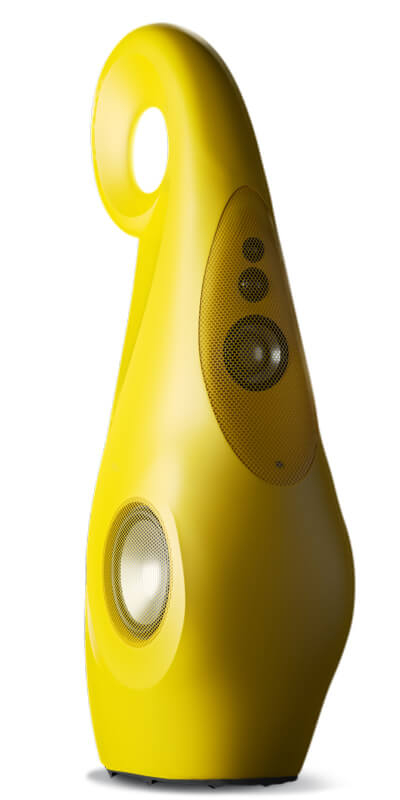
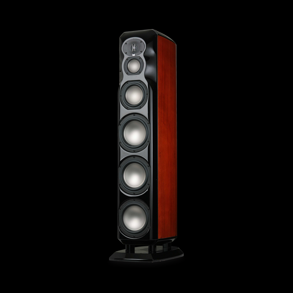
Those Vivid Audio speakers are hideous, maybe its the yellow - but I doubt it. The Revel are beautiful.
Diffraction control is important, but roundovers only go so far unless you get pretty large radius. That's one of the reasons Revel/Infinity use the shallow waveguides on their tweeters along with edge treatment.
@tktran said:
Btw, how deep is your tweeter mount?
Interestingly, did you take any wide angle measurements ie. >90 degrees?
Thanks, tktran! The CQ76B is flush mounted to all baffle surfaces with a 3/16" recess. The pleated diaphram inside the tweeter appears to be recessed about 3/16" behind the faceplate and has small 45 degree angle chamfers all around the opening.
I also did full 180 degree spin measurements for both the tweeters and woofers in my design. But I'll hold off discussion of that and start another thread later, because this thread is just about the CQ76B and how it measures.
o Baffle edges are 90*
o Cut a 22.5* chamfer [in the router] upon a strip of material about 1" in width; the other side/edge at 90* [table-saw]
o Then cut another strip like the 1st one and then another 3 strips like the 1st.
o Lay them upon strips of painters tape with the 22.5* edges adjoining the 90* edges
o Apply glue to the mating edges
o Pick up the tape from one end and pull the adjoining surfaces together into an arc culminating into a 90* curve and hold it there until it sets up.
Comments
Make sure you have a big router too.
Yeah, that too, preferably in a table.
InDIYana Event Website
Agreed. This is one on the reasons that I have not purchased a large 1.5" radius roundover bit yet. I have a Bosch 1617 router (2.25HP) mounted in a Bosch RA1181 table. I am somewhat nervous about trying use a bit this large.
Or just use those huge cardboard tubes I gave you. Those will give you about a 2.5" radius. A bit more work to blend them in but totally worth it.
"Diffraction?!?! We got no stinkin diffraction here!"
That sounds like a plan. Will do.
Don't fear the larger bits, just use light cuts and multiple passes.
My 1-1/2" bit is scary, vibrates like an old car doing 70. I won't use it. The 1-1/4" works just fine, though.
This is the best I could do without a waveguided tweeter.
Unfortunately with a 1.5” round over, it just reduces the peak/dip.
Small roundover/bevel Study:
https://www.diyaudio.com/community/threads/roundover-vs-45-chamfer-vs-double-22-5-chamfer-edge-treatments-for-tweeter-diffraction.384218/
Interesting. When I get Craig's 2.5" radius tubes mounted on the my 9x39" baffles, I'll run up another set of CQ76B polars and post them. Then we can compare 3/4" radius, 2.5" radius, and full IEC baffle diffraction signatures.
I cut Craig's 5" diameter tubes into quarter sections and then affixed them with blue masking tape to the front edges of my 9x39" baffles. Then I ran up another set of polars. As promised, below are some graphs comparing 0.75" and 2.50" roundovers to the large 52.5x64" IEC test baffle.
First graph is 0-90 degrees with 2.5" roundovers (baffle width is now 14" instead of 9"):
The next graph is an on-axis overlay comparison of the IEC baffle verses the 9" x 39" 0.75" roundover baffle verses the 14"x39" 2.50" roundover baffle. Note that the graphs are very similar above 4kHz. However, from 700 to 7000Hz, they are significantly different. The IEC is plus or minus 1dB over this range. The 0.75 baffle is plus or minus 2.5dB. And the 2.50 baffle is plus or minus 1.75dB.
Finally, here is an overlay comparison of the same three baffles, but this time at 45 degrees off-axis only. The curves are very similar. The IEC baffle has a little bit more bass extension, as would be expected. Will the huge suck out at 16kHz be audible? I suppose, if you were sitting off axis, and one speaker was pointing directly at you while the other was at 45 degrees, the soundstage might completely collapse. I'll have to scope this out when I get both speakers done.
If you decide to go with wide radius corners/sides you could look at Tape Ease Supply in Maribel WI, halfway between Green Bay and Manitowoc. They have MDF quarter rounds in 2, 3, 4 and 6 inch radiuses. Here's a link to their "MDF L Quarter Rounds". https://tapeease.com/cabinet1.htm
Your speakers usually look great, but I don't like the look of the cardboard and blue tape.

 (just kidding)
Not only does the suckout not really come into play until about 45 degrees, that's above a lot of our hearing ("our" meaning males over 40).
After I take a quasi-IB measurement of my tweeter (eg. An appropriately large IEC baffle, measured at 31.6cm so you are effectively in the half space; then post process with -10dB to calculate the 1m response)
Sometimes I use the VituixCAD2 Diffraction tool to simulate for the frequency response; to choose the ideal baffle size/shape or position of which to place my tweeter.
It’s in the Tools menu…
One loads up the their quasi-IB measurements in the “Half space response” section; and then move your driver around your baffle, change the dimensions of your baffle, change the round-over size, move the mic position. All on the fly.
Then click on Export full space response; and ensure Directivity is selected, with your option of 10 degree step size and vertical plane. If you “Feed speaker; it will directly put the simulated measurements into the selected driver in the Drivers window. If you don’t “Feed Speaker” you get to save all the off axis responses into a folder, and you can later view them in a program like REW or SoundEasy.
Totally worth it before you cut another baffle.
Reference:
https://kimmosaunisto.net/Software/VituixCAD/VituixCAD_help_20.html#Diffraction_tool
Spoiler alert:
What you may find is that if roundover or chamfers start as close as possible to the tweeter, the response may improve. So for instance in the above study, for a speaker with a 2.5” roudover; to get an improvement over the 0.75” roundover, you want to keep a 9” wide baffle, not extend it to 14”.
A picture is attached below- roundover starting at the green, not the blue,
Caveat: it really depends on the particularly tweeter; simulation is based a circular or rectangular transducer with a perfectly flat piston. So it is not 100% accurate. But it will get you to within +/- 1dB ballpark.
Thank you, tktran! I simulated a 9" baffle with 2.5" roundovers in VituixCAD and noticed a significant reduction in ripple from 700 to 4000Hz. And if I raise the tweeter 2 inches higher on the baffle, so that the 2.5" roundover starts very close to the top edge of the tweeter as well, then the ripple flattens out completely. Amazing. I think I need to pay much more attention to the models before cutting and drilling holes.
Thanks, Ed. I'll have to give these a try on my next build. The 2 or 3" look like the best options, shipped in 48.5" sections.
Thanks, David. Gives them more of an industrial type look, which, for me, is OK. This gives me greater freedom to make modifications on the fly, because I don't have to worry about messing up the finish.
I dug mine out. Almost 20 yrs old. I gotta stop saving stuff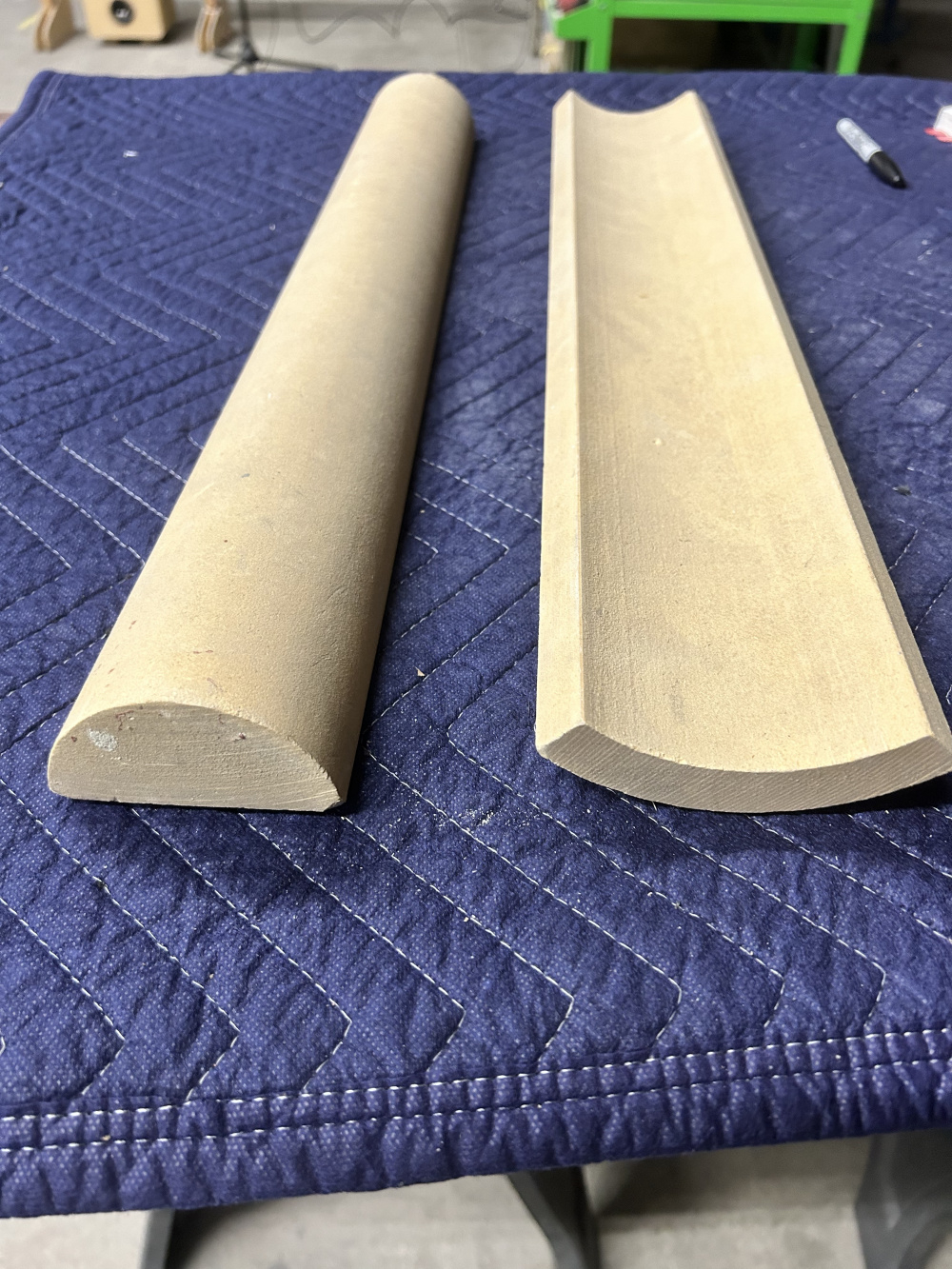
stuff.
https://www.jfcomponents.com/
The newer quarter-rounds have 3/8" edges that make assembly/glue up easier. I use a couple of adjustable straps with ratchets to tighten everything up.
I decided to take your recommendation and move my roundovers as close as possible to the tweeter. And the result was very successful (see graphs below)! Not as good as the IEC test baffle, but much better than either the 9x39 3/4" roundover baffle or the 14x39 2.5" roundover baffle. I drew layout lines on the baffle (see pic) and then, using a very fluid type circular motion, belt sanded the edge down to the layout lines. The roundover varies continuously from a 3/4" radius near the woofer to a much larger 2.25" radius near and around the top edges. It is kind of like a facet but with a roundover instead of a flat 45 degree angle surface. I used 3/4", 1.5" and 2.0" roundover sanding templates to remove any imperfections left by the belt sander.
Here is the CQ76B mounted on the 2.25" radius tapered baffle, 0-90 degrees. It still peaks up a little at about 1.4kHz, but the 2-4kHz region is much smoother:
Here is a 1 meter on-axis comparison of the CQ76B mounted on all 4 tested baffles. Curves have been offset by 3dB for clarity. The IEC baffle looks the best. I would give 2nd place to the 9" wide 2.25" radius tapered baffle. 3rd place goes to the 14" wide 2.5" radius baffle. And last place to the 9" wide 3/4" radius baffle.
And at 45 degrees:
These guys had method to their madness. I guess now the trade secret is out!
amazing hey?!
Thanks for sharing the data here for all of us the learn from.
Every Christmas I send Kimmo a small donation for this amazing piece of free software. It has totally changed the way I’ve worked. What a great time to be alive! I bet a heap of speaker designers who have now passed would have loved to have access to such a great tool.
Btw, how deep is your tweeter mount?
Interestingly, did you take any wide angle measurements ie. >90 degrees?
Well, if a sphere is the optimum shape . . . then lets get spherical!
Well I like good speakers as much is the next guy, but I really don’t want to build a snowman. I’m still scratching my head about how to use a spherical or tear shaped enclosure and still make something that looks good.
Remember those eggs shaped and oval shaped speakers, eg KEF Klegg or Blueroom minipod. It’s a tough sell when you have to explain to customers (spouse or friend) why ‘that thing’ looks so weird.
Like those bubble shaped cars like Mazda 121 or Chrysler PT cruiser? Looked good; for about the first 10 seconds.
Can't disagree which is why I just ordered some 22.5* chamfer router bits so I can create a curved baffle edge in steps - I plan to make separate boxes for the 3 way drivers and stack them on the next project.
If you made speakers using medicine balls, basketballs and soccer balls then baseballs stacked-up you could sell them to sports athletes I suppose . . . gotta know your market.
Please explain how one can create a “curved baffle edge in steps” with various 22.5 degree chamfer router bits.
You’re talking to a fellow who didn’t know what a circular saw, or PVA glue was, until he built his first speaker.
OK, dude - here we go:
o Baffle edges are 90*
o Cut a 22.5* chamfer [in the router] upon a strip of material about 1" in width; the other side/edge at 90* [table-saw]
o Then cut another strip like the 1st one and then another 3 strips like the 1st.
o Lay them upon strips of painters tape with the 22.5* edges adjoining the 90* edges
o Apply glue to the mating edges
o Pick up the tape from one end and pull the adjoining surfaces together into an arc culminating into a 90* curve and hold it there until it sets up.
Those Vivid Audio speakers are hideous, maybe its the yellow - but I doubt it. The Revel are beautiful.
Diffraction control is important, but roundovers only go so far unless you get pretty large radius. That's one of the reasons Revel/Infinity use the shallow waveguides on their tweeters along with edge treatment.
Thanks, tktran! The CQ76B is flush mounted to all baffle surfaces with a 3/16" recess. The pleated diaphram inside the tweeter appears to be recessed about 3/16" behind the faceplate and has small 45 degree angle chamfers all around the opening.
I also did full 180 degree spin measurements for both the tweeters and woofers in my design. But I'll hold off discussion of that and start another thread later, because this thread is just about the CQ76B and how it measures.
I used this technique on my Radiusaurus speakers. Worked out quite well. See link below:
https://techtalk.parts-express.com/forum/tech-talk-forum/1444776-radiusaurus