A cap for testing could likely be anything from 40uF to 100uF. Enough to keep bandwidth above the lowest dcr range, and allow the response to be of majority unaffected.
@Wolf said:
A cap for testing could likely be anything from 40uF to 100uF. Enough to keep bandwidth above the lowest dcr range, and allow the response to be of majority unaffected.
If you have a 2 channel measurement system like SoundEasy you can put the reference probe after the cap.
Simple way to see the effect your "protection cap" has on the tweeter, would be to simply load the impedance into your favourite simulation software, add the single series cap and you will see the transfer function it provides. Expect a peak in response around Fs. As Ron_E mentions, dual channel measurement (REW, ARTA, SoundEasy, or JustMLS if you're really old) can compensate for it, providing perfect response as if the cap wasn't there, apart from increased noise floor at lower frequencies.
Flush mounted my BZ CQ76B's on my 9" x 7.5" tweeter baffles yesterday. Got an almost perfect fit, using "old school" template and alignment gauges. The baffles will get 3/4" roundovers before mounting them to the main cabinets.
Finally got around to measuring my pair of CQ76B's. Flush mounted them on my DIY IEC test baffle (52.5 x 64" with standard driver offset) and then spun the baffle 0-90 degrees in 7.5 degree steps. VituixCAD interpolates these to 10 degree steps in the graphs below. Used my calibrated Soundworks SoundID mic, placed 1 meter on axis to the tweeter and 58" above the floor. My measurements appear very similar to the ones posted by BoZhen. Tomorrow, I'll re-mount the tweeter to my project baffle, re-measure, and then post the same set of measurements for comparison. Be interesting to see how my baffle placement "decisions" affect the overall response. My baffle is 9" x 39" with 0.75" radius roundovers. The tweeter is located 4.5" down on center from the top.
@a4eaudio said:
Will you be taking any distortion measurements? I know I'm not getting around to measuring mine until summer.
Once I have a completed passive crossover in place, yes. Then I can crank the voume up and do an OmniMic distortion test at moderate to loud listening levels. Right now, with no xover in place, I do not want to risk damaging the tweeter. I made the above measurements at a power level somewhat less than 1W/1M. And I did not use a series protection cap. For some unknown reason, I was getting reduced SE (EasyLab) SPL measurements below 500Hz when I switched my Arta jig's 50uF bypass cap into the circuit. So I made all measurements in the "Full" bandwidth position.
@a4eaudio said:
Will you be taking any distortion measurements? I know I'm not getting around to measuring mine until summer.
Once I have a completed passive crossover in place, yes. Then I can crank the volume up and do an OmniMic distortion test at moderate to loud listening levels. Right now, with no x-over in place, I do not want to risk damaging the tweeter. I made the above measurements at a power level somewhat less than 1W/1M. And I did not use a series protection cap. For some unknown reason, I was getting reduced SE (EasyLab) SPL measurements below 500Hz when I switched my Arta jig's 50uF bypass cap into the circuit. So I made all measurements in the "Full" bandwidth position.
Can ARTA or others limit bandwidth for distortion sweeps?
Have you been busy?
I think I posted that comment several months ago.
No, no lottery for me, but in general, I buy better (more expensive) drivers as I develop my craft.
The Rivals I bought were part of that movement for me. (and they will be missed!)
The Bozhens also - 10 years ago, I would not have bought a $150 tweeter.
Now it's reasonable, if it gives great results.
But Chahly - Stahkist don't want speakers that look good, Stahkist wants speakers that sound good!
@a4eaudio said:
Will you be taking any distortion measurements? I know I'm not getting around to measuring mine until summer.
Once I have a completed passive crossover in place, yes. Then I can crank the volume up and do an OmniMic distortion test at moderate to loud listening levels. Right now, with no x-over in place, I do not want to risk damaging the tweeter. I made the above measurements at a power level somewhat less than 1W/1M. And I did not use a series protection cap. For some unknown reason, I was getting reduced SE (EasyLab) SPL measurements below 500Hz when I switched my Arta jig's 50uF bypass cap into the circuit. So I made all measurements in the "Full" bandwidth position.
Can ARTA or others limit bandwidth for distortion sweeps?
My understanding is that the Arta jig that I built from dcibel's plans can compensate for the 50uF cap because it places the reference probe after the cap (see Ron and dcibel's comments above). I have a toggle switch on the front of my jig that can switch the cap in and out of circuit during measurements. But I could not get it to work properly. This may have been due to noise and/or the low SPL measurement level that I was using to protect the tweeter. I do not know. Each time I switched the cap into circuit and ran MLS, the FR tail below 500Hz dropped to a lower level.
If you are talking about a distortion measurement in SoundEasy, that's a "single channel" operation. It should be, to ensure relative levels in amplitude are correct, avoiding misleading / bad measurement. I don't recall in SE, but ARTA and REW are fully capable of normalizing the distortion so harmonics are shown relative to the fundamental. In ARTA, just select to view distortion as percent, in REW you can select either percent or dBr units.
For dual channel FR measurement with cap in the feedback loop, you should only really see raised noise floor at low frequency, because both reference and measurement channel will be high passed, then normalized, lifting noise floor at ~6db/oct.
Here are the same set of measurements, using the same tweeter, but this time mounted on my 9" X 39" baffle with 0.75" radius roundovers. Tweeter was mounted on center, 4.5" down from the top of the baffle. The baffle was glued to the main enclosure, which contains two 7" esoteric woofers mounted below the tweeter. This enclosure was placed on top of my DIY turntable, which raises the baffle another 17" above the floor. Mic tip was was 1 meter on axis with the tweeter and 53" above the floor.
As you can see, this baffle shape creates a huge step response bulge from 1 to 1.5kHz, together with an "after shock" on-axis baffle step "suck out" from 2 to 3kHz. The response above 4kHz, however, is roughly the same as the IEC test baffle. Correcting the 2-3kHz on-axis suck out will not be easy. Pounding it flat on-axis will only transfer the problem to the off-axis curves and create a power response blooming effect. An intentional on-axis BBC dip may be the only solution here.
Thanks for the feedback. I agree. I recall reading a technical paper a while back concluding that the basic reason for the BBC dip was because of a power response knee (or SPL blooming effect), somewhere in the 1 to 3.5kHz area. This knee was created by many of the common baffle shapes being used.
Actually, it's not that bad at all. The raw response on my baffle is plus or minus 2.5dB from 700 to 20,000Hz. Remember, I have VituixCAD's aspect ratio set to 25dB/dec, which tends to make FR graphs look extra squiggly!
Actually, it's not that bad at all. The raw response on my baffle is plus or minus 2.5dB from 700 to 20,000Hz. Remember, I have VituixCAD's aspect ratio set to 25dB/dec, which tends to make FR graphs look extra squiggly!
I'm looking forward to seeing what you end up with. I was thinking... You can probably pull down the 10khz and above rise pretty easily in your xo... And depending on your xo point I assume most/all of the hump around 1.5khz and below will be gone too. That leaves a pretty smooth response from 1khz to 20khz with very low distortion assuming the measurements that are on the web are accurate.
That will be my basic plan of attack. A high Q filter to bring down the narrow 7kHz bump just a tad. And a separate lower Q filter to bring down the broader 10.5-20kHz bump just a tad. Will leave the 2 to 3kHz dip alone and then juggle the main xover filter parts in an attempt to flatten and pound down the big 1 to 1.4kHz mountain just a tad. This will be a 2.5 way with two 7" woofers sharing the same box volume and alignment, but using separate xover parts. Rolling the lower woofer off at a lower frequency will also be part of my plan to flatten out the big mountain. I hope to have them done and ready to play music next month at Ft Wayne. No finish expected, just raw particle board and good sound.
Another plan of attack would be to boost my baffle roundovers from the current 0.75" radius up to about 1.5". Per modeling programs, this would drop the 1-1.4kHz mountain by about 1dB and boost the 2-3kHz dip by about 1dB. The raw on-axis response would then be plus or minus 1.5dB from 700 to 7000Hz, not plus or minus 2.5dB. So maybe I should get my belt sander out and boost those roundovers. (My largest router bit is only 0.75" radius).
Comments
How do you define "Stress"? Are you looking at the distortion and find signs of rising distortion?
Yes, and distortion period is less than 1%, dominated by 2nd order.
A cap for testing could likely be anything from 40uF to 100uF. Enough to keep bandwidth above the lowest dcr range, and allow the response to be of majority unaffected.
InDIYana Event Website
If you have a 2 channel measurement system like SoundEasy you can put the reference probe after the cap.
Ron
I used a 10uF (after running a rather loud sweep without a cap)
Seems ok.
Simple way to see the effect your "protection cap" has on the tweeter, would be to simply load the impedance into your favourite simulation software, add the single series cap and you will see the transfer function it provides. Expect a peak in response around Fs. As Ron_E mentions, dual channel measurement (REW, ARTA, SoundEasy, or JustMLS if you're really old) can compensate for it, providing perfect response as if the cap wasn't there, apart from increased noise floor at lower frequencies.
My Arta jig has a built-in 50uF NPE protection cap. All I have to do is flip the bypass switch and I'll be good to go!
")
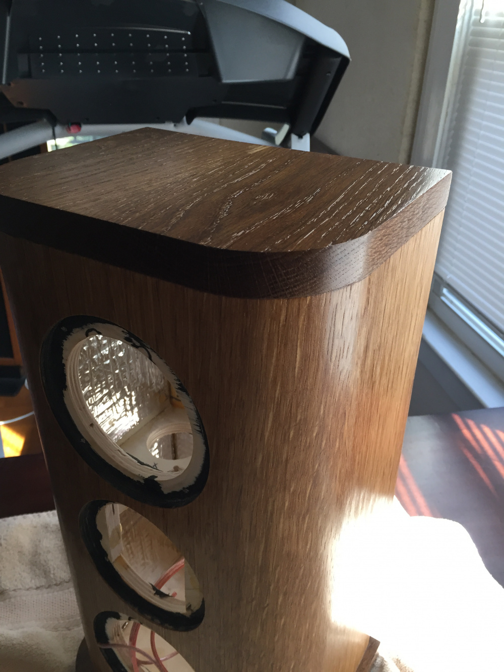
Flush mounted my BZ CQ76B's on my 9" x 7.5" tweeter baffles yesterday. Got an almost perfect fit, using "old school" template and alignment gauges. The baffles will get 3/4" roundovers before mounting them to the main cabinets.
Fits like a glove:
Finally got around to measuring my pair of CQ76B's. Flush mounted them on my DIY IEC test baffle (52.5 x 64" with standard driver offset) and then spun the baffle 0-90 degrees in 7.5 degree steps. VituixCAD interpolates these to 10 degree steps in the graphs below. Used my calibrated Soundworks SoundID mic, placed 1 meter on axis to the tweeter and 58" above the floor. My measurements appear very similar to the ones posted by BoZhen. Tomorrow, I'll re-mount the tweeter to my project baffle, re-measure, and then post the same set of measurements for comparison. Be interesting to see how my baffle placement "decisions" affect the overall response. My baffle is 9" x 39" with 0.75" radius roundovers. The tweeter is located 4.5" down on center from the top.
Will you be taking any distortion measurements? I know I'm not getting around to measuring mine until summer.
Once I have a completed passive crossover in place, yes. Then I can crank the voume up and do an OmniMic distortion test at moderate to loud listening levels. Right now, with no xover in place, I do not want to risk damaging the tweeter. I made the above measurements at a power level somewhat less than 1W/1M. And I did not use a series protection cap. For some unknown reason, I was getting reduced SE (EasyLab) SPL measurements below 500Hz when I switched my Arta jig's 50uF bypass cap into the circuit. So I made all measurements in the "Full" bandwidth position.
$298.00!!!
Did you guys win the lottery?
Can ARTA or others limit bandwidth for distortion sweeps?
Crossover in place doesn't really show the driver's capabilities. Just how you chose to use it.
Have you been busy?
I think I posted that comment several months ago.
No, no lottery for me, but in general, I buy better (more expensive) drivers as I develop my craft.
The Rivals I bought were part of that movement for me. (and they will be missed!)
The Bozhens also - 10 years ago, I would not have bought a $150 tweeter.
Now it's reasonable, if it gives great results.
My understanding is that the Arta jig that I built from dcibel's plans can compensate for the 50uF cap because it places the reference probe after the cap (see Ron and dcibel's comments above). I have a toggle switch on the front of my jig that can switch the cap in and out of circuit during measurements. But I could not get it to work properly. This may have been due to noise and/or the low SPL measurement level that I was using to protect the tweeter. I do not know. Each time I switched the cap into circuit and ran MLS, the FR tail below 500Hz dropped to a lower level.
If you are talking about a distortion measurement in SoundEasy, that's a "single channel" operation. It should be, to ensure relative levels in amplitude are correct, avoiding misleading / bad measurement. I don't recall in SE, but ARTA and REW are fully capable of normalizing the distortion so harmonics are shown relative to the fundamental. In ARTA, just select to view distortion as percent, in REW you can select either percent or dBr units.
For dual channel FR measurement with cap in the feedback loop, you should only really see raised noise floor at low frequency, because both reference and measurement channel will be high passed, then normalized, lifting noise floor at ~6db/oct.
Here are the same set of measurements, using the same tweeter, but this time mounted on my 9" X 39" baffle with 0.75" radius roundovers. Tweeter was mounted on center, 4.5" down from the top of the baffle. The baffle was glued to the main enclosure, which contains two 7" esoteric woofers mounted below the tweeter. This enclosure was placed on top of my DIY turntable, which raises the baffle another 17" above the floor. Mic tip was was 1 meter on axis with the tweeter and 53" above the floor.
As you can see, this baffle shape creates a huge step response bulge from 1 to 1.5kHz, together with an "after shock" on-axis baffle step "suck out" from 2 to 3kHz. The response above 4kHz, however, is roughly the same as the IEC test baffle. Correcting the 2-3kHz on-axis suck out will not be easy. Pounding it flat on-axis will only transfer the problem to the off-axis curves and create a power response blooming effect. An intentional on-axis BBC dip may be the only solution here.
EEsh, that's bad!
Yep you'll have to accept the on-axis dip at 3KHz.
This is the true reason for the "BBC dip" IMHO
Here's another example:
This is a Scan-Speak D2604/833000 dome on an 8" wide cabinet, taken with a Klippel NFS, on a 15.75 x 8" wide cabinet:
In the final speaker I had to accept the dip in the on axis, if I wanted a smooth power or in-room response:
And there's nothing wrong with "accepting" that dip.
Thanks for the feedback. I agree. I recall reading a technical paper a while back concluding that the basic reason for the BBC dip was because of a power response knee (or SPL blooming effect), somewhere in the 1 to 3.5kHz area. This knee was created by many of the common baffle shapes being used.
Actually, it's not that bad at all. The raw response on my baffle is plus or minus 2.5dB from 700 to 20,000Hz. Remember, I have VituixCAD's aspect ratio set to 25dB/dec, which tends to make FR graphs look extra squiggly!")
I'm looking forward to seeing what you end up with. I was thinking... You can probably pull down the 10khz and above rise pretty easily in your xo... And depending on your xo point I assume most/all of the hump around 1.5khz and below will be gone too. That leaves a pretty smooth response from 1khz to 20khz with very low distortion assuming the measurements that are on the web are accurate.
Definitely, I've heard many a design that could have used one. Both diy and commercial.
That will be my basic plan of attack. A high Q filter to bring down the narrow 7kHz bump just a tad. And a separate lower Q filter to bring down the broader 10.5-20kHz bump just a tad. Will leave the 2 to 3kHz dip alone and then juggle the main xover filter parts in an attempt to flatten and pound down the big 1 to 1.4kHz mountain just a tad. This will be a 2.5 way with two 7" woofers sharing the same box volume and alignment, but using separate xover parts. Rolling the lower woofer off at a lower frequency will also be part of my plan to flatten out the big mountain. I hope to have them done and ready to play music next month at Ft Wayne. No finish expected, just raw particle board and good sound.
Another plan of attack would be to boost my baffle roundovers from the current 0.75" radius up to about 1.5". Per modeling programs, this would drop the 1-1.4kHz mountain by about 1dB and boost the 2-3kHz dip by about 1dB. The raw on-axis response would then be plus or minus 1.5dB from 700 to 7000Hz, not plus or minus 2.5dB. So maybe I should get my belt sander out and boost those roundovers. (My largest router bit is only 0.75" radius).
Bill just buy a 1-1/2" radius, they're not that expensive and handy to have. Sooooo much faster and easier.
Just make sure the corner is thick enough.
InDIYana Event Website
I used kerfing to bend 3/4" BB ply for a project. I'm sure that it helped diffraction, and looks really cool.