Site Links
Howdy, Stranger!
It looks like you're new here. If you want to get involved, click one of these buttons!
Quick Links
Categories
Who's Online (0)
Bozhen Esoteric Project

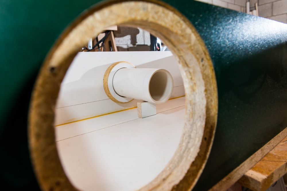
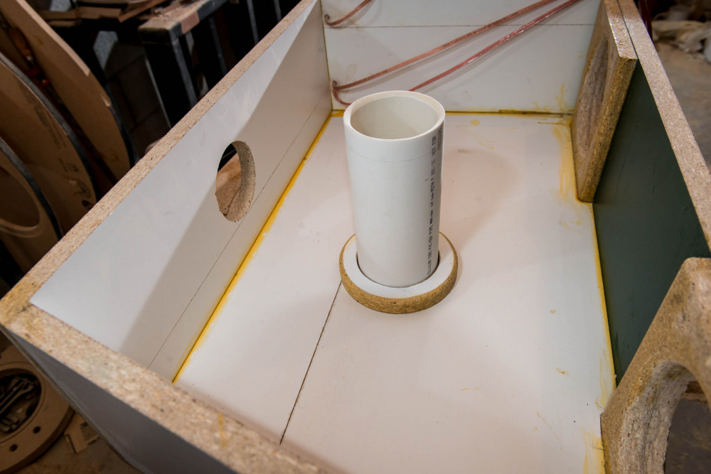
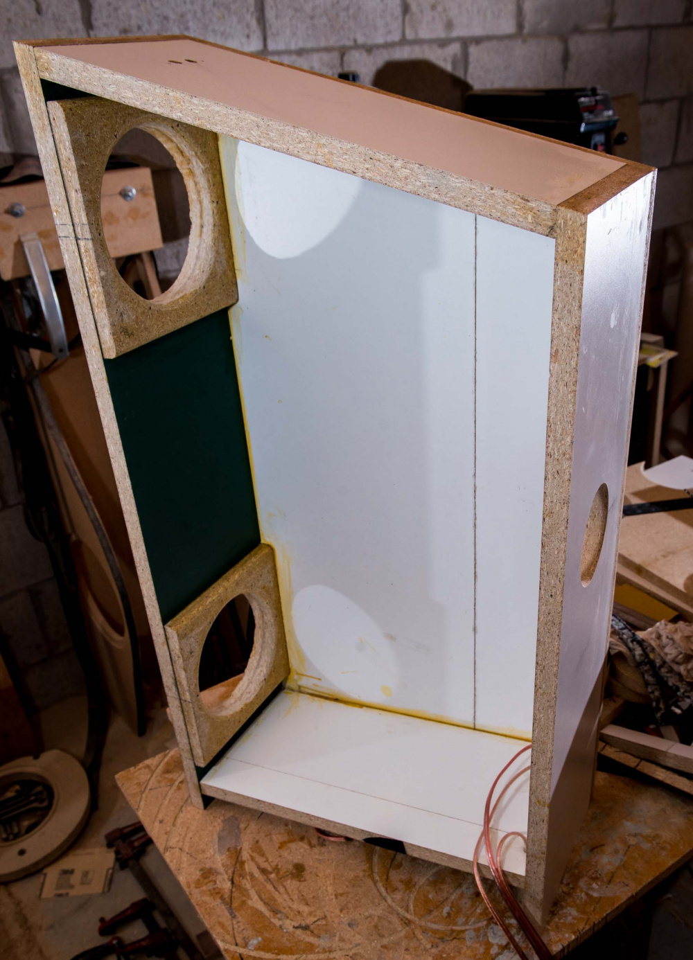
I've been working on these for a while. I demo'd them last year in Iowa, so some of you may have heard them. They were a 2.5 way tower using the Peerless 32mm corundum dome tweeter and dual Dayton 7" Esoteric woofers. Here are a few construction and finished pics of the original speaker before modifications:
To be continued . . .

Comments
Internal stuffing. I rearranged the stuffing several times for the best looking NF port measurement:
Pictures of the speaker at IowaDIY 2022:
I did a little project with those woofers awhile back - I was more than happy with their depth
Here are a couple pics of the adjustable internal braces. I used two of these braces per cabinet. One picture shows the brace before expansion and the other after expansion. Turning the lock nut tightens the brace against the side wall. I "tuned" the side wall resonance at two points, just like you would tune the strings of a musical instrument.
U are definitely nuts - luv it
How do you like the tweeter?
When they came out I dismissed them purely due to the big faceplate. I wonder if it’s removable and able to made smaller with normal tools.
The DA25TX is still available NOS in my neck of the woods… though there are probably equivalent tweeters that I don’t need to modify.
Flat tweeter faceplates- a legacy of C20, IMHO- easy to mount for CNC, and thats about it as far as advantages go.
I located the input jacks at the bottom by cutting a slot wide enough for a pair of banana jacks.
I had bad luck with the DA32. I heard this tweeter in other designs and it sounded very good. But I had messed up something in my xover that made them sound "phasy". It may have also had something to due with the above baffle shape. It measures very well on my large IEC baffle, but it looked horrible on the above small baffle. I also have two pair of the DA25TX and I really like them.
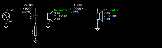
Here is the original crossover. It is mounted in the small cavity at the bottom of the box, just in front of the input jack plate:
Finally, here is the VituixCAD 6 pack for this "failed" design. The response is very choppy looking.
I regret not picking up a pair of DA32TX while they were available.
I didn't like the sound, so I removed the tweeter baffle and replaced it with a new one for the Bozhen CQ76B. I also cut a new hole in the cabinet and moved the lower woofer up much higher.
Closeup pics of the new tweeter baffle, front and back:
Full length views of the revised cabinets:
Revised crossover. Only 2 parts were reused:
So, after installing the CQ76B and belt sanding the roundovers, I re-measured and tweaked. It's still a 2.5 way, but the turnover frequencies have now been raised to about 1800Hz on the upper woofer and 1300Hz on the lower one. Previously, they were about 1kHz on the upper and 500Hz on the lower. I also moved the lower woofer much higher on the cab, and applied 6dB of BSC instead of 4.
The CQ76B tweeter has a rising response beginning at about 4kHz, so I inserted a series 2.7 ohm/0.05mH filter in front it. This leveled things out on axis, but the in-room and power response curves bloomed badly in the 3-5kHz region. It sounded very bright. So I measured/listened/measured and revised the filter to 5.1 ohm/0.125mH.
The sound improved considerably. Still a little on the bright side, but not too bad. The CQ76B has a very detailed and airy high end, which makes it sound a little brighter than most tweeters.
The 3-5kHz in-room and power response blooming still shows up in the model, but flattens out almost completely in my final, actual spin measurement (see graphs). My VituixCAD model is probably somewhat inaccurate because I did not take the necessary 180 degree vertical measurements that are required for non-circular tweeters. Currently, I am unable to do vertical polars using my crappy DIY turntable. I need to build and attach a horizontal outrigger type platform to my turntable. Then, I can turn tower speaker on their side for necessary 180 degree verticals. Right now, I can only turn small bookshelf type speakers sideways for vertical measurements.
Here is the VituixCAD 6 pack model:
And here is the VituixCAD 6 pack of the real crossover, measured 1 meter on tweeter axis and rotated 180 degrees:
This filter looks rather odd to me, very unconventional for a "2.5 way". Generally, lower woofer would roll off around the baffle step to fill in the 6dB of baffle step, and the upper woofer would play through the midrange. These woofers are very nearly running in parallel to the point that it might as well be a 2-way filter. I would think that overall power response could be improved by use of a more conventional 2.5way filter, and possibly an increase in crossover frequency.
Think of something like this for 2.5way filter.
What is listening distance for these graphs?
Keep in mind that spin at 1m is generally not very representative of spin at 2m+ listening distance except for small speakers.
For final design spin at 2m+ listening distance, measure each driver individually on-axis at 1m with filter in place. Enter each driver individually in the crossover with y axis offsets just as original design, but draw straight line from source to driver instead of including crossover. With listening distance in VCAD at 2m+, you will now create a real spin of final speaker which should match design at listening distance very closely. Alternatively, take the whole rig outside and hike it up in the air so you can get good measurement at 2m distance and measure the entire speaker as a single measurement set.
Bill - it looks like you have 1M entered as the X axis location on the upper woofer. Is that correct?
-- wait, that's a small m. Is that 1 millimeter?
Yes, that is 1 millimeter. It should be 0. I must have accidentally bumped this entry up one notch when I was entering the Y axis location. Glad it was not 1 meter; that would have really messed up the model.
The listening distance is 2500mm for all graphs. I'll check into changing it to a more conventional 2.5 way with a higher crossover point. Thanks for the suggestion.
OK, I think I understand what you are saying. VituixCAD cannot recalculate my 1 meter final measurement, made on tweeter axis only, because the program lacks the information needed to triangulate each driver out to the 2.5 meter distance. It needs the Y offsets to do that. I will re-measure each driver on axis with the crossover in place and then re-do my real spin of the final speaker. Will post a new 6 pack tomorrow. Thanks much.
Correct, it won’t give you 2.5m spin data for a 1m single data set. You will find changing listing distance does nothing with the final measurements.
For comparison, you might try looking at your simulated crossover, with listening distance changed to 1m.
Realistically, single measurement of individual speaker drivers on axis with filter in place should give you enough information to validate the crossover, all other measurements for spin data become redundant since you already have measurement data of raw driver, with the filter transfer function confirmed you can be confident in the simulated spin data accuracy.
Nope. These are the only braces. If you look closely at the pictures, you will notice a 1/8" x 1.5" x 1.5" Sorbothane pad on the two ends of the expandable brace. The idea was to "tune" the panel by slowly increasing the pressure as I tapped on the side of the cabinet. As the pressure increases, the frequency of the knuckle rap increases and then turns into a dull sounding thud. I used the 70 duro Sorbothane, which has the approximate softness of a pencil eraser.
I also used a much larger 1/8" thick 70 duro Sorbothane gasket between the tweeter baffle and the main woofer cabinet. You can see it in the pictures above. A knuckle rap on the tweeter baffle produces a dull thud. If you are coming to InDIYana, feel free to give them the knuckle rap test. I'll be bringing these as my non-theme demo pair.
Sorry.
This is critical for VituixCAD2 to function as intended.
A 50 dB scale looks nice for manufacturers or marketting, but when designing a crossover even a 1dB can make or break for design. Consider zooming in to view your CTA2034A over 10dB. It’s disconcerting at first, probably because there are about 5 lines for you to manage, and it’s wobbling all over the place. But after you tune roughly, then tune finely. In the days of lspCAD when I did passive crossovers it can takes months fine tuning, and even end in a complete failure. Now with VituixCAD2, it can take just weeks.
Avoid waves in the power response and PIR response. Smooth is best. It will be hard to be perfectly flat (unless you have a purely omnidirectional speaker) so a gentle downward slope is what it will be.
No no, 4th try has the measurement process down for design. It’s just the last screenshot above for validation, is a measurement of complete speaker at 1m. There’s a reason this 1m “spin” doesn’t match the simulation at 2m+ very well.
For comparison of simulation with measurement of completed speaker, there are a few options.
1. Easiest is to change listening distance in simulation to measurement distance for direct comparison.
2. Increase measurement distance to simulated listening distance, often not practical indoors.
3. Measure drivers individually with filter in place. With 2 channel measurement jig you can verify both acoustic response and electrical transfer function for verification. I mentioned above, completing full set of spinorama data is a bit redundant once you've compared simple on-axis for validation. You can measure each driver individually on-axis with filter, compare to simulated response of driver on-axis with filter. You can also place measurement jig in between crossover and speaker, measure the loopback reference channel to capture the filter transfer function. Compare on-axis measurement of complete system on design axis with simulation (listening distance = measurement distance) provides validation of overall response to make sure all delay and amplitude information is correct.
If I followed correctly...He did measure each driver on axis for xo design. To VALIDATE, he then measured the speaker with xo in place on tweeter axis. But this should be done at 2.5+m so dcibel was pointing out a way to approximate that in VituixCAD by measuring each driver on axis with xo in place IF he can't get a 2.5+m measurement without reflections..
Correct. For the far field modeling measurements, the tweeter and woofer drivers were each measured 1 meter on axis for the xo design spins. The first 180 degree spin was made on axis with the tweeter. Then I lowered the mic to the height of the upper woofer axis and did another 180 degree spin on the upper woofer only. The lower woofer holes were plugged off during this spin. I did not measure the lower woofer, but simply used a copy of the upper woofer measurement set for the lower woofer in the model.
For the validation test with crossover in place, I kept the mic on tweeter axis and did just one 180 degree spin. I was following the instructions from an old ASR thread which probably needs to be updated:
https://www.audiosciencereview.com/forum/index.php?threads/how-to-make-quasi-anechoic-speaker-measurements-spinoramas-with-rew-and-vituixcad.21860/
It's a bit of a crap instruction TBH. Lots of words and convoluted process. 1m distance is at least suggested for "most bookshelf speakers", however reasons quoted is baffle width, not speaker distance/angle relative to mic. CTA-2034 standard spinorama must be presented at 2m distance, which is what VituixCAD will provide with individual driver data and listening distance at set to 2m. 1m spin can be very different especially for larger speakers, but full CTA-2034 spinorama isn't really needed for validation, but can be done at 1m with individual driver measurements. However, probably less likely ASR guys want to start dissecting speakers to measure drivers individually. In any case, validation measurement should show near perfect alignment with simulation.
But...instructions can be worse. There is this disaster recently posted at MiniDSP site:
https://www.minidsp.com/applications/rew/isobaric-polar-plots