@jhollander said:
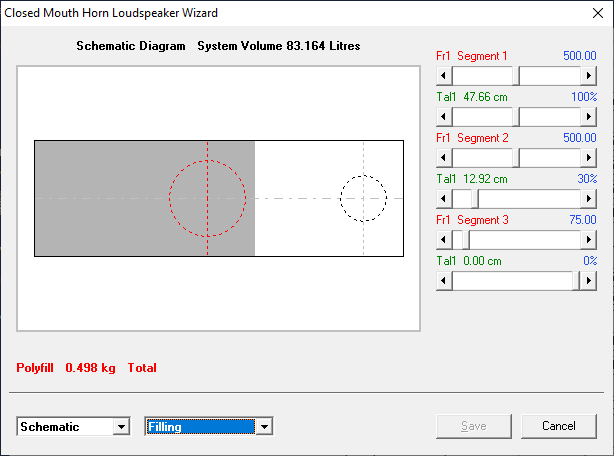
In the wizard screens you will also find the Kg of polyfill that gives you a decent starting point. I like to provide removable panel to adjust the stuffing. My preference has been to put the stuffing between the driver and the port. You need to be careful the insulation doesn't poop out the port.
Thanks John, a removable panel is a great idea. I also had an idea to avoid speaker poop. I can glue a bit of screen door material on top of a windowpane brace to contain the area to be stuffed.
Honestly I'd prefer to avoid the whole loose stuffing game and use the bonded dacron sheets from Meniscus (or Joann fabric in a pinch). My problem there is not knowing the correct acoustic resistance of those materials in mks rayl units for HornResp!
Looks like the last model I posted needs about 0.5 kg of Poly-fil spread throughout that area.
@rjj45 said:
Honestly Keith - I think that's probably an optimum TL for that woofer. I kept playing with the basic offset port model for the Ciare, and was coming to the conclusion that it wanted a big box to shine.
You done good!
I don't know offhand about Ql - I know Jeff gave some advice that I saved somewhere.
Thanks! I appreciate your help reviewing my hornresp model and sharing your knowledge!
I've used that bonded dacron from Meniscus in a MLTL. It worked very well and was easy to use. It's 0.75 Lbs/Ft^3 if you stack the pieces in there and don't compress them. Just figure out your stuffed volume in cubic feet, mulitply that by 0.75 to get the weight in pounds, then multiply that by 0.4536 to get the weight in Kilograms.
@PWRRYD said:
I've used that bonded dacron from Meniscus in a MLTL. It worked very well and was easy to use. It's 0.75 Lbs/Ft^3 if you stack the pieces in there and don't compress them. Just figure out your stuffed volume in cubic feet, mulitply that by 0.75 to get the weight in pounds, then multiply that by 0.4536 to get the weight in Kilograms.
Thanks for the experience there Craig! I think I still have nerdy simulation problem though. I don't know what to use as the acoustic impedance in mks rayl units for the bonded dacron in HornResp. Paul K knows how to model that stuffing in the Martin King MathCad models, but those don't use acoustic impedance / rayl units to describe the behavior. Seems there isn't a transfer function to back that kind of information out.
I don't know what to use as the acoustic impedance in mks rayl units for the bonded dacron in HornResp. Paul K knows how to model that stuffing in the Martin King MathCad models, but those don't use acoustic impedance / rayl units to describe the behavior. Seems there isn't a transfer function to back that kind of information out.
Would it be possible to build an experimental TL to figure this out? Build a box with the baffle and side held together temporarily with clamps and gaskets. Add stuffing, clamp it up, then take a NF port measurement. When the NF port peaks match the model, you would know the acoustic impedance.
Bill - I think you're right. I should be able to figure this out with a test box and some time. I spend so much effort trying to research when I could just go the empirical route - then share with the world and do my part to contribute to DIY. Only things standing in my way now are my own schedule / free time. We'll see if I get around to an experiment or not.
I'll commit to conducting a future experiment as well. Then we can compare our findings. I'll build it with a movable baffle board so the woofer position can easily be adjusted from the end of the line up to as much as 24" down the line. And I will use movable internal partitions so the total line length and port positions can be adjusted substantially, as well as stuffing density and position. Should be fun.
That's how I've done it. I have been using polyester batting sewn into a tube or envelop then stuffing it with polyfill or fiberglass. Stuff it into the box then adjust the stuffing and look at the port resonances
That’s what I have been thinking, but it’s several months out at present. PMC makes a big deal about using proprietary lining - so I started to think about test MLTL box with a removable side. Test with Wally World poly fill and then with Dow 703 on the walls. Measure exit resonances and woofer T/S for each.
But Chahly - Stahkist don't want speakers that look good, Stahkist wants speakers that sound good!
Possibly a mixture ie soft / firmer / softer along the line / or different treatments for around bends of the line?
Should be an interesting project/ test !
For my ported boxes and TLs, I like to use a variable density insulation method with Polyfill, Roxul, and Fiberglass in the same style batting envelope. I almost never use foam due to the adsorption coefficients. Same with lining the walls. The concept is a airflow resistance plus frequency adsorption.
@tajanes said:
Possibly a mixture ie soft / firmer / softer along the line / or different treatments for around bends of the line?
Should be an interesting project/ test !
I'll put one bend in my experimental line to test this as well. Most lines have at least one bend.
@jhollander said:
For my ported boxes and TLs, I like to use a variable density insulation method with Polyfill, Roxul, and Fiberglass in the same style batting envelope. I almost never use foam due to the adsorption coefficients. Same with lining the walls. The concept is a airflow resistance plus frequency adsorption.
Hi John, checking to see if I followed you here... You call it a batting envelope. Do you mean from outside to inside it's Roxul / rockwool, then fiberglass, then polyfill? Kinda like an acoustically resistant jelly donut ? I suppose doing that would require trial and error to match a model same as anything else.
I picked up the variable density concept up from some old JB posts referencing someone else. The layers were outside to inside soft to firm or increasing density. Dan N had done something similar on a mid range TL. My adaptation was to try to figure out how to do this that was repeatable and consistent. So I started to making fabric pockets with insulation sandwiches that I could weigh and remove and adjust as needed.
Yes you would need to test.
This picture shows a 3 part layer wool, polyfill, and then Roxul.
As you are testing, keep good records as to how each material compares to Hornresp's polyfill recommendation. We should be able to put together a spreadsheet of damping material fudge factors. Unless the data varies too much by driver t/s parameters, length of line, bends, cross sectional area, etc.
Difficult, yes. But can it be done in a repeatable manner? I would probably start by measuring the effects of each damping material type separately. Then move on to the more difficult task of measuring the effects of mixed materials. I would probably tease or fluff up the material somewhat to get the material to evenly fill out the required line segment. Then, after getting the test line to match the model, I could pull the damping material out and measure it on a calibrated scale. Then I would know the exact lbs/ft3 or grams/cm3 of a particular damping material that is required to match the model.
I too typically do the progressively denser damping material in my midrange sub-enclosures. I like to leave lots of free air space right behind the driver. Then some lightly fluffed poly fill, then a 1" thick layer of open cell foam, finally followed by the heavier 1" thick recycled denim stuff. Braces placed in just the right spots hold the maverick poly fill in place.
@4thtry said:
Difficult, yes. But can it be done in a repeatable manner? I would probably start by measuring the effects of each damping material type separately. Then move on to the more difficult task of measuring the effects of mixed materials. I would probably tease or fluff up the material somewhat to get the material to evenly fill out the required line segment. Then, after getting the test line to match the model, I could pull the damping material out and measure it on a calibrated scale. Then I would know the exact lbs/ft3 or grams/cm3 of a particular damping material that is required to match the model.
I can measure the volume of were the stuffing goes, the weight of the stuffing, but it's a crap shoot if I fluffed the polyfill and fiberglass the same. Polyfill is the worse. I can never tease it out the same way. I got close when I started to make Polyfill balls-o-stuffin. Wayyy more effort that its worth imo.
Don & Keith, I've been using the detailed info from your various Hornresp models above as a tutorial to learn Hornresp. After a few days of clicking around, I have now reached the point where I can duplicate Keith's two models exactly. Thanks for posting all the detailed info, this really helps. I have a couple questions about the models:
1) I noticed that you used the advanced driver parameter values for a semi-inductance model in both of your models. The Le is 2.91mH instead of the spec sheet value of 1.75mH. What would be the reason for using this value instead of the mfg's value? I noticed that this makes a significant difference in the model's high frequency roll off rate.
2) The path length is entered as 39.2cm on both models. However, when I double click to make Hornresp automatically calculated the path length, I get a path length of 54.5cm on the first model and 43.1cm on the 2nd model. Not a big deal, as this makes very little difference in the model. Just wondering how you came up with 39.2 cm. Thanks.
I asked Keith why his T/S were diff from mfg, and he said that he tested them after breakin.
The Path parameter is the distance from the woofer (front) output to the output of the port (MLTL) or plenum terminus (TL). If you zero it out, you will probably see some ripples in the FR 200-400Hz. Although HR can calculate path length, it doesn't know whether a port is on the front of back of the box. It's a minor parameter, that's nice to include, but not critical unless you obsess for totally flat FR in the simulation. Oh, wait a sec, of course we all obsess about small details! It's DIY!
Hope this helps!
We are finishing our house move this coming Monday, and I will begin the HR tutorial doc.
But Chahly - Stahkist don't want speakers that look good, Stahkist wants speakers that sound good!
Bill - I don't actually know how HornResp is calculating acoustic path length on the MLTL setup. I did a search in the help file and all I found was a comment about the path length being the shortest distance between the driver and the port as if they were point sources. I didn't think enough to worry about it before your question. Sounds like I still don't really need to be concerned, but I maintain an academic interest.
As for the semi-inductance model, I used it because Brian Steele suggests it on his DIY subwoofer page. Seemed like a more accurate way of modeling to me... and accurate is always better in my book.
Thanks for the info. Looks like the semi-inductance method is extremely important, especially when designing a 3 way with an xover in the 300Hz to 1kHz region.
@jhollander said:
In the wizard screens you will also find the Kg of polyfill that gives you a decent starting point. I like to provide removable panel to adjust the stuffing. My preference has been to put the stuffing between the driver and the port. You need to be careful the insulation doesn't poop out the port.
OK John... I'm trying to convince myself to follow your advice on the removable panel. I'm overthinking (as I do) and I'm worried I won't really get the benefits with the way I designed it. Not sure I can get my arm in there and distribute stuffing equally.
I did two panels, actually... one at the bottom for easy crossover installation complete with 3/4" birch ply strips to screw into. The stuffing panel I could not make wide enough for my arm to get in there if I did the birch ply backing strips again, so I just designed a half thickness rabbet joint instead. I'm worried that won't be strong enough with a 3/8" flange being screwed into.
My alternative is to just use Meniscus dacron and roll the dice that my HornResp model matches well with the 0.75 lb/ft^3 density of that material.
Exactly how FAR do you think I'm overthinking this?
@4thtry said:
Why not make the entire back panel removable? Then you would have easy access to everything.
Well... I suppose that is possible on a test cabinet. Honestly I worry about having a giant leak path to contend with on a full floorstanding tower. I also feel like that defeats a large part of the bracing scheme as I try to connect the front and rear. I'd probably need 30-40+ screws too around the perimeter and across the braces to reconnect them.
Am I overcomplicating things again?
Yes... Yes I am. Sort of. Will post an update soon with a compromise CAD solution. Thanks for making me think again Bill!
Comments
Thanks John, a removable panel is a great idea. I also had an idea to avoid speaker poop. I can glue a bit of screen door material on top of a windowpane brace to contain the area to be stuffed.
Honestly I'd prefer to avoid the whole loose stuffing game and use the bonded dacron sheets from Meniscus (or Joann fabric in a pinch). My problem there is not knowing the correct acoustic resistance of those materials in mks rayl units for HornResp!
Looks like the last model I posted needs about 0.5 kg of Poly-fil spread throughout that area.
Thanks! I appreciate your help reviewing my hornresp model and sharing your knowledge!
I've used that bonded dacron from Meniscus in a MLTL. It worked very well and was easy to use. It's 0.75 Lbs/Ft^3 if you stack the pieces in there and don't compress them. Just figure out your stuffed volume in cubic feet, mulitply that by 0.75 to get the weight in pounds, then multiply that by 0.4536 to get the weight in Kilograms.
Thanks for the experience there Craig! I think I still have nerdy simulation problem though. I don't know what to use as the acoustic impedance in mks rayl units for the bonded dacron in HornResp. Paul K knows how to model that stuffing in the Martin King MathCad models, but those don't use acoustic impedance / rayl units to describe the behavior. Seems there isn't a transfer function to back that kind of information out.
Would it be possible to build an experimental TL to figure this out? Build a box with the baffle and side held together temporarily with clamps and gaskets. Add stuffing, clamp it up, then take a NF port measurement. When the NF port peaks match the model, you would know the acoustic impedance.
Bill - I think you're right. I should be able to figure this out with a test box and some time. I spend so much effort trying to research when I could just go the empirical route - then share with the world and do my part to contribute to DIY. Only things standing in my way now are my own schedule / free time. We'll see if I get around to an experiment or not.
I'll commit to conducting a future experiment as well. Then we can compare our findings. I'll build it with a movable baffle board so the woofer position can easily be adjusted from the end of the line up to as much as 24" down the line. And I will use movable internal partitions so the total line length and port positions can be adjusted substantially, as well as stuffing density and position. Should be fun.
That's how I've done it. I have been using polyester batting sewn into a tube or envelop then stuffing it with polyfill or fiberglass. Stuff it into the box then adjust the stuffing and look at the port resonances
That’s what I have been thinking, but it’s several months out at present. PMC makes a big deal about using proprietary lining - so I started to think about test MLTL box with a removable side. Test with Wally World poly fill and then with Dow 703 on the walls. Measure exit resonances and woofer T/S for each.
Possibly a mixture ie soft / firmer / softer along the line / or different treatments for around bends of the line?
Should be an interesting project/ test !
For my ported boxes and TLs, I like to use a variable density insulation method with Polyfill, Roxul, and Fiberglass in the same style batting envelope. I almost never use foam due to the adsorption coefficients. Same with lining the walls. The concept is a airflow resistance plus frequency adsorption.
I'll put one bend in my experimental line to test this as well. Most lines have at least one bend.
Hi John, checking to see if I followed you here... You call it a batting envelope. Do you mean from outside to inside it's Roxul / rockwool, then fiberglass, then polyfill? Kinda like an acoustically resistant jelly donut") ? I suppose doing that would require trial and error to match a model same as anything else.
? I suppose doing that would require trial and error to match a model same as anything else.
I picked up the variable density concept up from some old JB posts referencing someone else. The layers were outside to inside soft to firm or increasing density. Dan N had done something similar on a mid range TL. My adaptation was to try to figure out how to do this that was repeatable and consistent. So I started to making fabric pockets with insulation sandwiches that I could weigh and remove and adjust as needed.
Yes you would need to test.
This picture shows a 3 part layer wool, polyfill, and then Roxul.
That’s a beautiful mouse nest.
https://www.jfcomponents.com/
As you are testing, keep good records as to how each material compares to Hornresp's polyfill recommendation. We should be able to put together a spreadsheet of damping material fudge factors. Unless the data varies too much by driver t/s parameters, length of line, bends, cross sectional area, etc.
It's very difficult to keep a consistent insulation density with lose fill like polyfill or torn up or pulled apart batts.
Difficult, yes. But can it be done in a repeatable manner? I would probably start by measuring the effects of each damping material type separately. Then move on to the more difficult task of measuring the effects of mixed materials. I would probably tease or fluff up the material somewhat to get the material to evenly fill out the required line segment. Then, after getting the test line to match the model, I could pull the damping material out and measure it on a calibrated scale. Then I would know the exact lbs/ft3 or grams/cm3 of a particular damping material that is required to match the model.
I too typically do the progressively denser damping material in my midrange sub-enclosures. I like to leave lots of free air space right behind the driver. Then some lightly fluffed poly fill, then a 1" thick layer of open cell foam, finally followed by the heavier 1" thick recycled denim stuff. Braces placed in just the right spots hold the maverick poly fill in place.
I can measure the volume of were the stuffing goes, the weight of the stuffing, but it's a crap shoot if I fluffed the polyfill and fiberglass the same. Polyfill is the worse. I can never tease it out the same way. I got close when I started to make Polyfill balls-o-stuffin. Wayyy more effort that its worth imo.
Don & Keith, I've been using the detailed info from your various Hornresp models above as a tutorial to learn Hornresp. After a few days of clicking around, I have now reached the point where I can duplicate Keith's two models exactly. Thanks for posting all the detailed info, this really helps. I have a couple questions about the models:
1) I noticed that you used the advanced driver parameter values for a semi-inductance model in both of your models. The Le is 2.91mH instead of the spec sheet value of 1.75mH. What would be the reason for using this value instead of the mfg's value? I noticed that this makes a significant difference in the model's high frequency roll off rate.
2) The path length is entered as 39.2cm on both models. However, when I double click to make Hornresp automatically calculated the path length, I get a path length of 54.5cm on the first model and 43.1cm on the 2nd model. Not a big deal, as this makes very little difference in the model. Just wondering how you came up with 39.2 cm. Thanks.
I asked Keith why his T/S were diff from mfg, and he said that he tested them after breakin.
The Path parameter is the distance from the woofer (front) output to the output of the port (MLTL) or plenum terminus (TL). If you zero it out, you will probably see some ripples in the FR 200-400Hz. Although HR can calculate path length, it doesn't know whether a port is on the front of back of the box. It's a minor parameter, that's nice to include, but not critical unless you obsess for totally flat FR in the simulation. Oh, wait a sec, of course we all obsess about small details! It's DIY!
Hope this helps!
We are finishing our house move this coming Monday, and I will begin the HR tutorial doc.
Bill - I don't actually know how HornResp is calculating acoustic path length on the MLTL setup. I did a search in the help file and all I found was a comment about the path length being the shortest distance between the driver and the port as if they were point sources. I didn't think enough to worry about it before your question. Sounds like I still don't really need to be concerned, but I maintain an academic interest.
As for the semi-inductance model, I used it because Brian Steele suggests it on his DIY subwoofer page. Seemed like a more accurate way of modeling to me... and accurate is always better in my book.
https://www.diysubwoofers.org/misc/semi-inductance.html
Thanks for the info. Looks like the semi-inductance method is extremely important, especially when designing a 3 way with an xover in the 300Hz to 1kHz region.
semi-inductance is a good thing to include for any cabinet model, accurate driver impedance only improves the accuracy of the model. I posted some basic instruction on how to extract these parameters for any driver from tracing the impedance here:
https://www.htguide.com/forum/articles/do-it-yourself-diy/927414-vituixcad-extended-impedance-model-for-any-driver
@jhollander
OK John... I'm trying to convince myself to follow your advice on the removable panel. I'm overthinking (as I do) and I'm worried I won't really get the benefits with the way I designed it. Not sure I can get my arm in there and distribute stuffing equally.
I did two panels, actually... one at the bottom for easy crossover installation complete with 3/4" birch ply strips to screw into. The stuffing panel I could not make wide enough for my arm to get in there if I did the birch ply backing strips again, so I just designed a half thickness rabbet joint instead. I'm worried that won't be strong enough with a 3/8" flange being screwed into.
My alternative is to just use Meniscus dacron and roll the dice that my HornResp model matches well with the 0.75 lb/ft^3 density of that material.
Exactly how FAR do you think I'm overthinking this?
Thanks!
Why not make the entire back panel removable? Then you would have easy access to everything.
Well... I suppose that is possible on a test cabinet. Honestly I worry about having a giant leak path to contend with on a full floorstanding tower. I also feel like that defeats a large part of the bracing scheme as I try to connect the front and rear. I'd probably need 30-40+ screws too around the perimeter and across the braces to reconnect them.
Am I overcomplicating things again?
Yes... Yes I am. Sort of. Will post an update soon with a compromise CAD solution. Thanks for making me think again Bill!