Site Links
Howdy, Stranger!
It looks like you're new here. If you want to get involved, click one of these buttons!
Quick Links
Categories
In this Discussion
Who's Online (0)
Peerless based 8" 3-way build

in DIY
Shooting for a compact sealed 3-way. Very much inspired by JR's GRS 8" 3-ways.
T: XT25SC90-04
M: TC9FD18-08
W: 830667
Enclosure dimensions:
10"W, 18"H, 11"D
Modeled with .5ohm tagging along for inductor DCR.
This alignment keeps excursion in check until down in the single digits with up to 75watt... Which would yield Just under 105db at 1m above ~60hz, if the little mid can keep up.


Comments
Thats a tight package, and + going sealed
I've done an 3 way with the 830667. My cabinet was 0.7cu ft, IIRC. It's doable. The baffle diffraction loss means that bump around 80-90 Hz is less in full space than the 2pi simulation
The only downside the low sensitivity, I think it was about 83dB/2.83V after BSC. Consider using them in pairs.
Yeah this is definitely going against my normal urge for higher sensitivity. I've already cut and started gluing so pretty set on one per side by this point.
Good to hear what is in my head works in practice at least.
Anyone have much experience with surface mounting mids? Because cutting a rebate for the TC9 shape is pretty far down my list of "fun things to do". Wondering what kind of diffraction impact I should expect from the nearby tweeter (3.5" center to center). I briefly thought about turning it 45deg in case that would have less impact, but that would look pretty goofy to me.
I have freehanded rebates with the router before, such as this one for the Dayton planar (below). But afterwards I was drenched in sweat from the concentration as I knew the entire time I was a split second away from screwing it up. The particle board I'm using now would be more difficult to do because it is not as easy to see the markings on. I can pretty much guarantee failure on that.
Love you choice of drivers!
I used the TC9's in a little pair of computer speakers for my wife. I wimped out and just rear mounted them. I toyed with the idea of making a router template on the 3D printer, but decided it was too many steps for what was supposed to be a quick, simple project.
you could consider using felt - to bring the baffle out a bit (around both the mid and tweeter)
I brought a pair of 3 ways to Indy a couple years ago that used the TC9FD as the mid. I used some 1/2" felt to midigate the surface mounting and the effects of the grills. They measured great and sounded good to me.
I read somewhere on the DIY Audio Forum that the TC9FD are excellent drivers and have been used in place of the $can$peak driver of the same size in a FAST build with the RS225.
Geoff
I don't mind the TC9 as it sounds good, but I have not heard the 10F by comparison and felt it was just fantastic either. I think I'd take the TC9 and save the money since I don't find the 10F to really be that superior.
InDIYana Event Website
Still very new to 3-ways. I've designed one, but that was quite the knock down drag out affair with a CD mid.
It seems folks try to stay outside the 300-800hz range for audible reasons. The rising distortion on the 830667 makes it seem plausible to cross up to around 700hz. Don't know if it would be prudent to try crossing the TC9 down around 300hz...
For mid chamber I'm planning to use some 32oz plastic festival mugs. That comes in just under 1liter. But by this point I'm basically guessing that will work since I have no experience with designing midrange enclosures.
At max rated RMS wattage (30watt) TC9 is knocking on the door of 100db at 1m.. this is what xmax looks like:

I'm told a series resistor will help tame the Q peak. So I suppose that would reduce excursion in that range and keep it safer to cross near 300hz? Though, that is all before baffle step throws it's wrench into the response.
Honestly I'd like to not cross so low mostly for crossover cost reasons. Well that, and I think JR's build crossed around 1khz (sealed back mid).. I liked how it was able to fill out the midbass region.
I think I usually xover within 300-800 for an average 3way, not outside of it.
InDIYana Event Website
ok, maybe I misread things then. That helps.
Seems 3-500 works very well for alot of small cone mids, 4" to 7". Some 3" are bandwidth limited to 500+. Using a 2" mid, dome or cone, lends more to 700-1k range.
InDIYana Event Website
My initial thought was 500-600hz as a starting point, purely based on baffle step range, and adjust from there. But then I veered off into the weeds while researching.
What I often see with regards to "problems" in crossover between midrange and woofer stem from lacking measurement resolution through midbass range, possibly problems with near/far merge, and definitely problems with designing using only measurements from tweeter axis at 1m for all drivers. Result is "bad data" that when tuned for a pretty flat graph, create unbalanced sound.
As far as overall FR goes, if I had a rule of thumb, it would be to aim for a crossover around here:
This point ensures that midrange is not stressed to play into full space ("below baffle step"), allowing for full use of the drivers sensitivity, and most woofers will have no problem with a crossover in this range either. The FR bump from cabinet diffraction gets rolled into the crossover rolloff. That guideline is for FR balance only, so distortion, max output limits by excursion and power handling have to be considered as well, so most dome mids won't be able to achieve this low of a crossover. TC9 I think will be just fine.
Hi,
I've used the TG9 in a very similar application to the one you are describing.
You may or may not find it useful, but I had a thread on PE a while ago describing my effort. I tested the TG9 and found the lower crossover point both xmax and HD limited- but it has excellent HD down low (see post 20):
https://techtalk.parts-express.com/forum/tech-talk-forum/1444113-budget-duelund-three-way
I'm sure you're aware the TC9 and TG9 are very similar. Timothy Feleppa tested both on his site:
https://feleppa.com.au/speakermeasmid.html
Recessing the frame of the TG9 is one of the most unpleasant experiences I can describe in my speaker building efforts to date. I have tried most of the various methods described on the interwebs and wish I just had a CNC.
Your project concept sounds excellent BTW!
Cheers,
Greg
Wow thanks guys! Juicy info!
I've got top/bottom and sides glued up with a brace between the sides as sort of a carcass ready to glue the fronts and backs onto.
Planning on offsetting the m/t. For fun I plonked the baffle width into the "golden ratio". Seemed reasonable so running with that offset: 1, 3/16" off center.
I want to cut a rabbit as a glue channel to press the lip of the mug into. Hopefully creating a bit of a mechanical seal around the lip bead with the construction adhesive in case it doesn't provide the best adhesion to the plastic. Only problem with that is now I'm defining exact driver locations before the baffle is glued on. Up to this point I never do that. Because even if you get it perfect and clamped down; a not well aligned clamp can slowly pull the piece out of location while you are not looking. If you don't catch that before the glue sets up you are hosed. So a precision glueup is a pain, but I'll have to try this time. I marked the inside and outside of the panels as a guide. Though pencil doesn't show up the greatest on this particle board.
For the surface vs flush mount of the TC9. I keep flip flopping.. But currently I'm thinking just surface mount it and deal with any consequences. The xt25 has a more rapidly falling response off axis compared to a dome. So at least the HF should be less effected by such baffle irregularities from what I've researched... less energy there to dance on those edges.
I concur with @dcibel
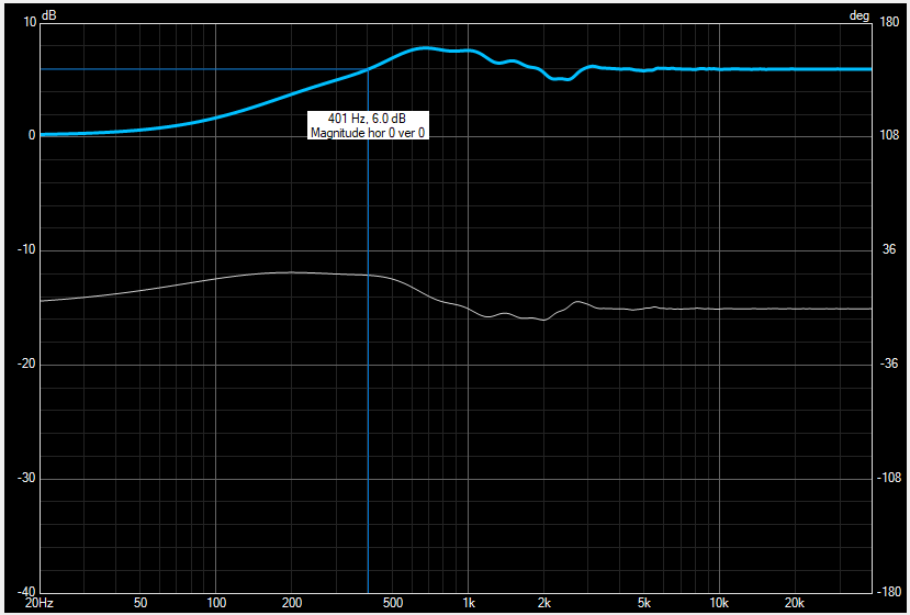
I also have some useful data of the 830667 in a sealed 0.7 cu ft cabinet 8.5" wide that I can share:
All measurements 2.83V @1m.
Note the low sensitivity level, and the subtle bass bump around 80-100Hz, and the F6 is about 40Hz, just like the OP's simulation.
The SLS's single aluminium ring for inductance control means that the odd order distortion starts to rise in the midrange, so based on harmonic distortion alone the XO point is best at ~400Hz or lower.
Your precise crossover point depends on phase matching with the TC9. The TC/TG9 is a full range so it should play down to 150-200Hz without trouble, unlike pure midranges with limited excursion. So you might be able to go with 2nd order acoustic slopes on the high and low pass of the 3 way.
This may improve your power response/predicted in room response. And reduce your crossover parts count/cost.
I'm not sure i agree with the 400Hz as the best xover point. Since the SLS8 seems to be 84dB sensitivity, and the -40dB spot for audibility places curves below 44dB as theoretically okay. Granted -50dB is better, but just not possible here. Once you tilt the response for BSC, the HD will reduce there too. I would look at 600Hz as a better approximation and not think twice.
InDIYana Event Website
"400Hz" is over-simplification of what I was conveying in that image. Narrow baffle will have higher point. Wide baffle maybe a bit lower. Baffle shown is 260mm wide tower speaker.
I was referring to Thanh's comment, not yours, Reid.
InDIYana Event Website
All good then.
Wow, being able to measure the bump in the woofer response. Thats pretty nuts!
I really appreciate all the info guys!
Looks like 450hz is the rough mid point in baffle step for 10" wide baffle. I thought I calculated 550hz before, but I was mistaken (need to lay off the sauce when I'm dorking with this stuff). Whether that really means anything in the context of where to crossover.. IDK. Not centering the midrange on the baffle will probably mess with that. But it was something to start with.
I had heard ~1.2 wavelength crossover point is a reasonable c-c spacing on m/t. 3.5" makes for ~4.6khz
Those numbers cover over 3 octaves. So checks out initially for best practice to maintain safe impedance. Not that it seems to be adhered to all that often anymore. I suppose available tools offer better precision to fly closer to the sun without burning up nowadays.
That is where I was deriving the basic ballpark numbers to shoot for until the drivers tell me where they want to cross. Ideally (for me) I might try a little higher on m/w crossover point to keep component values lower and cheaper. But that is only if the drivers want to play ball. Keeping frugality in mind is always a bullet point in my builds. Though I might throw some extra $ at trying something new at times.
I like the CTC wavelength as the xover freq. The 1.2x spacing is better for vertical off axis. There are drivers that fudging the number still works too. For instance, a planar tweeter spaced to a 5.25" woofer at 6" CTC I have xoverd at 3k without issues. I tend to fudge for smaller wavelengths. 6" is close to 2k, as a ballpark, and I don't tend to go more than 1.5x the CTC freq. IE, 2k would be 3k max.
Just some food for thought.
InDIYana Event Website
Does the narrow vertical response of tall tweeters play into the ability to fudge that much?
For 1:1, 3.5" is around 3.9khz, which incidentally looks like the spot on the factory TC9 graph where the off axis responses really begin to break away from each other. Does crossing at or below the point of narrowing dispersion tend to help horizontal off axis performance? I imagine it usually would. My limited personal experience has been a bit of a mixed bag. Though my efforts sofar to measure off axis is probably so poor as to render any results highly suspect anyway. I need a turn table rig.
So it looks like Liquid nails Fuze-it is compatible with everything except Polyethylene and Polypropylene. I bet these mugs are one or the other. Just trying to determine which, because JB Weld 50133 is rated compatible with polypropylene. Seems alot of consumer grade stuff is polypropylene so that is where I'm leaning. There are 0 markings molded into them. Any folks here familiar with differences in these plastics? Or at least a better guess than mine.
I guess I would just use silicone caulk to attach things.
Polypropylene is notoriously difficult to bond.
Those cups look like Polyethylene to me - what code is in the bottom of them, if any?
https://extension.usu.edu/archive/plastics-for-storage
You could also put a piece of wood across the back and run a long screw to the back of the baffle to clamp it in place.
True.. Silicone doesn't really shrink so it shouldn't pull away or create a gap. And remains nice and pliable to maintain a seal.
If that seems too flimsy, then external bracing can be added.
Yeah Steve there were no molded in markings to look up unfortunately.
Make sure to let the silicone fully cure before putting in the drivers, as the fumes can destroy certain surrounds and adhesives.