Site Links
Howdy, Stranger!
It looks like you're new here. If you want to get involved, click one of these buttons!
Quick Links
Categories
In this Discussion
Who's Online (0)
Anyone interested in taking on a 3D waveguide project?

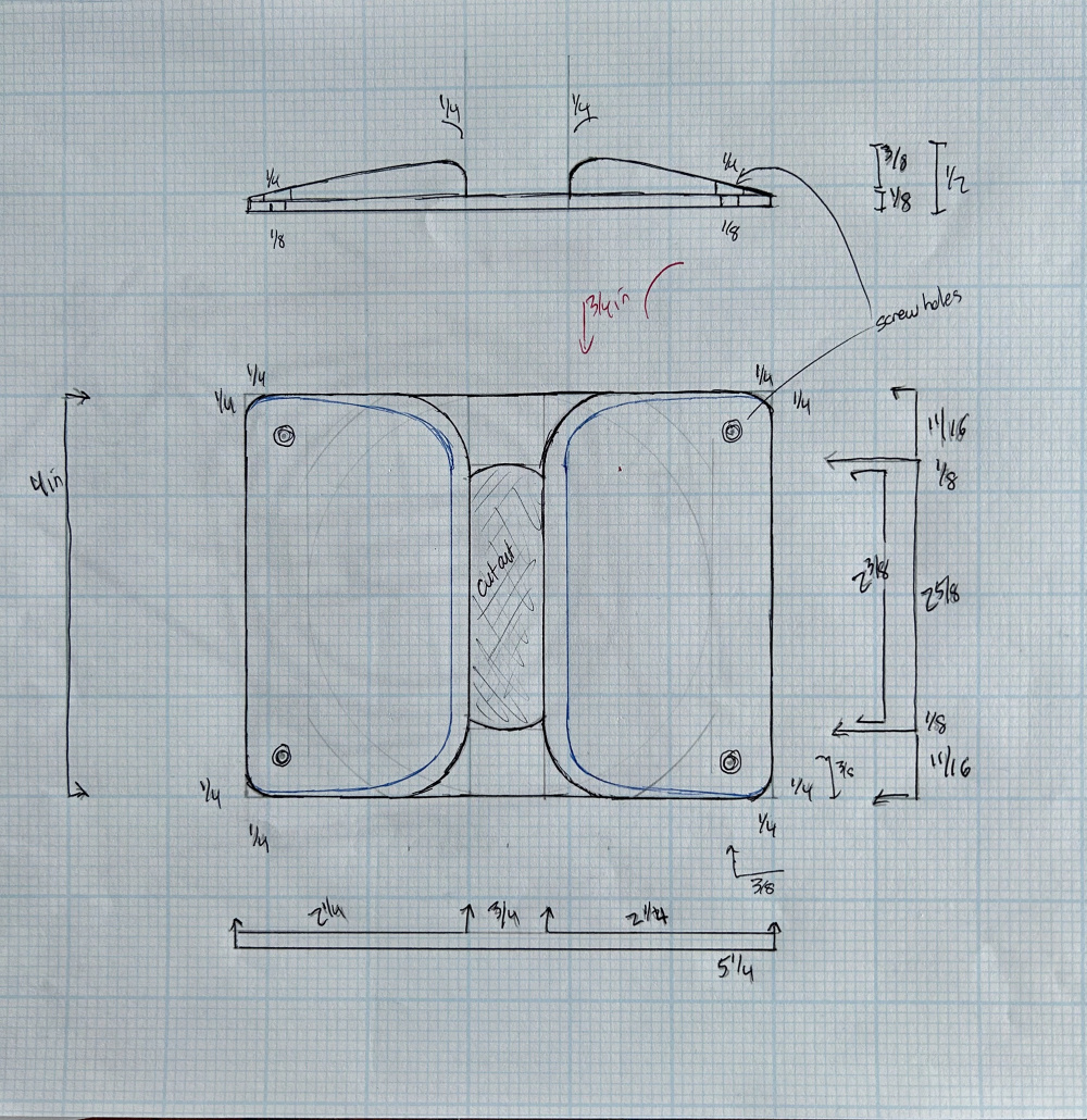
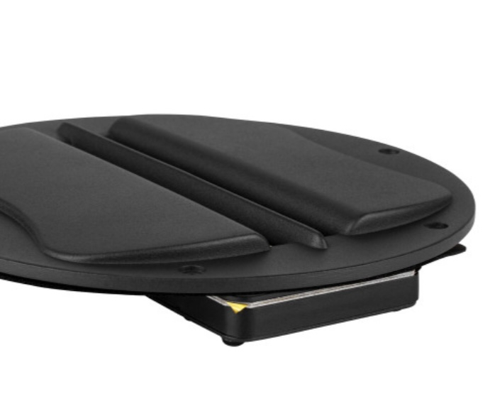
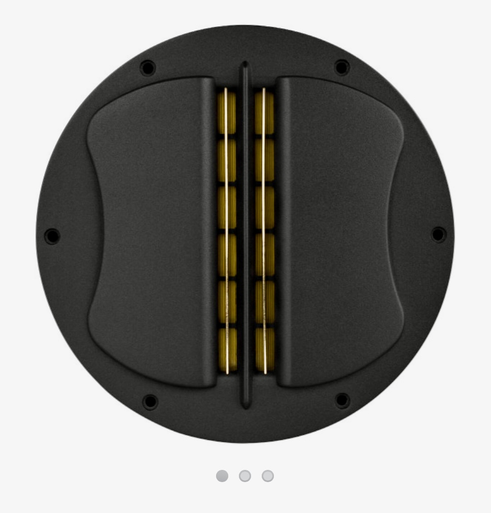
I’d like to try a waveguide idea with the beyma CP21/F slot tweeters for my next project. While I was looking at building them out of wood, clearly 3D prints would be superior. I have drawn and attached my design idea (sorry I do not have CAD experience) for consideration.
Any takers and/or suggestions would be welcome.
Thanks

Comments
I can't really help on the 3d print side, and I know you are trying to get around hand making something.. but at least posting would bump this up and get some more visibility in case the right person didn't see it the first time.
Check out "wm 324" casing from home Depot. The profile and dimensions seem to near perfectly match your measurements if you could get it on a jointer to thin it about half way down.
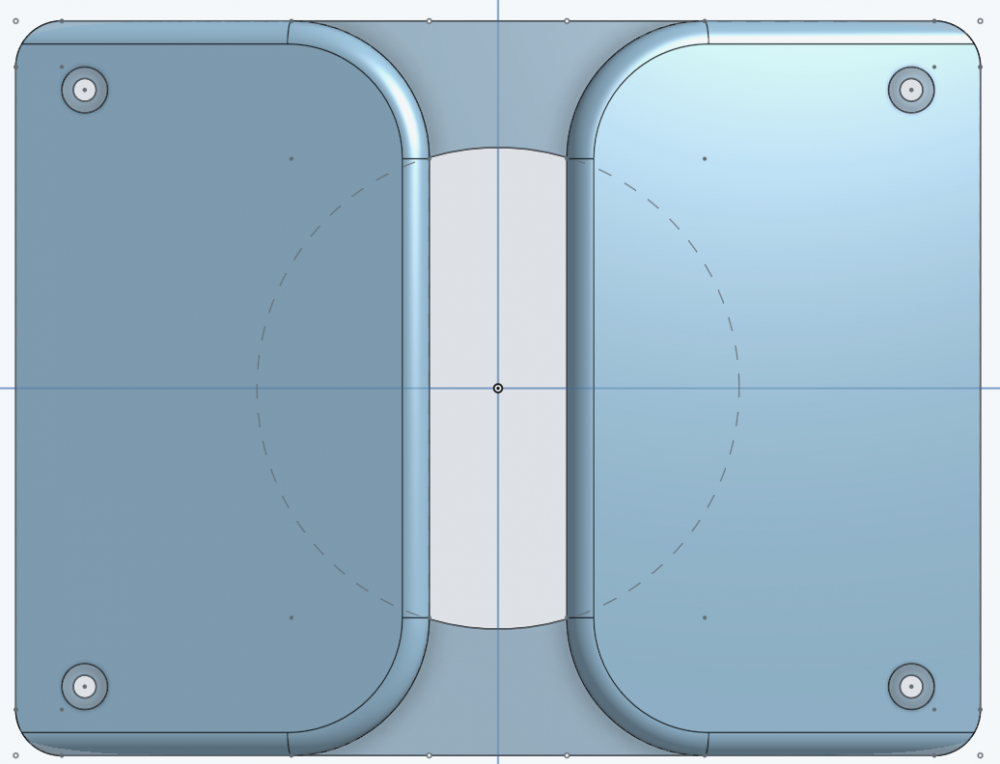
How does this look?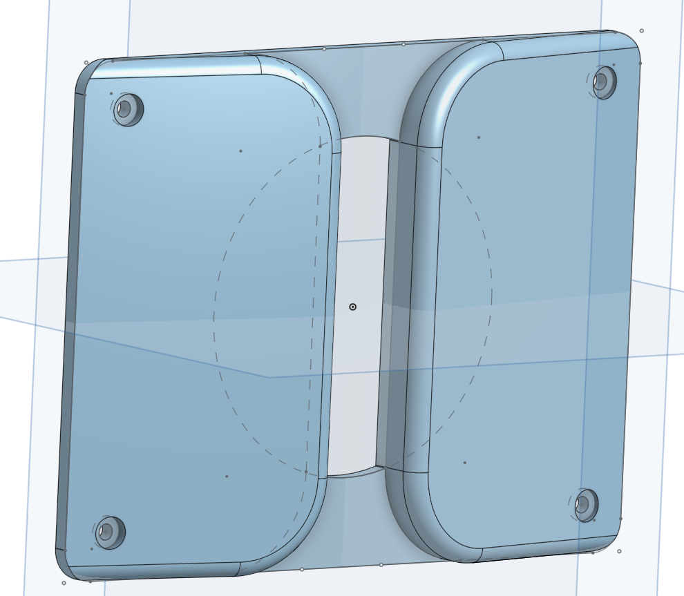
Fantastic ! I've been playing with OnShape for the last hour- and sad to say I've got a rectangle...
I'll drop you a message.
Thanks,
Andy
What software are you using?
I used OnShape") How does the tweeter mount to the waveguide?
How does the tweeter mount to the waveguide?
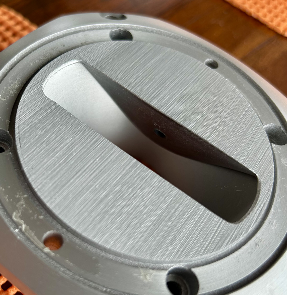
I'm planning on first mounting the tweeter so its top face is flush (or just slightly proud) with the baffle (per its 4 outer ring screw holes), and then mount the waveguide on top to the baffle (per the 4 screw holes you have set into the waveguide- which are outside the tweeter's body). I'll look to use a thin gasket up around the tweeter's slot (maybe a thin layer of caulk).
Since this will be flush mount, I'll add a roundover to the outside. Does there need to be a smoother transition for the Tweeter cut out as well?
Thanks, but I don't think it needs a roundover to the outside, even though it will be a flush mount to the baffle, the felt I place on the baffle will better sit up against it with the straight vertical edges (and I could probably then sand the edges if necessary). Also, keep the cut out to the tweeter slot flat (vertical) as I'll be matching that up directly to the slot (and I can smooth out the fit with the caulk 'gasket').
Ok, I'll try to get you some drawings tonight that will allow you to make sure I created this correctly.
Here you go!
Wow- thanks I’ll take a look
All’s great- but can you make the internal cutout radius 1.282 vs 1.313 (as the diameter is closer to 2 9/16ths).
Thanks
Fixed!
Great job SilverD! I left this page open on my computer thinking I would take a stab at it if I had the time but it looks like the better man got to it first.
Thanks Ken, this wasn't too bad as the shape was simply an extrusion with chamfers and fillets.
The response here at diy.midwestaudio.club has always been helpful, but kudos to these guys !
I’m over-the-top with what SilverD (Nate) has done…if lucky I’d be at extruding my 4 x 5.25 in. rectangle (CAD) at this point.
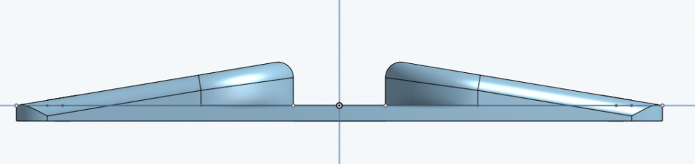
I’m hoping to do something different in my next build with a super tweeter and a ~unique waveguide to blend with the Markaudios. Not to the extent of the JBL Butt Cheeks (but I will include an Lpad) or the Fostex / RatShack Dual Radial Horn Tw. We’ve probably all seen the same image sequence of a sound wave through a slot. If you notice, while it does broaden the path significantly, along the flat surface (past the slot) the wave is not fully controlled. A slot tweeter’s horizontal / vertical propagation are similar (wide horizontal narrow/controlled vertical) to a ribbon / planar, so I drew a bit of ‘inspiration’ from the HiVi Planar.
Looking at that and comparing to the CAD drawing I'm thinking a larger radius may be needed on either side of the slot so the wave can follow it rather than sheering and defracting. but that is feeling more than anything.
The latest has a .250R vs the .125R of the previous CAD.
covered already, sweet
looking real promising!
Both waveguides were printed in PETG, so you should be able to sand them smoother if you like. They were printed with a .8mm nozzle. Going to mail them out soon.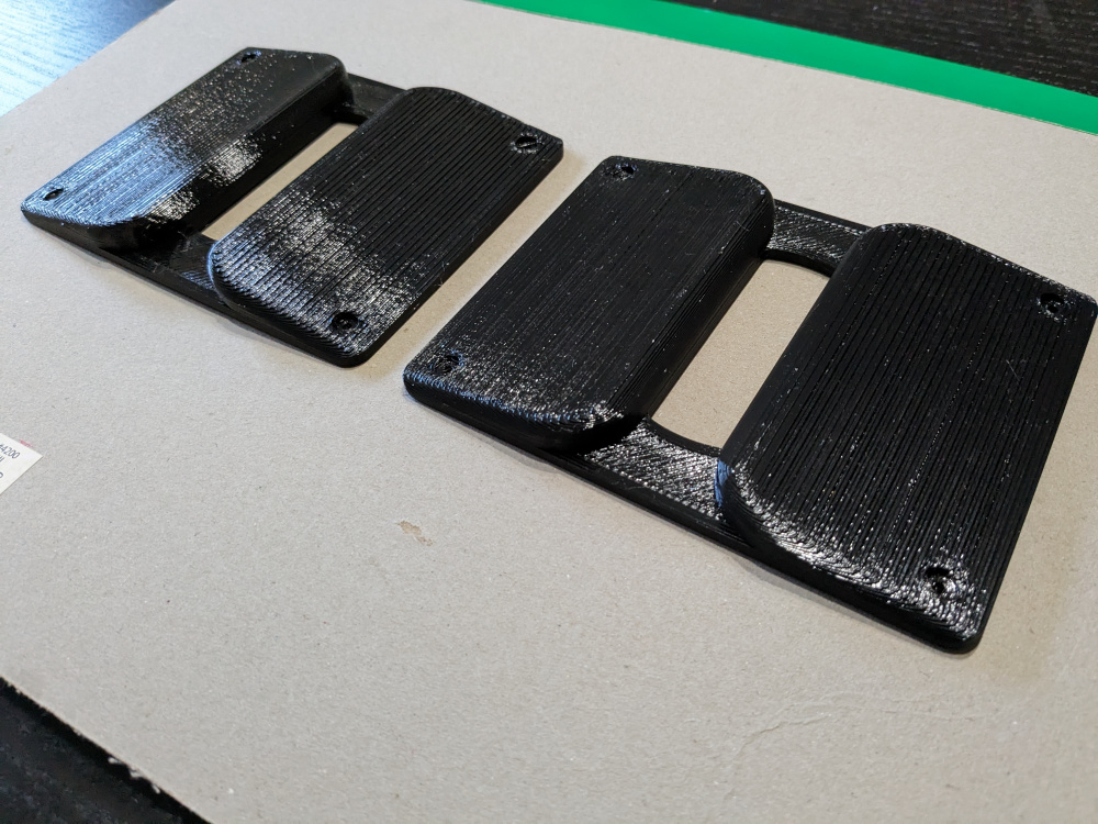
Nate
I’m looking forward to testing/ measuring
THANKS !!!!
I’m thinking I can use a little plastic filler, and lightly sand
That's awesome guys!!
there, I fixed it...
Nate,
Out of the box, these look great !
I'll do a little sanding / finishing and get onto the measurements.
Awesome! Maybe test them out before you put in too much work sanding to see if the overall design works. You could then get much smoother prints made if you want.
Does anything stick to the plastic well enough to work as a filler to lessen the sanding load?
Primer, then spot putty. It really does sand easily though.
With a little patience > first round of sanding waveguide, including a bit of round-over to the vertical sections. The pic is with a first coat of sandable primer, still curing. I have spot putty- but may try an add’l round of primer post sanding.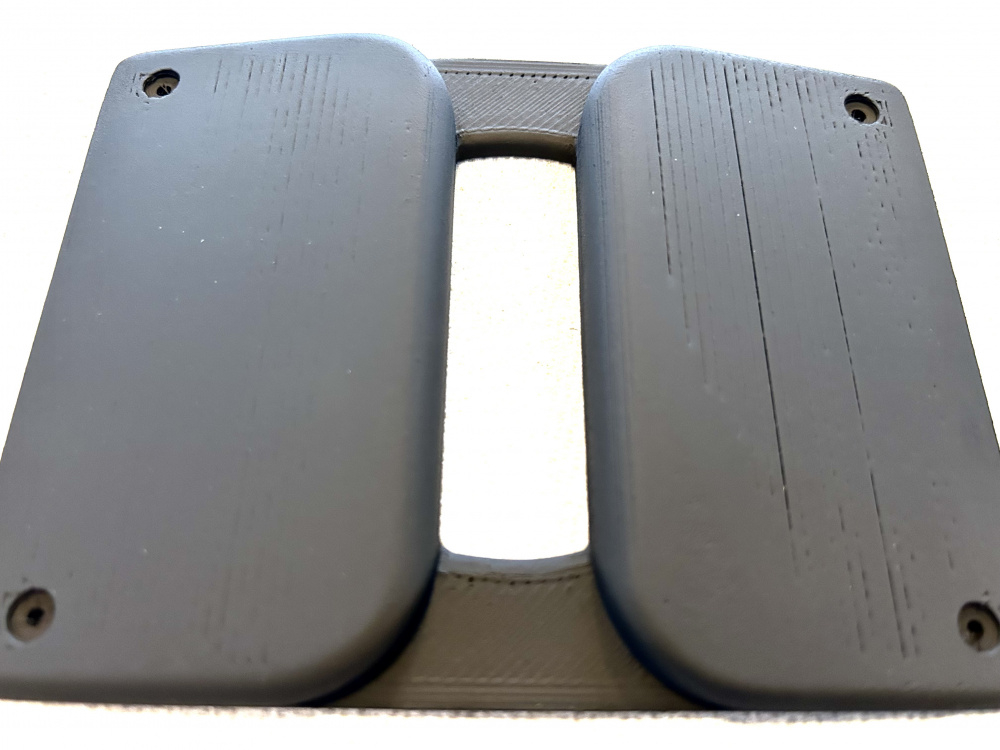
If you have to use MANY coats of primer, it will fill in a portion of the screw hole and make the nice clean circles uneven. Drop some #4 screws in to keep the holes clean from the primer.
…Hopefully I can get some measurements this weekend