Site Links
Howdy, Stranger!
It looks like you're new here. If you want to get involved, click one of these buttons!
Quick Links
Categories
In this Discussion
Who's Online (0)
David's InDIYana 2024 "Inner Sanctum" theme Build.

Hello,
Once again I have decided to throw my hat into the Ring known as InDIYana, and as usual, I don't really know what I am doing.
^The most important part of that is, my Wife has once agreed to drive 6 hours/300 miles across an International border to attend with me.
I must be thicker than the average bear, because I don't think I really understand all the rules, but Ben has said my plans for a coaxial tweeter/mid and pair of midwoofer isobaric style meet the theme criterion, so here we are.
Drivers are,
2x,
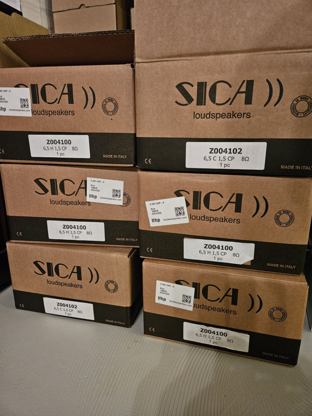
Sica 6,5 C 1,5 CP
Coaxial unit for HiFi and Studio Monitor
Code: Z004102
Nominal overall diameter: 6.5″
Nominal voice coil diameter: LF 1.5″ / HF 1″
Magnet material: LF Ferrite / HF Neodymium
Basket material: Aluminium Die-Cast
Power: 240 W
Sensitivity: LF 91.0 dB / HF 93.9 dB
Frequency range: 55-18000 Hz
4x,
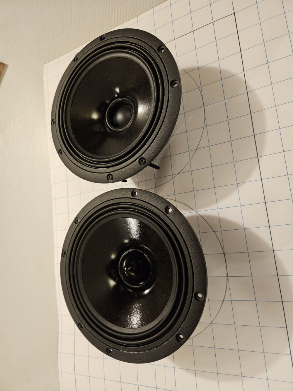
Sica 6,5 H 1,5 CP
Hi-Fi / Studio Monitor
Code: Z004100
Nominal overall diameter: 6.5″
Nominal voice coil diameter: 1.5″
Magnet material: Ferrite
Basket material: Aluminium Die-Cast
Power: 240 W
Sensitivity: 89.4 dB
Frequency range: 40-4500 Hz
There is an overall plan (more of an outline) in my head for what I want to do, but most of the specifics are still to be worked out.
Baffle is to be 1.5" bamboo made from a stock shelf item at a local building centre, edges are going to get a 1.5" roundover, so with the woofers frame being almost 7", that gives me a baffle width of 10-11 inches'ish. Coax and woofer share the same basket dimensions. Coax will be mounted as close to the top of the baffle as possible with no edge treatment on the top edge.
Distance between woofer and coax will be whatever it needs to be. Not sure how much to chamfer backs of the baffle around the woofer for enough breathing room, nor how big the enclosure behind the midwoofer needs to be to attach the second isobaric woofer behind it. These two things will have a lot to do with overall enclosure height, and overall box dimensions cannot be determined until I work these two things out.
Box material will be a semi normal 3/4" Baltic birch box with separate chambers for coax and woofer sections, one solid brace between. Two removable panels on the back to get into box for XO, wiring, port tuning etc.. Veneer sides, either bamboo, walnut or cherry, not sure yet. No translam this year, too expensive, too time consuming and mostly too heavy,
Once I decide on how much the drivers need to breathe, then I can build the isobaric back chamber, then I can design a box around what those need to be. Not very good at planning all this out in advance, just take one step at a time and see where I end up.
My understanding of one of the major drawbacks to Coaxial speakers is intermodulation distortion caused by the woofer surrounding the tweeter, so I hope can limit its extension by crossing it over to the midwoofers beneath it around 400-600Hz. This will be instead of running the woofer coax full range (no high pass) and using the isobaric midwoofers as the .5 in a 2.5. I know sensitivity will take a big hit with this plan, but it's the plan.
Let the building commence,


Comments
Woooo!!
Very interested to see how those SICA coaxials perform sir.
Won't IMD of the coaxials be reduced as the XO Freq increases?
That's the hope...")
Never done a coax, never done an isobaric, never done a three way, lots of firsts here...
First things first, I need to decide how to mount the "inside" woofer, what that is going to look like and how much space it will take up so I can figure out an enclosure size for this project.
Make a sample 1.5" baffle and mount a woofer in it to see what the back of it will look like, then see how much back bevel to give the front woofer so it can "breathe".
First attempt was with a 45º chamfer, but that seemed to generate too big an opening in the 1.5" thick baffle I plan on using, so I tried again with a 30º degree chamfer bit, and that seemed just right.
Now that I know what that looks like, I can make an enclosure that fits behind the front woofer and that the rear woofer can attach to. Just started with some circles 2" bigger than the baffles woofer back bevel opening, cut the same basket clearance hole in them, rebate for the rear woofer to "sit" into the chamber, and then bevel the end that mates to the baffle it to match the bevel on the back of the baffle. Writing this seems so straight forward, yet I spent hours thinking about how to go about this and changed tack a few times as I was going about it.
With the rear woofer mounts done, I can plan for an enclosure...
I look fwd to hearing those drivers, as they have received some huge street cred for a manufacturer.
InDIYana Event Website
Let's hope I can do them justice!")
Did you find a Sica distributor in North America or did you buy them from TLHP?
Bought from TLHP.
Strange, charges for ordering from France or the USA are the same for me.
USA is 75 miles from my house, France is 3800 miles, same shipping, customs, brokerage, taxes, etc. to Canada.
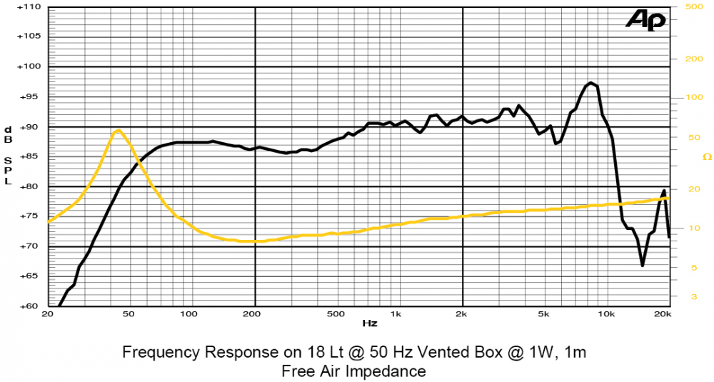
Those certainly look like nice coax units, if that FR graph is legit.
The 5.5" version especially . . .
Has anyone had any luck with the Sica US distributor? About a year ago I contacted the one in Florida that is a car audio installer (seems to me at least) in both English and Spanish and never heard back
Try TLHP in France, their shipping costs are a lot less than I expected. https://en.toutlehautparleur.com/
Enclosure,
Normally I don't worry about driver displacement in my enclosures because I am frequently using 1.5" thick baffles, and by the time I chamfer the back of the baffle to let the woofer breathe, the space "carved out" of the baffle is about what the driver displaces. This time, with the cylinder behind the front woofer, I needed to know what the displacement of that cylinder was and then add bit for the 2nd woofer before figuring out enclosure size. Cylinder is 8-5/8" dia x 2-1/8" thick, or about 2 liters displacement, going to guess under a liter displacement for the 2nd woofer. Before I set out to actually build the iso woofer adapter, I didn't really have an idea what volume it would take up, turns out, in the end, wasn't as big as I thought it might be.
Decided to measure all four woofers raw out of the box, and then after running them for 30 minutes high excursion at 30 hz.
Then run some sims with the three sets of data,
Data not shown for Unibox, 10 watts input power, 2 drive units in parallel, compound, no external components
Going to shoot for 20 liters for woofer enclosure before all deductions like port tube, XO, 2nd woofer, etc.
Time to cut some plywood...
Rated Power measured with 2 hours test with pink noise signal, 6dB crest factor, loudspeaker in free air, power calculated on rated Zmin
Power on Continuous Program is defined as 3 dB greater than the Rated Power
Sensitivity calculated by Thiele and Small parameters, for SPL average in box refer to frequency response
Thiele and Small parameters measured with laser system after preconditioning test
Xmax measured with respect to a THD of 10%
Xvar value corresponding to a decay of the Force Factor, or Compliance, or both, equal to the 50% of the small signal value.
Due to continuing product improvement, the features and the design are subject to change without notice.
It has been a few days since I have posted an update on my InDIYana Iso build, lots of separate parts are being worked on at the same time, but not enough in one area to bother posting about.
The cabinet is starting to come together. It is made from 3/4" Baltic Birch and I am using my standard lock rebate joint to connect the top/middle/bottom to the sides. I just use a 1/8" full kerf 24 tooth flat top grind rip blade as a 1/8" dado blade to made a 1/8"x1/8" grove in the sides and to leave a 1/8"x1/8" tab on the sides to making gluing up easier, things squirm around less. I also break down the glue up, by only gluing one side at a time. It only takes 20 minutes in the clamps, so do one half of one, go do the first half of the other, go back, etc. Makes for less stress if you only have to worry about one side at a time. The grooves for the top and bottom were deliberately made about 1/16" in from the edge of the top and bottom to be flush trimmed off.
Looks like the veneer for this project is going to be walnut, but I don't want to veneer the back, but I also didn't want the rear ply edge showing, and I hate iron on edge banding. Decided to make some solid walnut edging and attach it with the CMT ply edge set.
Lastly, you can see an additional groove all the way around the the inside on the rear of the box, that will be for the bits that the removable back attach to. More on that later...
P.S. Still working on a name for this project...
Precision work
I like the milling for the end grain application. Nice!
Nice looking build.
I've looked at bit sets like that many times but never pulled the trigger worrying that veneered plywood wouldn't hold the angle and I would have a gap. Have you used it with veneered plywood? If so how did it work?
This is the first time I have used it, it is very touchy with regards to cutting a clean sharp edge vs. chipping the edge all up. I wasn't too worried about it in this case though, as the transition from ply to walnut won't be visible.
Part #5,
Today's update couldn't be more boring, it is about the back of the speaker cabinet.
Normally, it would consist of, "I glued the back on".
By why do something so simple, when there are many ways to make it as complicated as possible?
As per my normal, I went the second route.
The back needs to be removable for a couple of reasons, mainly to get the second isobaric woofer installed and wired. Also helps with installing the crossover and port tuning. Simple way would be to use wood screws to install the back, but I went for threaded inserts and furniture screws to hold the back on.
You will have seen the 1/8"x1/8" groove all the way around the inside rear of the cabinet, that was so I could glue in the bits that would make the rear frame the back would attach to.
Furniture screws have a shallow 11/16" dia countersink in the back panels with a 1/4" through hole internally chamfered.
Holes from back panels were transfered to back frame by drilling through back panels, centered with shims.
In order to make sure 1/4" holes were concentrically enlarged to 7/16" for threaded inserts without wandering, a step bit was used to get to the correct diameter, followed by a 7/16" normal drill bit to through drill full depth, holes were also internally chamfered so threaded inserts would sit slightly below the surface.
Took a few iterations to come up with a rear terminal cup bass reflex port layout. Originally in my mind I was going to make a fancy recessed built in terminal cup, but realized wires from XO to rear terminals would have to be attached before the back went on (the wires would be long) since there was no access from the front woofer cut out. Ditched that idea and went with pedestrian 3" diameter premade cups. These would allow me to pass the XO wire out the back with just a little bit of slack to attach to the terminal cup before securing. Terminal cups are attached with #6 button head socket cap screws through to Tee Nuts. Everyone hates Tee-Nuts and has a horror story about them popping off. Securing them with a pair of #4 1/2" screws should make sure that never happens.
I did mix up some 30 minute epoxy and spread alot of it around the large threaded inserts that flowed down into and around their threads, I don't think they will be going anywhere.
Internal block for bass reflex pipe to attach to was glued on, drilled out, flush trimmed to pipe and externally rounded over with a 1" roundover bit.
I can make anything complicated.
Baffle is next...
BTW, am I posting too many pics? I like to see how others build things, I know everyone here knows how to build speakers, but the pics are the fun part for me to look at...
Pics are great! Except when I'm at work where the cell and WiFi are abysmal.
Nice work!
Looks great! You can never post too many pictures.
Built like a tank
Fantastic work !
Your detail of setting up the internal frames for the backs is a teaching piece for me (actually just one of many). And the pics are great.
Can someone remind me how to bookmark this thread?
Time for another tedious update on my Sica iso speaker build,
My plan to use a prefab 1-1/2" bamboo shelf for a baffle fell through when once I started to machine it, the interior was full of random voids. I had already picked up bamboo veneer for the sides as well.
Crap.
What can I do next on short notice that isn't going to cost more money? I have on hand some split live edge walnut and a half sheet of left over Baltic Birch? Translam front and shop made walnut veneer for the sides!
Pics of gluing up translam baffle, laying out baffle, routing in for drivers, attaching second isobaric woofer chamber/holder, installing M4 threaded inserts into the baffle to hold drivers, lapping the box flat on giant sanding block before gluing on baffle, some dowels here and there to things align during glue up so they don't slide around and finally using a solid carbide spiral upcut bit to flush trim the baffle to the box sides.
Next up, Walnut Veneer...
Jealous of the SuperMax drum sander! Those things are awesome, I have access to one at my buddy's shop.
Fine save on the baffle and can't go wrong on some walnut👍🏻
Nice set of pictures. Keep them coming. They tell a very detailed story of how you carefully machined and assembled all the parts that go into an isobarik speaker. Great job.
Yeah, this is fantastic workmanship.
Your attention to detail for even the things that don't show (ie the isobaric rings) is motivating. Great work Sir.