In my very limited experience, it's prob that 180uf dragging down the impedance low and might find not need that big of a value when tweak measuring with components in place. I found myself connecting mid so double sided reverse null then tweaked values to get bass to mid phase matching better by seeing improved rev null happening and would end up going from 100-140uf value I thought needed ending up with 47-80uf.
Interesting to see that off axis for tweet, was always driving me nuts how coax's, at least in the 4-6 inch range, have that 10k on axis dip and seeing it fade away with those off axis shots.
Yo can't have the tweeter circuit like that as you are shorting out the upper treble to the amplifier. You have to have a resistor somewhere in that series path so this doesn't occur.
@Wolf said:
Yo can't have the tweeter circuit like that as you are shorting out the upper treble to the amplifier. You have to have a resistor somewhere in that series path so this doesn't occur.
You could add a small resistor in series with the 2.4 uF cap in that shunt leg. I had to do something very similar in my Rushers project to tame a rising frequency response in the RS28F tweeter. Worked very well.
Just my opinion of course but I also think you need to hammer down that midrange cone breakup some more. Right now it's only -19 dB which can be very audible and it's in a place where our ears are very sensitive. It clearly shows up in the combined FR.
I would not go below 4 ohms if that isnyour amp stability rating. It would be the only resistance between the amp connections. Even then, the tweeter is in parallel with it, so it could need to be higher.
I used a 4 uF cap and 4 ohm resistor but it was a different tweeter. That said my project's impedance never dropped below 4 ohms all the way up to 40 kHz (couldn't measure above that).
Regarding the comments above about the 2.4uf cap in the shunt leg (changed to 1.2uf in the latest image).
Is adding the series resistor out in front of everything (like the picture directly above) what you meant, or like the image below?
I will chime in with my two cents, and then wait for the more experienced to correct me.
Jeff Bagby pointed this exact problem out to me a number of years ago when I would do this on a woofer to supress cone breakup,
Just cannot have positive amp signal passing through caps to ground, will show up as a short, you need resistance somewhere in the path. That is why either what I have done, or what you have shown is correct.
I didn't realize it was the same problem as what I did on the tweeter until Wolf pointed it out.
^
Did I get that right? (I am a slow learner and usually need to be told the same thing several times...)
@DaveFred - in the text from Jeff, does the " .5 uf cap" refer to the " .3 uf cap" in the image?
Because I have done exactly what you have in the red circle, and now I'm nervous. I have seen the resistors after the .3 uf in the image, and never knew what it did.
@a4eaudio said: @DaveFred - in the text from Jeff, does the " .5 uf cap" refer to the " .3 uf cap" in the image?
Because I have done exactly what you have in the red circle, and now I'm nervous. I have seen the resistors after the .3 uf in the image, and never knew what it did.
Yes, I think it was just a typo on Jeffs part, as he was referring to the only two caps in the woofer circuit.
I think it depends on the amp. For testing I am using an Adcom GFA5002 with adjustable gain and I have shut it down with XO mistakes, but never shut it down/blown it up with bad design elements. Same with listening amps, I think some might be more forgiving of a less than ideal design.
Sounds like speaking of the "tank" cap to squash woofer breakup peak. Above that frequency the impedance will come back down. Typically the frequency range where it will get concerning is above 20k. Even if the source material isn't supplying signal that high... The amp will likely still have bandwidth capability. It may depend on how much damping the amp has if it will be excited by the low impedance or not. The resistor will prevent the impedance from getting so low.
For example you can see it in the estimated impedance plots in my 3way build. When I added in the tank cap the blue woofer impedance line goes up off the graph then comes back in until it drops to around 8ohm at 20k. But you can tell it is still going down past that. https://diy.midwestaudio.club/discussion/2380/peerless-based-8-3-way-build/p4
In that thread Ben reports he sometimes uses an electrolytic cap (non polar) in that spot and rely on the esr to handle it enough to keep the amp from riding the lightning.
With the measurements done and some tweaks done to the crossover, it was time to listen to it, tweak a little more and then build them.
Never having really thought about it before, a three way has double the filters of a two way, and with the drivers I am using, it added up to a lot of parts.
Pic of mess on the floor as I try out parts for the XO.
Pics of building a crossover, pretty normal stuff.
Couple shots of speakers all ready to take to InDIYana tomorrow.
David, now that it is finished what do you think of the coax? Its power handling puts it in kind of a unique spot outside of PA drivers. Appreciate your thoughts as the designer and others who listened.
Comments
In my very limited experience, it's prob that 180uf dragging down the impedance low and might find not need that big of a value when tweak measuring with components in place. I found myself connecting mid so double sided reverse null then tweaked values to get bass to mid phase matching better by seeing improved rev null happening and would end up going from 100-140uf value I thought needed ending up with 47-80uf.
Interesting to see that off axis for tweet, was always driving me nuts how coax's, at least in the 4-6 inch range, have that 10k on axis dip and seeing it fade away with those off axis shots.
Yo can't have the tweeter circuit like that as you are shorting out the upper treble to the amplifier. You have to have a resistor somewhere in that series path so this doesn't occur.
InDIYana Event Website
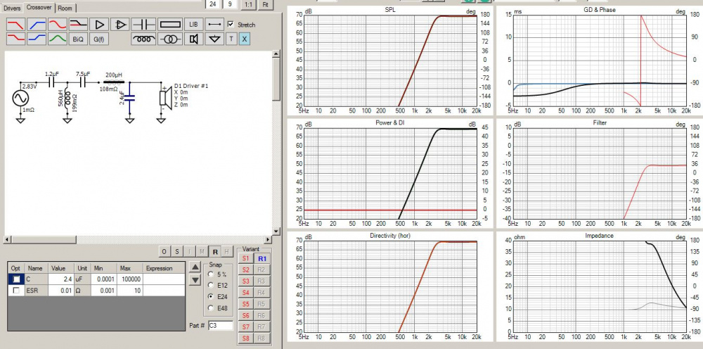
The low pass 2.4uf cap?
Yes. Without an inductor before the cap, the impedance nose dives above 10kHz:
You could add a small resistor in series with the 2.4 uF cap in that shunt leg. I had to do something very similar in my Rushers project to tame a rising frequency response in the RS28F tweeter. Worked very well.
Just my opinion of course but I also think you need to hammer down that midrange cone breakup some more. Right now it's only -19 dB which can be very audible and it's in a place where our ears are very sensitive. It clearly shows up in the combined FR.
How small a resistor do you think I can use in series with the 2.4 cap?
I would not go below 4 ohms if that isnyour amp stability rating. It would be the only resistance between the amp connections. Even then, the tweeter is in parallel with it, so it could need to be higher.
InDIYana Event Website
I used a 4 uF cap and 4 ohm resistor but it was a different tweeter. That said my project's impedance never dropped below 4 ohms all the way up to 40 kHz (couldn't measure above that).
@Wolf
I redid the top end and I think this corrects the problem you were describing.
Going to put this one together and start testing/listening...
@PWRRYD @Wolf
Regarding the comments above about the 2.4uf cap in the shunt leg (changed to 1.2uf in the latest image).
Is adding the series resistor out in front of everything (like the picture directly above) what you meant, or like the image below?
I will chime in with my two cents, and then wait for the more experienced to correct me.
Jeff Bagby pointed this exact problem out to me a number of years ago when I would do this on a woofer to supress cone breakup,
Just cannot have positive amp signal passing through caps to ground, will show up as a short, you need resistance somewhere in the path. That is why either what I have done, or what you have shown is correct.
I didn't realize it was the same problem as what I did on the tweeter until Wolf pointed it out.
^") (I am a slow learner and usually need to be told the same thing several times...)
(I am a slow learner and usually need to be told the same thing several times...)
Did I get that right?
@DaveFred - in the text from Jeff, does the " .5 uf cap" refer to the " .3 uf cap" in the image?
Because I have done exactly what you have in the red circle, and now I'm nervous. I have seen the resistors after the .3 uf in the image, and never knew what it did.
Yes, I think it was just a typo on Jeffs part, as he was referring to the only two caps in the woofer circuit.
I think it depends on the amp. For testing I am using an Adcom GFA5002 with adjustable gain and I have shut it down with XO mistakes, but never shut it down/blown it up with bad design elements. Same with listening amps, I think some might be more forgiving of a less than ideal design.
Sounds like speaking of the "tank" cap to squash woofer breakup peak. Above that frequency the impedance will come back down. Typically the frequency range where it will get concerning is above 20k. Even if the source material isn't supplying signal that high... The amp will likely still have bandwidth capability. It may depend on how much damping the amp has if it will be excited by the low impedance or not. The resistor will prevent the impedance from getting so low.
For example you can see it in the estimated impedance plots in my 3way build. When I added in the tank cap the blue woofer impedance line goes up off the graph then comes back in until it drops to around 8ohm at 20k. But you can tell it is still going down past that.
https://diy.midwestaudio.club/discussion/2380/peerless-based-8-3-way-build/p4
In that thread Ben reports he sometimes uses an electrolytic cap (non polar) in that spot and rely on the esr to handle it enough to keep the amp from riding the lightning.
With the measurements done and some tweaks done to the crossover, it was time to listen to it, tweak a little more and then build them.
Never having really thought about it before, a three way has double the filters of a two way, and with the drivers I am using, it added up to a lot of parts.
Pic of mess on the floor as I try out parts for the XO.
Pics of building a crossover, pretty normal stuff.
Couple shots of speakers all ready to take to InDIYana tomorrow.
Finished with hours to spare....")
See you there!
David.
Distinct and unique appearance to those cabinets - looking forward to the feedback concerning the sound of those Coaxials . . .
Finish was incredible, we were all in wonder of how the baffle was so seamless to the side veneer and everything so perfect
Yup, beautiful build and sounded great!
David, now that it is finished what do you think of the coax? Its power handling puts it in kind of a unique spot outside of PA drivers. Appreciate your thoughts as the designer and others who listened.
This was a great build, the drivers are a really solid deal. Well done!