@Steve_Lee said:
So funneling the mid's back pressure wave down to a smaller enclosure through some light stuffing and then opening the exit of the funnel to a larger cavity sounds like a good possible solution?
Sounds about right to me [logically].
The way I look at it, it splits the energy into multiple resonances due to the different the volume of each chamber, also adding a third resonance for the total volume of both. That way the effect is a reduction in amplitude and smoothed across a wider band. There may be more to it than that.
@Steve_Lee said:
So funneling the mid's back pressure wave down to a smaller enclosure through some light stuffing and then opening the exit of the funnel to a larger cavity sounds like a good possible solution?
Sounds about right to me [logically].
Or a long, tapered, and stuffed transmission line.
@PWRRYD said:
I wonder which of the two or three impedance peaks DATS is using for its Qtc measurement? Do you see corresponding bumps in a near field FR?
My guess is that it is defaulting to the largest peak, but not sure. I will try to make some comparisons to the sharpness of the peak on other graphs that have single peaks. Maybe this will give us a clue as to what the software is actually doing.
I have now taken a bunch of NF measurements, impedance curves, and harmonic distortion tests on several loading formats for the the PS95's. And listened with heavy bass track percussion type music on each one. I'm sifting throught the data and trying to sort it all out. The harmonic distortion data clearly lines up with the impedance curve data. Very revealing. The clear winner is the dual aperiodic lightly stuffed vent arrangement protuding out the sides at two separate locations on a 9" by 1.5" ID lightly stuffed chamber. I used denim ultratouch for stuffing. I'll take some photos and attach a few comparison graphs later today.
The way I look at it, it splits the energy into multiple resonances due to the different the volume of each chamber, also adding a third resonance for the total volume of both. That way the effect is a reduction in amplitude and smoothed across a wider band. There may be more to it than that.
"@Steve_Lee said:
So funneling the mid's back pressure wave down to a smaller enclosure through some light stuffing and then opening the exit of the funnel to a larger cavity sounds like a good possible solution?
Sounds about right to me [logically]."
I think you both are on the right track. Also of note, I am finding that this resonance and distortion control is a "zero sum game" of sorts. In other words, there is only so much energy that can be spread around using this trick. If you use chambers to reduce distortion in one band of frequencies, then the distortion goes back up in another band of frequencies. So you have to "pick your poison" so to speak. Which band of frequencies are the most important? Do you want high distortion in the 20Hz to 80Hz band and low distortion in the 100Hz to 300Hz band? Or do you want lower distortion in the 20Hz to 80Hz band but higher distortion in the 100Hz to 300Hz band? This is the trade off. I am leaning toward lower distortion in the 100Hz to 300Hz band because I think that this will probably be more audible. That is what my ears are telling me.
I'll start out by posting pictures for the 4 configurations for which I saved the impedance curves, NF cone and port frd curves, and harmonic distortion graphs. I did alot of other testing, but I did not save the data because many configurations simply measured or sounded bad, and I did not want to waste time saving everything. I have labeled these as config A, B, C, and D below. I'll place these config letters on each graph, when I post them later, to avoid confusion.
Config A --- The first rear chamber is a 3" to 1.5" ID PVC coupler. Lightly stuffed with Denim. The 2nd rear chamber consists of two 1.5" ID PVC Tee section couplers with side firing 0.75" by 1/2" aperiodic vents. The Tee section couplers and side firing vents are lightly stuffed with denim. The final Tee section is capped off. Total length of the two Tee section couplers is 9"
Config B --- The first rear chamber is a 3" to 1.5" ID PVC coupler. Lightly stuffed with Denim. The 2nd rear chamber consists of two 1.5" ID PVC Tee section couplers with side firing 0.75" by 1/2" vents that are sealed off with c-clamps (I didn't have small PVC plugs handy, need to get some). The Tee section couplers and side firing vents are lightly stuffed with denim. The final Tee section is capped off. Total length of the two Tee section couplers is 9"
Config C --- The rear chamber is a 3" to 1.5" ID PVC coupler. Lightly stuffed with Denim and then capped off.
Config D --- The rear chamber is a 3" to 1.5" ID PVC coupler. Lightly stuffed with Denim. This time the cap is removed, to let the widebander cone go "flapping in the wind." I also tested this without stuffing, but the sound was horrible. Stuffing with denim makes a huge difference in sound quality.
@tajanes said:
Vandersteen uses/ used a transmission-line loaded mid design to “eliminate” backwave reflection. ‘Attenuate’ may be more accurate.
That was always one of the reasons given for transmission lines back in the day. Midrange tonal quality. Dissipation of midrange resonances along the TL line. Slow roll offs with damped impedance curves. Midrange quality seems to be related to the overall magnitude and Q of the impedance curve. Old Speaker Builder articles written by Gary Galo and Duke LeJune made this argument as well. I tried to come up with a transmission line for this project, but so far have been unsuccessful. If I make the cross section too small, using 1/2" PVC pipe, the line does not have a big effect on the cone. I need to use a minimum of 1.5" ID pipe for the line, but then it gets very long with lots of folds that will be difficult to stay within the 1.25 cu ft limit.
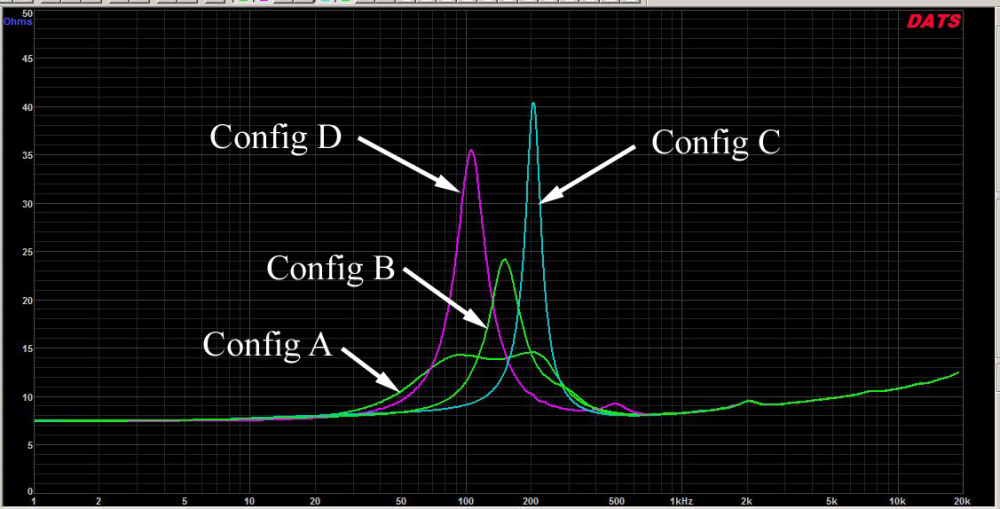
Impedance curves: Note how low the impedance curve is for Config A compared to the others. DATS reports the Qtc as .58, but this is a double hump, so, its probably not quite this low. 2nd place goes to Config B, which is still fairly low and comes in at a Qtc of .84. Then Config D, with a Qtc of .73 and Config C with a Qtc of 1.25.
Here are the distortion graphs. Note that Config A has the lowest distortion from 100 to 300Hz. Config C has much higher distortion from 100 to 300Hz, but has lower distortion that Config A from about 50-90Hz. Config D has the highest distortion from 20 to 40Hz.
Note: The HD measurements were made at a fairly high level, a bit higher than the playback levels used at most events. The SPL levels shown on the graphs should be boosted by 10dB, because Windows always resets the OmniMic volume level to 33% every time I restart the program. The real SPL levels are exactly 10dB higher when the volume is adjusted to 100% in control panel. Mic distance was 15 inches on axis with the PS95-8's.
Yikes, glad I went smaller. I didn't catch that even though I read through it a few times. Guess all the 1.5way talk got 1.5 stuck in my head.
Of your measurements... It is interesting that you can see the effect of each configuration's cone control as a downward slope of the distortion below 100hz. Except Config D, which makes sense.
@6thplanet said:
So is there anything between each "stage" of configuration A?
Nope. A short length of 1.5" ID PVC pipe couples them together. Lightly stuffed with denim ultratouch along the entire 9" length. Looks kind of like a chu chu train with two short, stubby smoke stacks.
I don't see a configuration here that has 2 sealed sections with an aperiodic vent joining them and the driver in one section. This is what I've used more than once before. Stuff the driver section, and line the other, MAPD. Anything from 50/50 to 66.6/33.3 volumes tends to work. The Northcreek literature says front section should be 1/3*Vas and the rear is equal to Vas. You can flip the orientation either way and see what it does.
The aperiodic vents exiting to the outside of the chambers as listed above in ABCD will still unload under a certain frequency. The benefit of the MAPD style is that there is no unloading because the rear chamber is sealed.
As you've shown above, Bill, the version A is a standard aperiodic and suppresses the tuning and the magnitude is much lower. However, it does not shift the the tuning lower. It will still unload below there. It looks as though the chambers are acting as one volume.
C, a small sealed box, will always make the Fs magnitude and frequency increase. This is of no benefit unless the driver is controlled tightly by the air spring.
B reduces the magnitude a little, but not as much as A, and appears to be operating as a damped single volume instead of 2, or this would look alot different in impedance.
D actually is closer to what B should look like in impedance profile, but the aperiodic valve in B is not sealed enough, and D isn't either.
What I'm seeing above is that the adapter that is lightly stuffed is not working as efficiently as an aperiodic exited chamber. The denim should be a solid or cohesive sheet as it comes in the package, and not just a clump of fibers or trimmings. It should also be about a half inch thick minimum. This is very important, because it has to resist the volume of air flowing. This also means that the denim should have a sealed perimeter around the inner orifice of the PVC adapter. E6000 works great here. This makes the slowing more effective as in how a aperiodic valve should be. Once you do that, the effects will be more noticeable. I would actually place the denim matte in the reduction throat, make sure it is oversized to fit snugly, and seal the outer rim and inner rim of the denim to the PVC with E6000. This will not allow the pressure wave to enter a shorter path through the side fibers. Now, if you used a chunk of melamine or open cell foam and cut it oversized and wedged it in the orifice, then your tests would be a lot closer to what you are looking for.
Hope this helps...
Thanks for the analysis, Ben! Good stuff. I'm heading back to Menards today to get some more plumbing fixtures. What you say makes alot of sense. Will give some of your ideas a try and see what happens. I have several sheets of 1/2" thick rigid fiberglass that I can use to form the aperiodic venting. That small amount of denim that I have placed in the small, short smoke stacks actually blows out onto the floor during deep bass percussion events. I was thinking of gluing some screen material over the top to keep it from blowing out onto the floor. Maybe try 1/2 rigid fiberglass. This is the Armstrong pebble 2x4' x 1/2" thick acoustical ceiling fiberglass panel stuff.
@kenrhodes said:
Dayton PS95-8 and the TB W6-1139SIF
I'll start a new thread instead of mucking up Bill's thread... but those are in fact the drivers Bill is using. Mine are completely different drivers. Sorry Bill.
@kenrhodes said:
Dayton PS95-8 and the TB W6-1139SIF
I'll start a new thread instead of mucking up Bill's thread... but those are in fact the drivers Bill is using. Mine are completely different drivers. Sorry Bill.
In addition to impedance and drivers, I'd like to see harmonic distortion plots down to 10Hz or so.
First crossover attempt. Based on a full vertical and horizontal set of 52 measurements. NF/FF/diffraction models were merged together and spliced below 400Hz for both the widebander and the woofer. 9 parts total. Based on the on-axis curve, you may think that it will have a somewhat forward sound from 1-2kHz. However, the in-room response curve is very smooth in this region and yields the highest preference score rating. Impedance curve looks very good, almost 5 ohms and above through the low frequencies, even though I am using a 4 ohm woofer and 8 ohm widebander. The dip in response from about 300 to 700Hz looks a little concerning, so I may revisit this again to see if I cannot fill that in a little bit more. I had one crossover version put together that flattened this out, but then I accidently deleted that version and could not seem to re-create it later on. The extreme high frequency area above 10kHz looks a little choppy, but I don't think there is much I can do about that. This is probably the PS95-8's cone going into breakup mode.
Comments
The way I look at it, it splits the energy into multiple resonances due to the different the volume of each chamber, also adding a third resonance for the total volume of both. That way the effect is a reduction in amplitude and smoothed across a wider band. There may be more to it than that.
I wonder which of the two or three impedance peaks DATS is using for its Qtc measurement? Do you see corresponding bumps in a near field FR?
Or a long, tapered, and stuffed transmission line.
Aww great. Another rabbit hole for me to fall into.
My guess is that it is defaulting to the largest peak, but not sure. I will try to make some comparisons to the sharpness of the peak on other graphs that have single peaks. Maybe this will give us a clue as to what the software is actually doing.
I have now taken a bunch of NF measurements, impedance curves, and harmonic distortion tests on several loading formats for the the PS95's. And listened with heavy bass track percussion type music on each one. I'm sifting throught the data and trying to sort it all out. The harmonic distortion data clearly lines up with the impedance curve data. Very revealing. The clear winner is the dual aperiodic lightly stuffed vent arrangement protuding out the sides at two separate locations on a 9" by 1.5" ID lightly stuffed chamber. I used denim ultratouch for stuffing. I'll take some photos and attach a few comparison graphs later today.
"@Steve_Lee said:
So funneling the mid's back pressure wave down to a smaller enclosure through some light stuffing and then opening the exit of the funnel to a larger cavity sounds like a good possible solution?
Sounds about right to me [logically]."
I think you both are on the right track. Also of note, I am finding that this resonance and distortion control is a "zero sum game" of sorts. In other words, there is only so much energy that can be spread around using this trick. If you use chambers to reduce distortion in one band of frequencies, then the distortion goes back up in another band of frequencies. So you have to "pick your poison" so to speak. Which band of frequencies are the most important? Do you want high distortion in the 20Hz to 80Hz band and low distortion in the 100Hz to 300Hz band? Or do you want lower distortion in the 20Hz to 80Hz band but higher distortion in the 100Hz to 300Hz band? This is the trade off. I am leaning toward lower distortion in the 100Hz to 300Hz band because I think that this will probably be more audible. That is what my ears are telling me.
Paul K did a midrange with a tapered and stuffed TL.
Vandersteen uses/ used a transmission-line loaded mid design to “eliminate” backwave reflection. ‘Attenuate’ may be more accurate.
I'll start out by posting pictures for the 4 configurations for which I saved the impedance curves, NF cone and port frd curves, and harmonic distortion graphs. I did alot of other testing, but I did not save the data because many configurations simply measured or sounded bad, and I did not want to waste time saving everything. I have labeled these as config A, B, C, and D below. I'll place these config letters on each graph, when I post them later, to avoid confusion.
Config A --- The first rear chamber is a 3" to 1.5" ID PVC coupler. Lightly stuffed with Denim. The 2nd rear chamber consists of two 1.5" ID PVC Tee section couplers with side firing 0.75" by 1/2" aperiodic vents. The Tee section couplers and side firing vents are lightly stuffed with denim. The final Tee section is capped off. Total length of the two Tee section couplers is 9"
Config B --- The first rear chamber is a 3" to 1.5" ID PVC coupler. Lightly stuffed with Denim. The 2nd rear chamber consists of two 1.5" ID PVC Tee section couplers with side firing 0.75" by 1/2" vents that are sealed off with c-clamps (I didn't have small PVC plugs handy, need to get some). The Tee section couplers and side firing vents are lightly stuffed with denim. The final Tee section is capped off. Total length of the two Tee section couplers is 9"
Config C --- The rear chamber is a 3" to 1.5" ID PVC coupler. Lightly stuffed with Denim and then capped off.
Config D --- The rear chamber is a 3" to 1.5" ID PVC coupler. Lightly stuffed with Denim. This time the cap is removed, to let the widebander cone go "flapping in the wind." I also tested this without stuffing, but the sound was horrible. Stuffing with denim makes a huge difference in sound quality.
That was always one of the reasons given for transmission lines back in the day. Midrange tonal quality. Dissipation of midrange resonances along the TL line. Slow roll offs with damped impedance curves. Midrange quality seems to be related to the overall magnitude and Q of the impedance curve. Old Speaker Builder articles written by Gary Galo and Duke LeJune made this argument as well. I tried to come up with a transmission line for this project, but so far have been unsuccessful. If I make the cross section too small, using 1/2" PVC pipe, the line does not have a big effect on the cone. I need to use a minimum of 1.5" ID pipe for the line, but then it gets very long with lots of folds that will be difficult to stay within the 1.25 cu ft limit.
Pretty sure the limit is 1.5cf?
Impedance curves: Note how low the impedance curve is for Config A compared to the others. DATS reports the Qtc as .58, but this is a double hump, so, its probably not quite this low. 2nd place goes to Config B, which is still fairly low and comes in at a Qtc of .84. Then Config D, with a Qtc of .73 and Config C with a Qtc of 1.25.
Here are the distortion graphs. Note that Config A has the lowest distortion from 100 to 300Hz. Config C has much higher distortion from 100 to 300Hz, but has lower distortion that Config A from about 50-90Hz. Config D has the highest distortion from 20 to 40Hz.
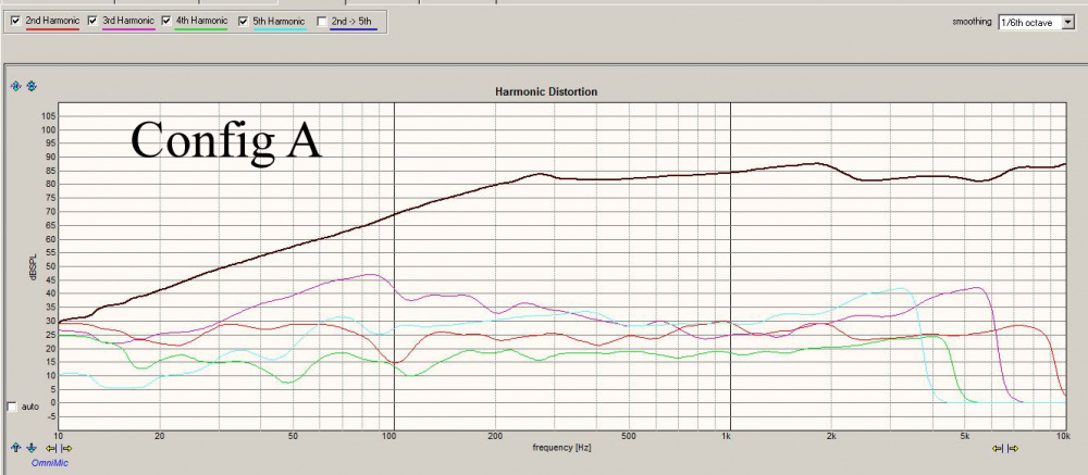
Note: The HD measurements were made at a fairly high level, a bit higher than the playback levels used at most events. The SPL levels shown on the graphs should be boosted by 10dB, because Windows always resets the OmniMic volume level to 33% every time I restart the program. The real SPL levels are exactly 10dB higher when the volume is adjusted to 100% in control panel. Mic distance was 15 inches on axis with the PS95-8's.
Nope. 1.25 or bust.
Yikes, glad I went smaller. I didn't catch that even though I read through it a few times. Guess all the 1.5way talk got 1.5 stuck in my head.
Of your measurements... It is interesting that you can see the effect of each configuration's cone control as a downward slope of the distortion below 100hz. Except Config D, which makes sense.
Dan N did the same on several of his builds
So is there anything between each "stage" of configuration A?
Nope. A short length of 1.5" ID PVC pipe couples them together. Lightly stuffed with denim ultratouch along the entire 9" length. Looks kind of like a chu chu train with two short, stubby smoke stacks.
Interesting project- well documented. Thx
I don't see a configuration here that has 2 sealed sections with an aperiodic vent joining them and the driver in one section. This is what I've used more than once before. Stuff the driver section, and line the other, MAPD. Anything from 50/50 to 66.6/33.3 volumes tends to work. The Northcreek literature says front section should be 1/3*Vas and the rear is equal to Vas. You can flip the orientation either way and see what it does.
The aperiodic vents exiting to the outside of the chambers as listed above in ABCD will still unload under a certain frequency. The benefit of the MAPD style is that there is no unloading because the rear chamber is sealed.
As you've shown above, Bill, the version A is a standard aperiodic and suppresses the tuning and the magnitude is much lower. However, it does not shift the the tuning lower. It will still unload below there. It looks as though the chambers are acting as one volume.
C, a small sealed box, will always make the Fs magnitude and frequency increase. This is of no benefit unless the driver is controlled tightly by the air spring.
B reduces the magnitude a little, but not as much as A, and appears to be operating as a damped single volume instead of 2, or this would look alot different in impedance.
D actually is closer to what B should look like in impedance profile, but the aperiodic valve in B is not sealed enough, and D isn't either.
What I'm seeing above is that the adapter that is lightly stuffed is not working as efficiently as an aperiodic exited chamber. The denim should be a solid or cohesive sheet as it comes in the package, and not just a clump of fibers or trimmings. It should also be about a half inch thick minimum. This is very important, because it has to resist the volume of air flowing. This also means that the denim should have a sealed perimeter around the inner orifice of the PVC adapter. E6000 works great here. This makes the slowing more effective as in how a aperiodic valve should be. Once you do that, the effects will be more noticeable. I would actually place the denim matte in the reduction throat, make sure it is oversized to fit snugly, and seal the outer rim and inner rim of the denim to the PVC with E6000. This will not allow the pressure wave to enter a shorter path through the side fibers. Now, if you used a chunk of melamine or open cell foam and cut it oversized and wedged it in the orifice, then your tests would be a lot closer to what you are looking for.
Hope this helps...
InDIYana Event Website
Thanks for the analysis, Ben! Good stuff. I'm heading back to Menards today to get some more plumbing fixtures. What you say makes alot of sense. Will give some of your ideas a try and see what happens. I have several sheets of 1/2" thick rigid fiberglass that I can use to form the aperiodic venting. That small amount of denim that I have placed in the small, short smoke stacks actually blows out onto the floor during deep bass percussion events. I was thinking of gluing some screen material over the top to keep it from blowing out onto the floor. Maybe try 1/2 rigid fiberglass. This is the Armstrong pebble 2x4' x 1/2" thick acoustical ceiling fiberglass panel stuff.
Not that anyone cares much but here is the final impedance sweep of both speakers for my Indy 2025 theme entry:
Hard to see both because they are so similar. Never drops below 4 ohms.
I may have missed it, but have you said what drivers you are using?
Dayton PS95-8 and the TB W6-1139SIF
I'll start a new thread instead of mucking up Bill's thread... but those are in fact the drivers Bill is using. Mine are completely different drivers. Sorry Bill.
In addition to impedance and drivers, I'd like to see harmonic distortion plots down to 10Hz or so.
They're not too pretty but the speakers still sound pretty good.
First crossover attempt. Based on a full vertical and horizontal set of 52 measurements. NF/FF/diffraction models were merged together and spliced below 400Hz for both the widebander and the woofer. 9 parts total. Based on the on-axis curve, you may think that it will have a somewhat forward sound from 1-2kHz. However, the in-room response curve is very smooth in this region and yields the highest preference score rating. Impedance curve looks very good, almost 5 ohms and above through the low frequencies, even though I am using a 4 ohm woofer and 8 ohm widebander. The dip in response from about 300 to 700Hz looks a little concerning, so I may revisit this again to see if I cannot fill that in a little bit more. I had one crossover version put together that flattened this out, but then I accidently deleted that version and could not seem to re-create it later on. The extreme high frequency area above 10kHz looks a little choppy, but I don't think there is much I can do about that. This is probably the PS95-8's cone going into breakup mode.