Site Links
Howdy, Stranger!
It looks like you're new here. If you want to get involved, click one of these buttons!
Quick Links
Categories
In this Discussion
Who's Online (0)
Micro Grand Utopia
Merry Chirstmas everyone. I've been working on this project for a couple months now, but haven't posted anything yet because I was not sure if it would really work. I now have one prototype cabinet constructed and have taken a set of preliminary "proof of concept" measurements. The graphs look pretty good, so I decided to go ahead and start a build thread.
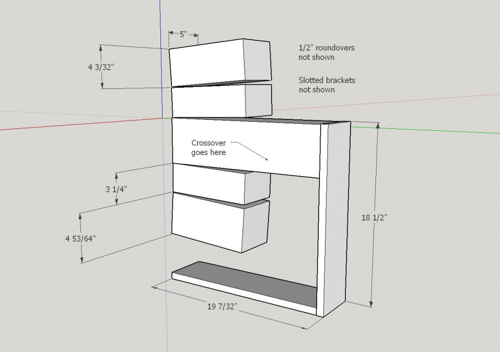
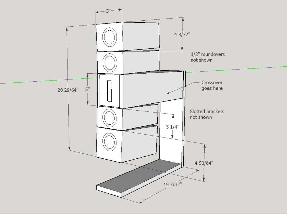
Each channel consists of five independent cabinets arranged in an adjustable curvilinear array. From top to bottom, the layout is "MMTMM" + sub (see drawings below).
Each midrange and tweeter driver is given its own small cabinet and each small cabinet is, in turn, connected to the other small cabinets using slotted masonite brackets. This makes it possible to adjust the relative position of each driver in the "X" and/or "Z" dimensions based on measurements and listening tests.
I initially plan to use very short 2 and 3 inch long slotted masonite brackets that will allow for very small driver micro adjustments. These small adjustments will be somewhat similar in concept to those used by Focal's Grande Utopia or Wilson's WAMM Master Chronosonic loudspeakers. If larger adjustments are needed, I can simply swap out brackets of different lengths.
INITIAL DRIVER SELECTION:
Tweeter: Bozhen CQ76B ribbon (1 per channel).
Midrange: Tectonic TEBM46C20N-4B BMR's (4 of them per channel).
Woofers: GRS 12SW-4HE (1 per channel).
Crossover targets: T/mid: 1-3kHz passive LR2.
Mid/woof low pass: Plate amp set to 150 to 200Hz.
Mid/woofer high pass: 150 to 200Hz passive LR2 with parallel notch to dampen the impedance peak.


Comments
I put together a list of my design goals & methods:
1) Portability goal: Keep the size and weight of the speaker low to save my back when loading and unloading at DIY events.
2) "Swapability" goal: Make it simple to swap out drivers in the middle of the build without having to scrap the entire project and start over. With this multi-cabinet scheme, it should be fairly easy to swap out tweeters or midrange drivers by simply rebuilding or replacing just two small cabs or baffle boards.
3) Directivity goal: Use several small diameter midrange drivers with directivity similar to the tweeter. Attempt to solve the "tweeter-beaming-above-10kHz" problem by designing for a flat response at roughly 20 degrees off axis.
4) Time alignment goal: Evaluate the effect of proper time alignment by arranging the cabs in a curved linear array. Independently move the tweeter and/or midrange cabinets, along the "X" and "Z" axes, to achieve the best possible integration at the listening position. Experiment with "feathering" the vertical "toe-in" and/or driver spacing distances to achieve the best possible imaging. Stop experimenting when I come up with something that measures and sounds good.
5) Measureability goal: Design the enclosure shape to make it easy to capture both vertical and horizontal spin measurements at a height of about 50 inches above the floor. Accomplish this by extending the depth of the 5x5" tweeter cabinet out to 18.5" and then use this extension to flip and clamp the array in either a horizontal or vertical position.
6) 150Hz mid/woofer xover goal: Develop a very low 2nd order high pass midrange xover using a passive parallel notch filter that provides the full 6dB of BSC. Tweak this notch so that it also suppresses the large midrange impedance peak and keeps the overall impedance well above 4 ohms.
7) Frugality goal. Use inexpensive 3/4" thick laminated "value shelving" for all panels. Use relatively inexpensive drivers that measure and sound good. Make inexpensive masonite brackets to screw all the cabs together.
I found my GRS 12 to be pretty noisy when played that high.
Where are the woofers going.
Maybe I will have to swap over to my pair of TB W6-1139SIF subs. The TEM46's won't go lower than about 150Hz.
Directly below each one. The two sub cabs will be 25" high, which will place the tweeters about 41" above the floor.
Here are a few construction pics from the past few months:
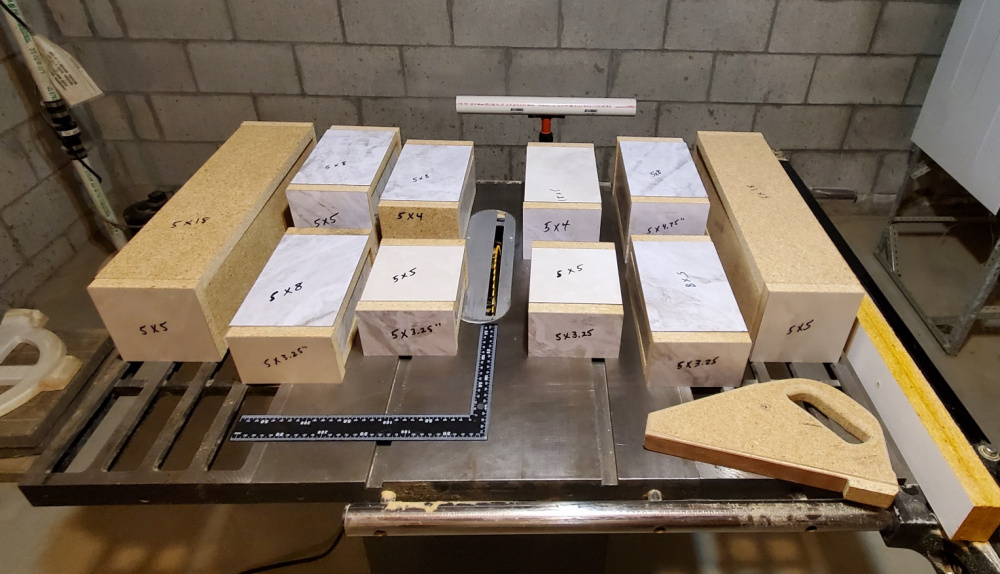
Making all the boxes for two channels:
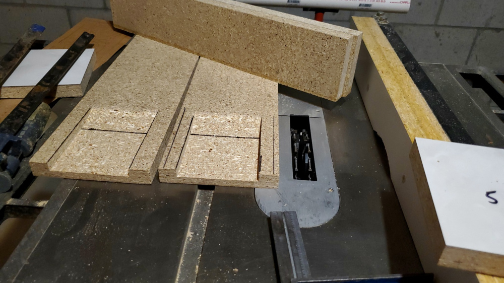
The tweeter baffle is only 5x5" so I needed to cut clearance dados for the Bozhen CQ76B plastic enclosures:
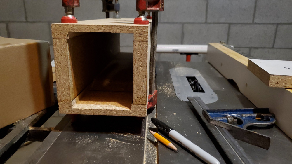
Routing the tweeter flange:

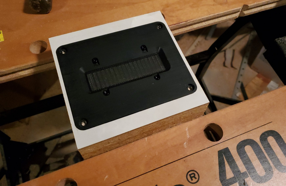
Routing the TE TEBM46 flanges:
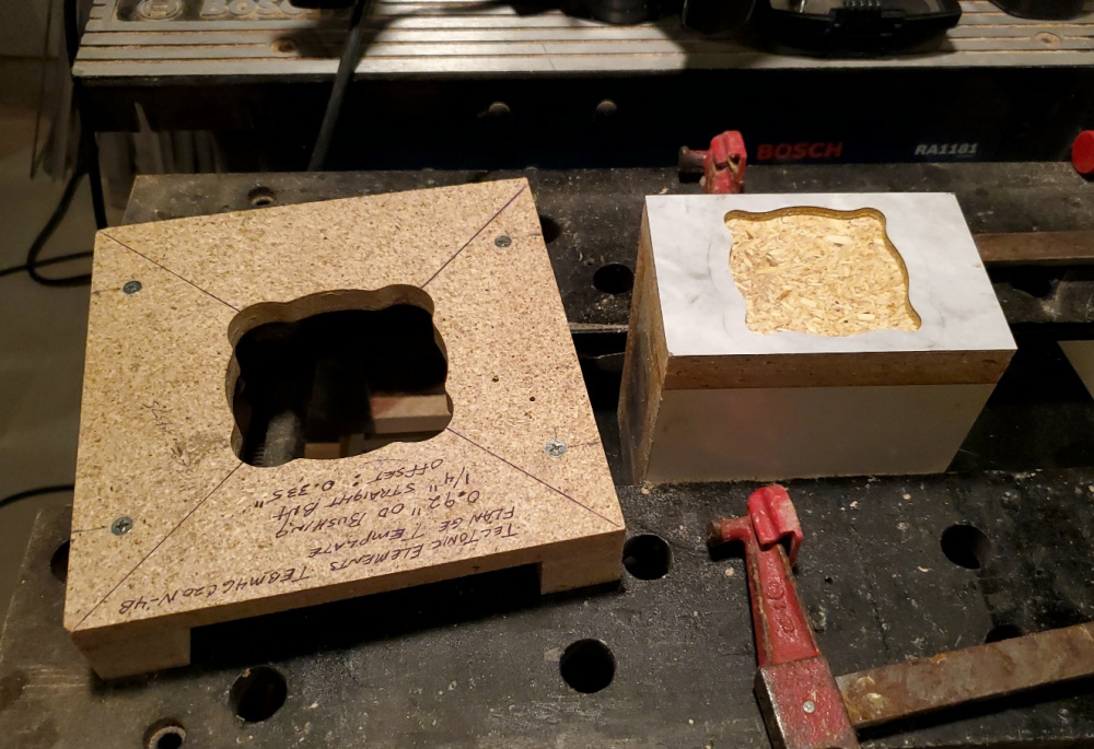
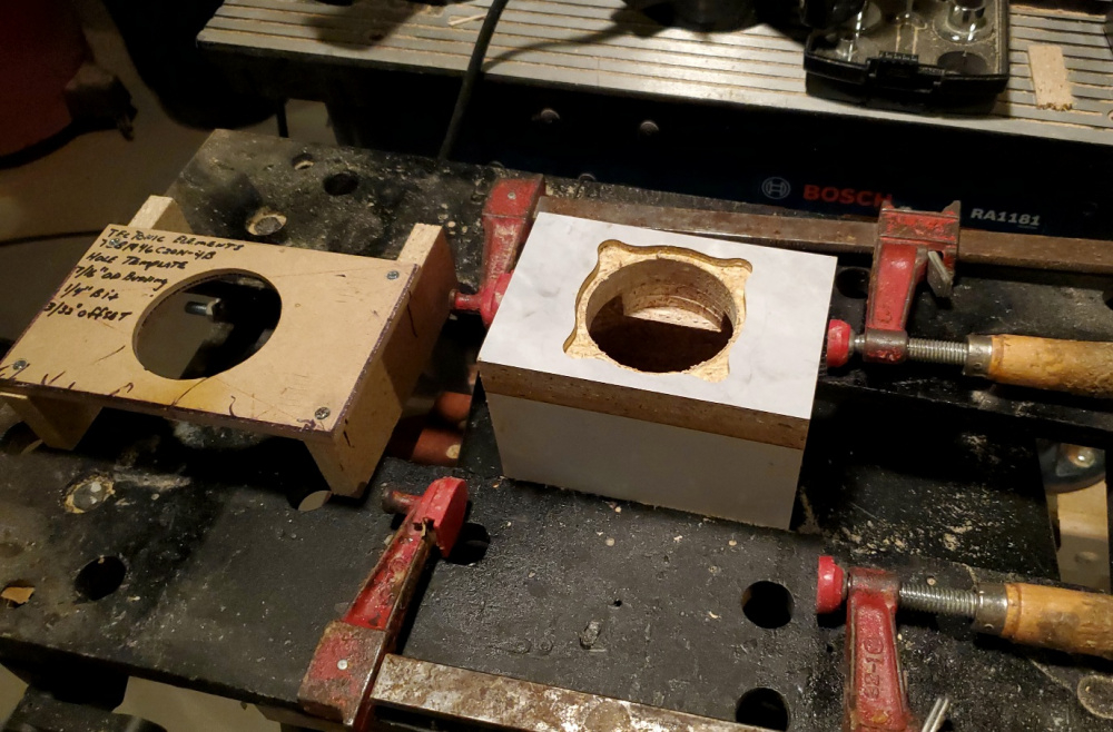
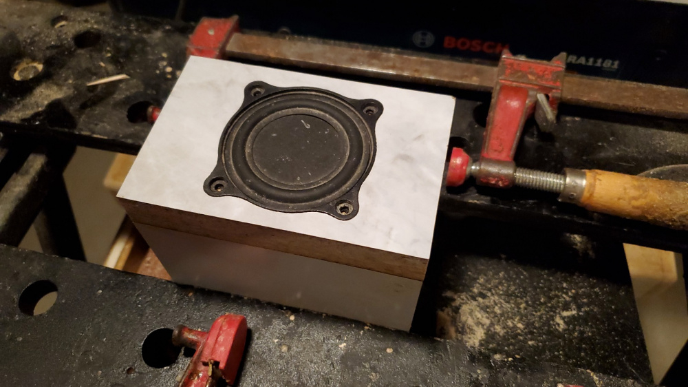
Flange routing done for all 5 boxes:

Boxes screwed together using slotted masonite brackets:
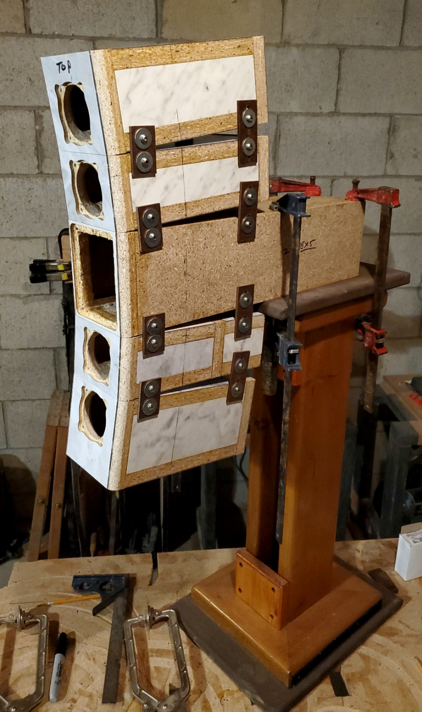
I mounted all drivers and did some measurements yesterday. Will post a few more pics and graphs as I go along.
WoW!
I've been kicking around a similar idea as a kind of "final hurrah" build, one intended to be my last entry into serious design work. Convincing wife to let me spend four or five grand is a different story.
Yeah, slowly gearing up for "one last build" for myself. Everything I've learned. using the best drivers on my shelves.
Just an idea, what if you used 10-32 screws and a bracket in the rear of each box/section for a precise angle adjustment. One full turn would give a 1/32" adjustment.
This will not be my last build, but I am definitely going for a serious "high end" type sound quality on this one. High end sound quality on a beer budget, so to speak.
Good idea. Once I get the other set of cabinets done, I will look into adding this feature. Right now I have to set the entire set of boxes on their sides and then manually adjust the cabinet spacing.
I have been working on the crossover for several days now. I've run into a directivity mismatch snag that I was not anticipating, but I think I have found a solution. The directivity of the tweeter and mids match well in the horizontal domain, but the verticals are another story. I've done some testing which indicates that the solution is to go with a 3.5 way instead of a standard 3 way design. This will involve rolling off the outer two midrange drivers before they have a chance to mess up the power response.
Also, I put together a better drawing, showing how the entire system with subs will look like. I will be using stereo subs with two Dayton SPA-250 plate amps. Have not decided if I will be using my dual TB-W6-1139SIF's per side or building a new pair of cabinets to house just one GRS 12 per side.
Spent a few hours working on the crossover this afternoon. My idea on fixing the directivity problem did not work out, so I think I will simply leave the problem alone and order parts. Below are a couple screen shots showing the problem. The midrange to tweeter crossover is at 1.3kHz. The directivity index peaks up at 850Hz and then levels off as the midrange drivers hand off to the tweeter (see 1st screen shot below). If I load just the horizontal polar data in VituixCAD, the directivity mismatch problem completely disappears (see 2nd screen shot below). But if I re-load the complete horizontal and vertical polar frd dataset, the problem comes back. My conclusion therefore is that this problem is being created by the vertical separation of the midrange drivers. Going from 3 way to 3.5 way has little impact on the directivity curves. I would need to change to different drivers, driver positions, or baffle board dimensions to significantly impact this problem.
Power & DI screen with both horizontal AND vertical polar data loaded into the midrange driver tab:
Power & DI screen with ONLY horizontal polar data loaded into the midrange driver tab:
So then I tweaked parts values around a little bit more and came up with the screen shot below. I think I will go with this one. Not too bad.
Here is what the 6 pack screen looks like. Please note that the reference angle is 20 degrees horizontal, so the speakers are designed to point straight forward, not toed-in toward the listener. If toed-in toward the listener, they will probably sound bright. Crossovers are 172Hz and 1.3kHz.
In the crossover pane you have 1 midrange with zero Y-offset. How is VituixCAD simulating the vertical output without knowing the positions of all 4 midranges?
The reason I ask, is that I was thinking you could play around with the Y-offsets to see what that does, I believe the basis for Kimmo's rule of thumb for C-t-C of 1.2-1.4 x wavelength at the crossover is all about improved vertical and power response. But I noticed you have Y-offset of zero so not sure now you would go about it.
To make things easier to measure, I took all measurements with the microphone 1 meter on axis with the tweeter. I treated the 4 midrange drivers as a single driver for measurement purposes. So I took 13 measurements from 0 to 180 horizontal, then flipped the cabinet sideways and took 13 measurements from 0 to 180 degrees for the verticals. Did the same thing for the tweeter. Took 13 measurements from 0 to 180 horizontal, flipped the cabinet sideways and then took 13 measurements vertical. The microphone tip stayed in the same position for all measurements. Thus the X, Y, and Z values must be zero for all drivers. For the midrange zma I measured them "in-box" wired in series/parallel. Then I took a NF measurement of one midrange, created a diffraction model for the midrange and merged it with the 26 far field polar frds.
PS: I was initially thinking about measuring each driver separately but I simply had to find a way to make this easier. Even so, I ended up taking 52 measurements. If I had done this one driver at a time with Y offsets, that would have been a grand total of 130 measurements! And I have to walk back and forth from my laptop desk to my polar table to manually rotate the speaker for each measurement!
Yes, I completely understand that tradeoff.
The advantage of taking the midrange measurement on axis (even if just one of the midranges) is that you can change the Y-offset and see what it does. My understanding (which very well could be wrong) is that if you take the midrange measurement on the tweeter axis and set Y-offset to zero it is fine for xo work in that situation, but the simulation of changes in Y-offset won't be correct. If you make a cabinet and it is final, then this all works fine. But if you are prototyping and willing to change driver locations on the baffle, then the on-axis measurements give you that flexibility.
Thanks for pointing this out, David. Yes, I think you are correct. The full set of 130 is probably the way to go. I still have the cabs clamped onto my polar table, so I'll give this a go tomorrow.
>
Just so that I am clear on how to interpret this rule, would this be 1.2-1.4x of a full wavelength? Or would it be 1.2-1.4x of 1/2 wavelength? I currently have no gaps between the midrange cabinets, so the C-t-C distance from the tweeter to one of the inner midrange drivers is about 4 inches. The C-t-C distance from the tweeter to one of the outer midrange drivers is about 7.5 inches. This comes out to an average C-t-C spacing distance of about 5.75 inches. Crossover is 1.3kHz. So, if this rule is a full wavelength, I would need to increase the average spacing distance from 5.75 inches out to a minimum of 12.5 inches. This would be an increase of 6.75 inches, which would give me a gap of about 1.68 inches between each cabinet. Does that sound right?
I think the rule of thumb is full wavelength and isn't going to make any sense given your very low xo point. I also don't know if it applies to an MTM arrangement which has a very different vertical radiation pattern from a TM. My guess is that it does NOT apply.
But my thinking is, that you have a simulated problem that appears related to vertical directivity but you haven't simulated the vertical direction accurately. So, it is not clear that you even have a problem to try to fix. A fairly simple approach would be to just take 13 horizontal measurements on the midrange axis and mirror them to vertical. Now you can place two or four of them in vituixCAD and specify all of the Y-offsets and see (1) do you even have a problem and (2) you can play around with the Y-offsets to see if it makes a difference.
By the way, while you are focused on directivity and not impedance, you can right-click on the Impedance pane and select Directivity chart and you will have Horizontal directivity to the left and Vertical to the right and not have to toggle back and forth between hor and ver in just the bottom left pane.
Thanks for the simple 13 measurement approach idea. That sounds like a plan. Will give it a try and see what happens.
I re-measured one midrange driver on my prototype speaker using your simplified 13 measurement suggestion. I also re-measured the tweeter again, both horizontally and vertically (another 26 measurements), because I needed to keep the playback levels exactly the same for all measurements. Note that the tweeter is using actual vertical measurement data instead of data mirrored from the horizontals. This is necessary because the ribbon is not a circular shaped driver. But for the midrange, the mirroring technique works because the drivers are circular and have uniform vertical and horizontal radiation.
Once I had all the data loaded into VituixCAD, I did a comparison between two different midrange driver C-t-C spacing distances. Crossover frequency was 1.3kHz for all comparisons. I compared a spacing distance of 0.56x the crossover frequency to 1.27x the crossover frequency.
Below is the Power & DI screen shot for the 0.56x spacing distance. Y offset values were 190mm, 108mm, -108mm, and -190mm for the 4 midrange drivers. This is the spacing distance with no vertical gap between any of the driver cabinets, which is what I used for the measurements posted previously. Note the peak in the directivity index that occurs at approximately 800Hz. This is related to the crossover frequency of 1.3kHz, as the midrange drivers hand over to the tweeter:
For comparison, here is the Power & DI screen shot for the 1.27x spacing distance. Y offset values were 450mm, 225mm, -225mm, and -450mm for the 4 midrange drivers. Note that the directivity mismatch around 1khz is slightly improved, with less peaking near 800Hz. But this is a huge boost in spacing distance.
When you boost the spacing distance between drivers, however, the vertical lobe narrows significantly at the xover frequency. Here is the vertical lobe at 1.3kHz for the 0.56x spacing distance:
And here is the vertical lobe at 1.3KHz for the 1.27x spacing distance:
This narrow lobe will probably create a difference in midrange tonal balance between a seated and standing listening position. I suppose I could raise the xover up to 2.5kHz or so to reduce the spacing distance required, but I'm not sure what would happen to the lobing problem. Would it go away or actually get worse? Also, one of the big selling points for this driver was the ability to cross very low and still get that high end ribbon sound quality (ie., RAAL). So, at this point, I am leaning toward keeping the 1.3kHz crossover with 0.56x spacing. At least for now. Unless someone can see another option or an error in my thinking.
Here is the revised 6 pack, showing the midrange driver breakouts and Y values for the 0.56x spacing option:
When you get to actually listening critically, if it sounds good, I'm not sure there is any reason to change.
BUT...just because it CAN crossover that low doesn't mean it needs to. Rick Craig used the Bozhen tweeters in a lot of his designs. His Purezza (with the Q76B and Purifi 6.5) was reviewed by Erin and did great...he has raw driver measurements and it looks like it is crossed over around 2.4kHz.
With no vertical gap between cabinets, the average midrange spacing distance is 5.875 inches. This comes out to a full wavelength at 2308Hz. So a 2.7kHz xover would be 1.2x. I'll work up a new xover tomorrow and see what that looks like in terms of directivity and vertical lobing.
I think that since the design is time aligned to one point you should give that priority and not worry too much about vertical lobing.
Bill do you you enable the min. phase calc. by checking the box in the drivers screen in V cad? I am not sure if I should be doing this.
No. I use the raw, as measured phase data for everything. Using minimum phase would introduce more error into the Vcad calculations. I am using a dual channel measurement mic, which gives me more accurate polar response curve summations in Vcad. With OmniMic, you will get accurate on axis curves (using the 3 measurement offset process) using the raw, as measured phase data. But when you add polar measurements you will introduce a certain amount of error because the 3 measurement offset process only corrects the phase for the on-axis set of curves. This single offset calculation, therefore, will not be entirely accurate for off-axis measurements. I have done side-by-side comparisons, dual channel mic verses single channel OmniMic, to actually see the amount of error that is introduced.
Thanks Bill, You da man
I adjusted the tweeter to midrange crossover up to 2.7kHz in my model and then tested it with various Y offset center-to-center (C-t-C) midrange spacing distances. Here is what I discovered:
1) With the smallest average spacing distance of 5.875 inches (equal to 1.2x), there is a slight improvement in the directivity index in the 1.5 to 3kHz frequency range. The directivity peaking at approx 800Hz, however, is completely unchanged. This makes sense because the directivity change is related to the frequency at which one driver hands off the other. In addition, the vertical lobe in the 2kHz to 2.7kHz region is now much narrowing than it was with the lower 1.3kHz crossover. This also makes sense, because as you increase the xover frequency the wavelength shortens and begins to cancel or interfere at this shorter spacing distance. As a result, I'd probably here a tonal balance shift between a seated and standing listening position with a 2.7kHz xover spaced at 5.875 inches.
2) I also tested the 2.7kHz crossover at a variety of wider spacing distances and discovered pretty much the same thing. A slight improvement in directivity smoothness at the cost of vertical lobe narrowing just below the crossover frequency.
I think its time to order parts and give these a listen. Right about now, I really wish I had my EQ/APO system up and running. I have the soundcard, cables and multiple amps in position, but I ran into some problems with the EQ/APO software "locking up" on my laptop. I haven't had the time to debug and solve the problem yet. But if I could get this running, I could export these crossover filter variations to EQ/APO and then give each one a listen without ordering parts. So I really need to get going on that project. See link below:
https://diy.midwestaudio.club/discussion/comment/37340#Comment_37340