Site Links
Howdy, Stranger!
It looks like you're new here. If you want to get involved, click one of these buttons!
Quick Links
Categories
In this Discussion
Who's Online (0)
XO Design for MDF MCM MTM
XO design for the MCM MTM.
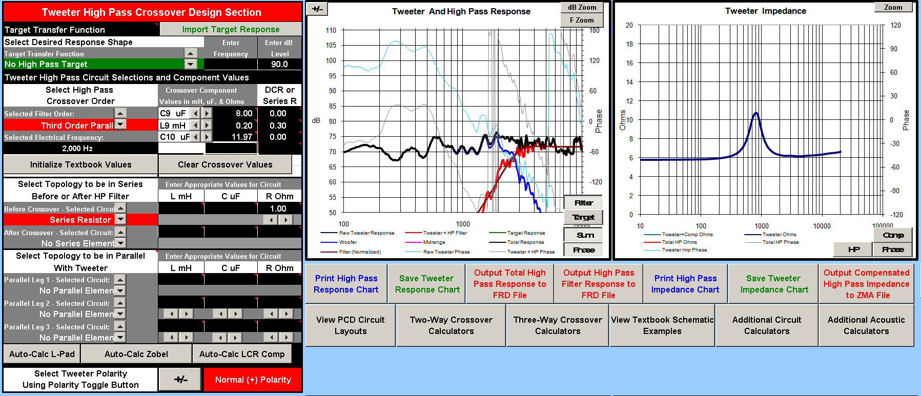
I tried out a preliminary XO and am getting third order for tweeter and fourth order for woofer. Need a quick reivew on the XO and if possible any optimizations of suggestion for improving. The XO file is attached in this link, please feel free to play with it:
https://drive.google.com/open?id=0B2bbY-YB6ikpWk13VVhxc1FEQVE
The XO point is 2k, the tweeter distortion measurement is here: https://diy.midwestaudio.club/uploads/editor/h8/lf5zgonqd6q7.png
Some discussion about the tweeter can be found in this link: https://diy.midwestaudio.club/discussion/341/broad-depression-in-tweeter-response-7-8khz
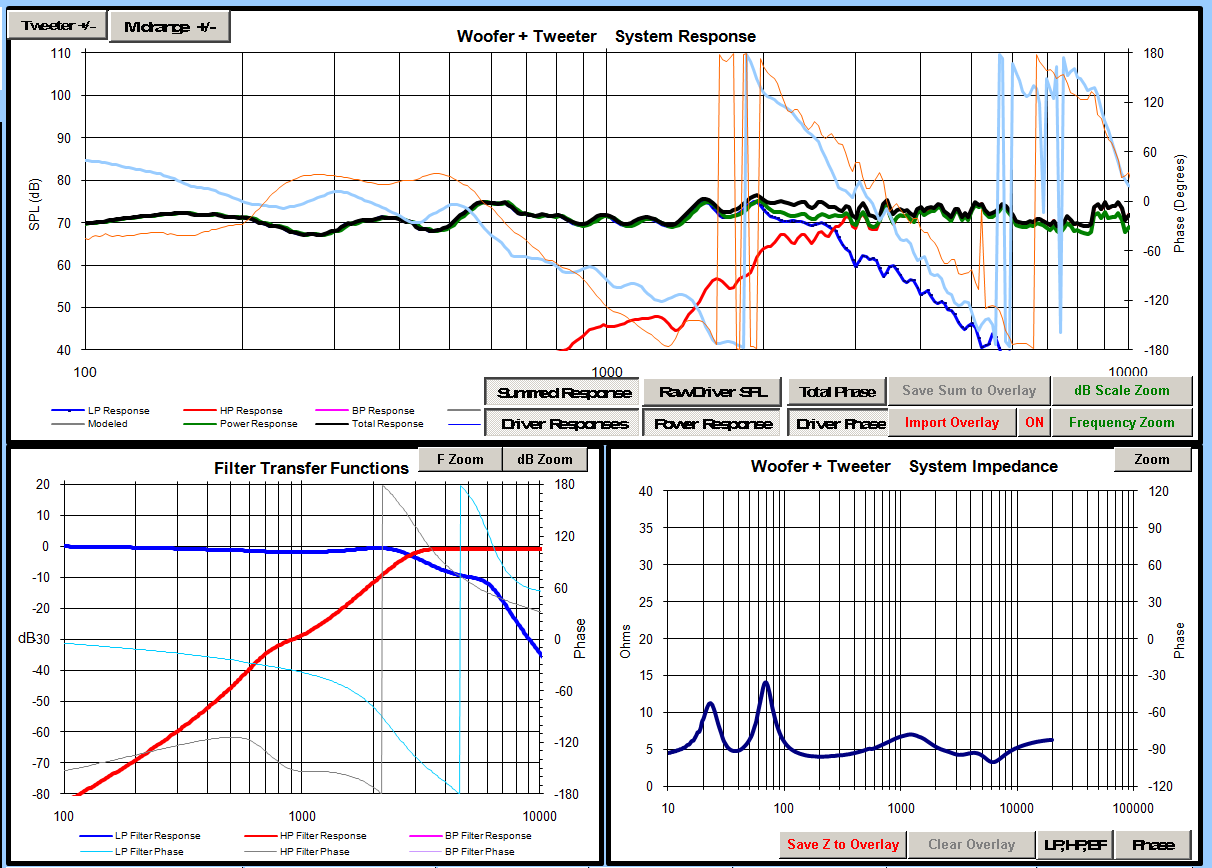
XO Screenshots:


Comments
V5:
When you say forward, does it mean the high are still playing higher and should be taken down a bit? I have a bit more downward tilt right to left on the charts?
V6 XO, more aggressive BSC, and the tweeter response is also tilted down. Now the issue is if I have all those tiny inductors on hand....
Hell, I just like 2nd order.
Are you asking for second order on woofer or tweeter or both?
Expect to do a little experimenting with that capacitor paralleled around the main woofer coil. You will likely find that a high parts count is not necessary for the woofer circuit.
To get the woofer to 3K I like a small inductor for the knee then a larger inductor notch for the BSC. I'd also do the tank on the break up, although this is not really possible to show in PCD.
The filter would look something like this, sorry I can't do legible sketches...
I also noticed the PCD measurement distance was set at 2 meters?
It can be an indicator of a LR alignment with the reverse null. Someone please correct me if my thinking is not on par.
But I do think the mic distance is wrong, it is not 2 meters, i will measure the distance and correct it and try out JR's and your suggestion on the XO.
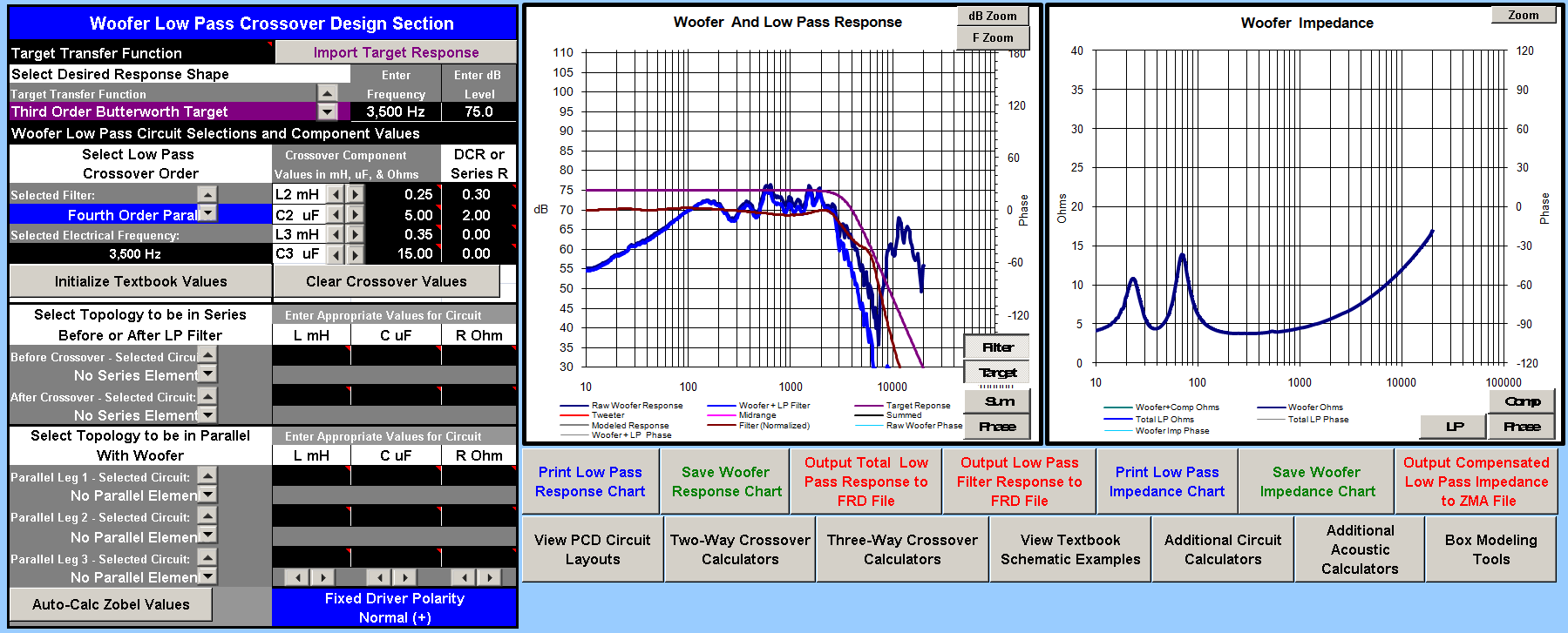
this is my second order o nthe woofer, breakup still stere, about 25db down, would have liked it further squished down, but will try adding a small cap across the L2 inductor and measure and change and measure and see if it makes a difference on the woofer response.
John, I am not able to follow your instructions in PCD. Could you kindly elaborate what i can simulate in PCD and which component I need to experiment with?
V8:
I'm sure it's a typo but you are extracting minimum phase from the FRD files. The minimum phase files and your x and y offsets and your measurement distance are entered in PCD to find your z offset.
Woofer XO:
Tweeter XO:
Measurement:
I looked for a driver measurement and found this: https://www.hifisound.de/Do-it-yourself-Products/Speaker-Drivers/Low-Midrange/Gradient-Select-W-130-AL-8-Shielded-Aluminium.html It seems to have a downward slope already, hence the need for less baffle-step in the crossover.