Site Links
Howdy, Stranger!
It looks like you're new here. If you want to get involved, click one of these buttons!
Quick Links
Categories
Who's Online (0)
D75 chamber sizing

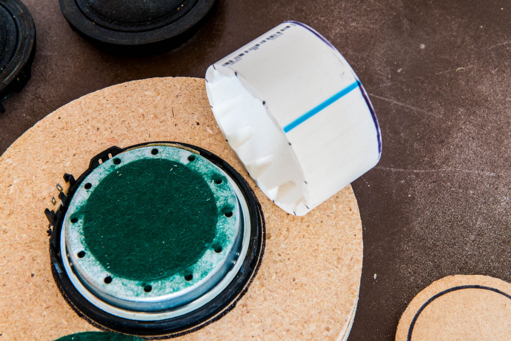
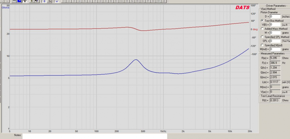
I made a small 3" diameter x 1.75" long PVC chamber for my new (but slightly used) D75MX-21 midranges (thanks again, Dan!). Below are a few construction pics with comments. Qtc with this test chamber came out to 1.2 (see DATS V2 screenshot). Is this an acceptable Qtc for a midrange of this size? Should I make the chamber bigger or smaller?
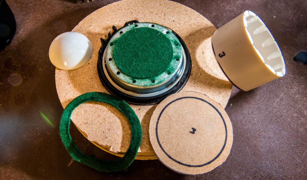
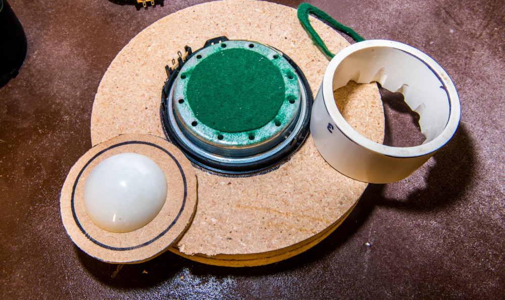
When I removed the green felt along the perimeter to glue the PVC in place, I discovered a large number of vent holes.

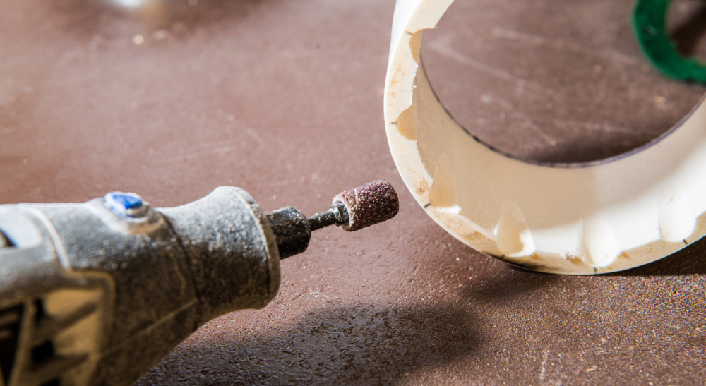
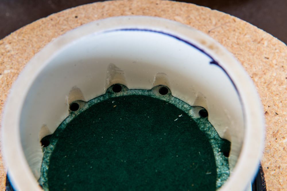
The PVC tube blocked off these vent holes, so I ground clearance chamfers using my dremel tool.
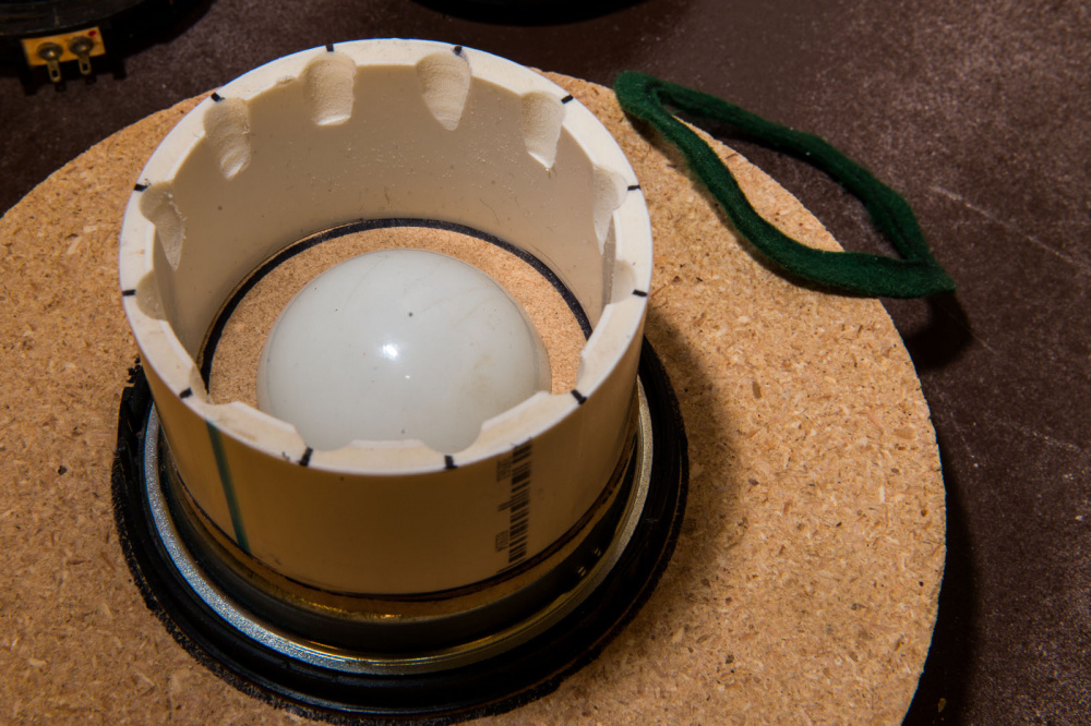
I made a cap out of 1/4" masonite and then glued a white rubber bumper to the center of it to spread out internal resonances.
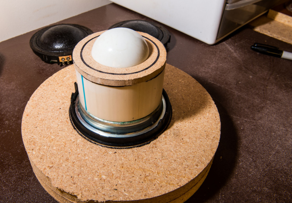
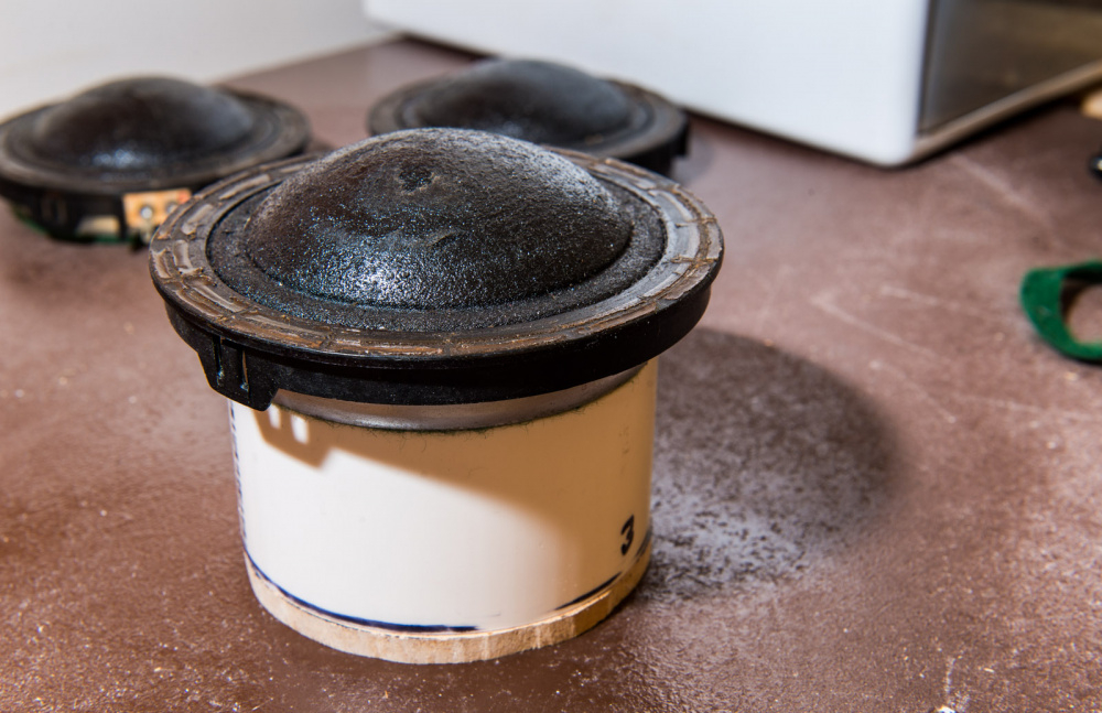
Finished chamber:
DATS V2 measured Qtc with test chamber sealed in place with caulking cord:
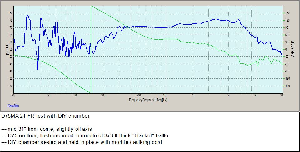
FR measurement at 31", midrange placed on floor flush with thick blanket:


Comments
InDIYana Event Website
Thanks. The DynAudio D76AF spec sheet shows a Qts of 0.9, so I think I need to go a bit larger. I'll slice off a 3.5" length of PVC, re-measure, and report back. I'll also run a few HD measurements.
InDIYana Event Website
You are correct. This is 3" ID PVC (sch 40) and the 3" coupler used to join two 3" pipes together is almost the perfect fit to the magnet. I bought one coupler, which, when cut in half, will work for 2 of the mids. Thanks.
As another test, I doubled the enclosure size from 3" ID x 1.75"L to 3" ID x 3.5"L by stacking two enclosures end to end (have not used the coupler yet). Qtc dropped from 1.204 to 1.029. Fc dropped from 386.9 to 319Hz. I ran an HD test with the 1kHz SPL level set at 95dB. Microphone tip was 32 inches from the dome. The attached HD graph is hard to interpret, so I pulled the following HD data using the mouse. Graphs are also attached:
Freq Percent
100Hz 10.75%
200 5.52%
300 2.19%
400 2.43%
500 2.29%
600 0.79%
700 0.52%
800 0.64%
900 0.52%
1000 0.64%
1500 0.62%
2000 0.44%
2500 0.35%
3000 0.57%
3500 0.43%
4000 0.47%
5000 0.28%
6000 0.18%
7000 0.21%
8000 0.15%
9000 0.13%
10000 0.03%
I have been using some light polyfill material so far. Will test Ultratouch as well.
InDIYana Event Website
I agree. I'm thinking a TMW or TMWW with a SB19 on top crossed with an initial target of 3k or so. Then I will use one or two 5.25" woofers crossed with an initial target of 800Hz or so. Maybe a single ND140 in a 0.75cu.ft cabinet, tuned to 40Hz or so. Baffle would be about 17H x 6.5W. Depth about 14". Power handling would be limited, but I want to keep the baffle width to 6.5" and I have been unable to find two reasonably priced 5.25" 8 ohm woofers that would work well in a 0.75 cu ft box.
I made a flange out of two layers of 1/8" thick tempered hardboard (HDF). I used the type that is smooth on both sides. Both layers are 5.25 x 5.25". The top layer has a 3.625" hole cut to match the dome. I partially rounded over the internal edge with a 1/4" round over bit. The bottom layer has a 4.5" hole to clear the magnet and terminals.
When glued together, this flange will be very strong. I think I will drill 8 mounting holes instead of 4 to prevent flange distortion as I tighten the screws. When finished in flat black with a satin top coat, it should look like a brand new driver!
I glued the 1/8 + 1/8" flange sandwich together with Titebond II. Then, to prevent warping, I inserted all the finished flanges into a makeshift "press" for drying. Also, after several stages of glue "squeeze out" and clean-up, I placed a single layer of paper towel between each flange in the press to act as a moisture wick. All flange surfaces were completely dry when I inserted these towels, so they should not stick and create a mess later on. I'll probably leave the flanges in this "press" for a least a week before taking them out for painting.
I made a total of 4 flanges. This gives me one extra in case one gets messed up.
I finally got around to selecting a chamber size and ran up a new set of measurements (which look very good). I used a 3" PVC end cap, silicone glued onto the back. My local Menards had two types, flat bottom and rounded. I selected the rounded type, which should help to spread out internal reflections a little. It was a very snug fit at first, so I turned or shaved out about 1/32" x 1/2" on the internal opening to get it to slide onto the magnet well. Thanks, Kornbread, for the suggestion. No need to radically dremel out clearance holes this time.
I decided on a target QTc of .78 or so, near maximally flat. Fs came out in the 350 to 390Hz range, which should be perfect for an 800Hz crossover. I stuffed each end cap with 8.5 grams (not ounces) of Acousta-stuf, which hit the target perfectly. I did not use ultratouch, as my tests with this material dropped the Qtc lower than I wanted (in the .5 to .6 range) which rolled off the bass too much.
I finished the flanges with 2 coats of Sealcoat and then 3 coats of semi-gloss enamel. The Sealcoat dried fast, but I had to wait at least a week between each coat of enamel, lightly sanding with 220 between each coat. I glued the flanges on with 100% silicone black gasket maker, careful not to get any squeeze out on the dome suspensions. I pealed and transferred the driver label to the outside before sealing the chamber in place. They now look like 3 "brand new" midrange drivers, ready for a new project!!! I'm thinking high end: Vifa D75's in the middle with JR's Esoteric tweeters on top and the Rival 176 door prize woofers on the bottom.
I was extremely careful when removing the labels. Took me several hours to do this. I wanted to preserve them for future generations of speaker building aficionados. After all, we would not want anyone to confuse these drivers with ScanSpeak or DynAudio D76's. Sure wish I could find a spec sheet for this driver. All of my internet searches have come up empty.
InDIYana Event Website
A, B, and C marked units are very similar'
The dip at 650Hz is due to baffle size:
I added three 20x30 foam core sheets to the baffle temporarily to smooth out the 650Hz dip: