Site Links
Howdy, Stranger!
It looks like you're new here. If you want to get involved, click one of these buttons!
Quick Links
Categories
Who's Online (0)
B&K 277 multimeter restoration

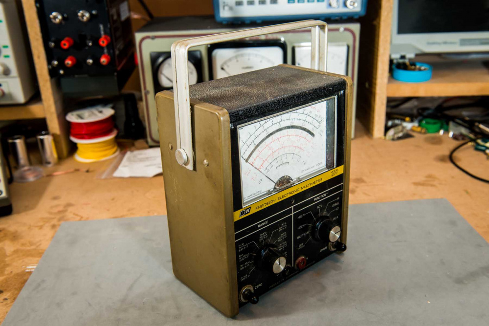
I picked up this vintage (1972) B&K Precision 277 Multimeter at a local ham swapfest. The seller was cleaning out the inventory of a deceased relative.
Stock unit before disassembly:
You might ask, Why waste time on an outdated analog meter that only has a 2-3% accuracy spec? Answer: The big analog movement is good for AM/FM IF peaking alignments. It is also good for testing to see if a pot tracks smoothly. You can still buy new analog meters, but if you want a really nice one the price is quite high (Simpson 260, etc.). So, this is simply my way to get that big, well damped, analog meter movement at a very low cost.
Bill
Comments
Removal of the back panel revealed a severely contaminated battery compartment with one 1.5V D cell and one obsolete type 9V round cell:
At first I thought this was stock, but later discovered that, for some unknown reason, the previous user had replaced the standard 9V rectangular battery with a larger 9V round type. He then soldered two short extension wires onto the standard 9V battery clip to make this work. This, and all the leakage, created a real mess for me to clean up.
Size comparison of 9V round verses 9V rectangular batteries:
Also, over the years, battery acid had slowly dripped/leaked down onto the bottom of the metal cabinet, causing a massive rust build up along the bottom edge. I had to initially use a wire brush on my dremmel tool to grind this down to bare metal. Then I sanded the area with 120 grit and polished it down with steel wool. It took me over an hour to clean this all up.
Masked off for painting:
After 2 coats of Rustoleum high performance enamel (silver rattle can), not the slow drying stuff.
There is an input probe overload protection fuse located on the back of the main PCB. It uses two copper type clip holders hard soldered to the board. The schematic specifies a 3/4 amp fuse, but someone had inserted a 6 amp! This 6 amp fuse was 1.25" long and stuck off the ends of the holders by about 1/4" or so. The fuse was forcefully jammed into what appears to be a 25mm long set of retainer clips. The clips are firmly soldered into pre-drilled alignment holes in the circuit board, so they cannot be moved closer or further apart.
So, I cleaned and buffed the fuse clip contacts with my dremmel and replaced the fuse with a 5 x 20mm type. But the 20mm fuse now looks a little too short for the holder, so perhaps they had 25mm or 1" long fuses back in the day. I'm not sure. Any ideas?
I'd be tempted to solder and relocate the holder if you have room somewhere, like on the area with the batteries. Clearly, it was meant for a fuse no longer accessible.
InDIYana Event Website
There is plenty of room elsewhere, so I will definitely do this later if necessary. So far, the fuse, even though it is too short, appears to have snapped securely into place and does not slip easily from side to side. Contact resistance is very low, because I re-shaped the fuse holder with my needle nose plyers and a small wooden wedge to achieve a better fit to the shape of the smaller fuse.
After removing the front panel knobs and pots, the meter/PCB assembly flips back and away:
I then desoldered the two front panel banana jacks, so that I could remove the meter/PCB board assembly completely:
I then removed the meter by removing the two bolts and sliding it out. The PCB shows 4 large bolt holes, but only the upper two holes are used:
I cleaned and tested all selector switches and pots, then tested all resistors, caps, diodes, and transistors. Everything checks out OK for the parts that can be tested in circuit. No problems found. However, I will be replacing the 220uF electrolytic and the two small 0.47 and 0.22uF tantulum caps, even though they check fine. For the tantalums, I'll be using Wima MKS2 series polyester 63V units, which are very small and will drop right into place. While I am at it, I'll probably also replace the front panel banana jacks with new Pomona 1581-0 and 1581-2 jacks.
220uF electrolytic:
0.47 and 0.22uF tantulum caps (yellow with purple band):
Here is a shot of the PCB top side, showing most parts and the two big function and range selector switches. As you can see, the board uses tons of ceramic, polyester, and mica capacitors. I could only test a handful of these in circuit. Most of them are very low value types, paralleled with lower resistance parts, and thus cannot be measured in circuit. I could de-solder one leg and measure, but decided against this because it is very easy to damage old circuit board traces and these types of caps generally do not go bad. For the switches, it was easy to clean the contacts once I had the board pulled out. I cleaned the circular contacts with rubbing alcohol and Q-tips. Then I applied a light layer of Deoxit fader lube to each circular contact with another clean Q-tip. I did not use Deoxit D5 on any of the contacts or pots.
Tantalum caps last a long time. From Google, " solid tantalum capacitors have no known wear-out mechanism or shelf-life limitations. "
Ron
That's a cool old meter. Glad you're giving it a make-over and will put it to use!
Thanks, Tom. Bringing old equipment back to life is very therapeutic.")
Truly cool stuff Bill, I need to find a hamfest swap meet near me!
http://www.arrl.org/hamfests-and-conventions-calendar
What I like to do is click on the arrl.org hamfest calendar linked above and then do a search for events in my area. There are usually 3 or 4 local swapfests per year, some small, some fairly large. The nice thing about these events is that you can avoid the overpriced fleabay type experience because there always seems to be several sellers there that are simply cleaning out a garage for a friend and know nothing about what they are selling. They are just getting rid of it to clean out the garage.
Thanks Bill, I just looked and there is one next weekend about 45 minutes away.
I did some testing of the meter alone, out of circuit. Using the DATS V2 resistance button, I get a measurement of 3.3k ohms across the two input terminal bolts. With the capacitance button, I get 0.0024uF. With the inductor button, I get < .05mH and 3.3k ohms DCR with a pop up message stating that "This does not appear to be an inductor". The schematic and manual show the meter to have a current rating of 50ua (microamps) but no other information is provided.
So, this is a very sensitive, low current, low voltage meter designed to be driven by small signal transistors. There must be additional parts (diodes, capacitors, etc) inside the meter, but I would have to remove the 4 bolts on the rear of the meter and then very carefully pry it apart to see what's inside. Since doing this could easily damage the meter movement, I decided to leave it alone and proceed on the assumption that the meter is OK and hope for the best.
I would guess that you are just reading the coil in the meter movement.
I was poking around to see what transistors these use and came across a thread on Antiqueradios.com that might be of interest, if you haven't already seen it -
https://www.antiqueradios.com/forums/viewtopic.php?f=8&t=232627
Thanks, Nick & Tom. Good info. I was not aware of this thread. Looks like I have a potentially excellent meter on my hands. The transistors in my unit all test OK without power applied. With battery power applied, I can also easily set the bias pot to the 4.7 volts specified in the manual, which is a very good sign.
There are three silicone NPN transistors (T0-92) and then one dual N channel FET in a single T0-39 package with 6 leads coming out of the can. The B&K manual only shows the B&K part number for these transistors, so cross referencing them to a currently available part would be difficult. I also picked up a B&K 501A semiconductor curve tracer from the same guy, so if I can get it working, I may be able to pull and measure unknown transistors like this myself. The 501A can measure both bi-polar and FET types of the small signal or high power variety.
This help find what you need? https://ebay.com/itm/184449768033
I don't think so. A curve tracer should be able to give me better information about a transistor because it can output a complete set of curves to my scope.
Below is a link to a video by xraytonyb comparing these type of small, handheld testers to his DIY curve tracer. In the end, I should be able to get my B&K curve tracer working for about the same cost as one of these cheaper $20 handheld type units. Or so I hope. It's always a gamble when attempting to restore an old piece of test equipment.
I don't quite understand the whole matched pair in a single package idea. I understand the need to thermally couple them together, but I would think it would be quicker & easier to match individual transistors instead of fabbing a whole new part just because of the package. I guess it might be cheaper in the end and humans stuffing the boards couldn't get the pairs mixed up if it's a single device.
Probably a marketing dept thing to boost sales. In the early 70's, the new solid state vom's could turn on fast and start measuring in seconds compared to the older vacuum tube volt meters. By putting the two transistors in a single package, they could probably get the meter to boot up and stabilize faster. Just a guess.
WooHoo! Project successful. After biasing and calibration, I bolted it all back together and guess what: It actually works. I ran it through a series of high and low AC, DC, and resistance measurements and everything is spot on. It can even measure resistances accurately up to as high as 100 megaohms. My digital meters can't do that. Turns out, the only real problem with this meter was the dead 9 volt battery and the contamninated battery compartment.
Before buttoning it up, I installed a small piece of particle board along the top edge to hold the meter in place. This replaces a missing bracket that originally held the meter in place along the top edge. Initially, the meter was loose and moved in and out along the top. Now it is rock solid.
The finished meter:
Gotta love old gear.
Excellent! Another useful addition to your bench.