Site Links
Howdy, Stranger!
It looks like you're new here. If you want to get involved, click one of these buttons!
Quick Links
Categories
In this Discussion
Who's Online (0)
Ported vs. MLTL box for Ciare HW251N Woofer

Hey Everyone,
I was asked to make a DIY 3-way design with some of the Ciare drivers that PE just started carrying, and I'd like to get your thoughts on the bass arrangement. I'm trying to decide between a conventional bass reflex cabinet and a MLTL. I realize MLTL is (in essence) a bass reflex cabinet... just with extra attention paid to the arrangement of the volume inside the cabinet. Life is busy enough that I only have a mish-mash of thoughts on the subject and not a clear cabinet arrangement for a potential MLTL at the moment. Just some hornresp modeling that looks like a decent rough draft. Thought I might ask the crew what benefits/drawbacks you see. I have never designed my own MLTL before, which is kind of the allure for me. I have messed with HornResp enough to have a crude idea of what I'm doing... but I still suck at it! Please have a look below and share your opinion. Is this driver a good fit for an MLTL arrangement, and do you think it's worth the trouble?
Anyway... here's the drivers I will be using. All Ciare
Woofer: 10" HW251N (8 ohm)
Mid: 5" HWG130-4 (4 ohm)
Tweeter: CT440 Horn Tweeter (4 ohm)
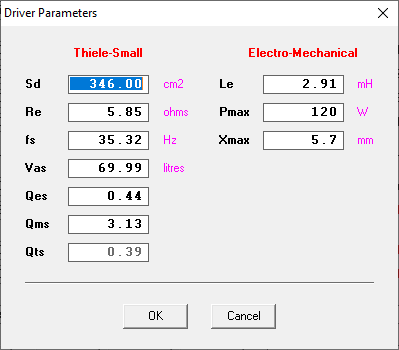
Average T/S parameters of the two woofers I have after 12+ hours of high excursion break-in with 20Hz sine tone
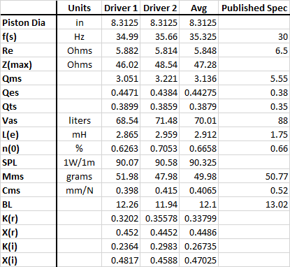
BassBoxPro suggests a vented arrangement of Vb=2.25cuft, Fb = 44Hz, F3 = 39Hz with a 4" diameter x 4.287" single flared vent. I honestly tried to use two smaller vents but the lengths of the vents were very short, or the air velocity would exceed 17 m/s with minimal power applied.
HornResp... oof. I used the Loudspeaker Wizard function to come up with this response. My rough draft has ad a 186cm long line length with an 8"x7" duct area (~360 cm^2). Vent is 100cm^2 by 10cm long. Current HornResp models can't offset the port from the end of the line, so I can't include that in my model. Seems like I could get an F3 around 40Hz as well... but I am probably doing a poor job of damping out resonances from the 200 Hz+ range where I would be crossing to the mid in it's own sealed cabinet. Someone please rip the attached models apart and show me where I can improve!
HornResp record is attached as .txt.
Thanks!
Keith
Comments
The standard ported will have better power handling. Bump the tuning up a few more hertz, and I think it would be downright marketable.
If this were to end up in the Fall sales flyer, that's the option I'd choose.
Thanks @Dirk, putting my marketing cap on for a minute, a standard ported cabinet is absolutely more approachable for most DIY. I'll model a bit more with different port tunings and report back. Is your suggestion for higher tuning just to get a little more bump/fun out of it? My initial choice here came from some forum comments Jeff Bagby made about his preference in box behavior based on roll off point. I saved the post in a word document... The text being as follows:
"One of the things I have learned over the years concerns the relationship between the room, the speaker’s F3, bass tuning, and our perception of the bass response. I have found that when speaker roll-off in the 100 – 70Hz range a small hump of 2-3db just above the roll-off frequency can make the speaker sound more balanced and even more extend. This is the same thing Harwood did at the BBC in designing the LS3/5a. But if a speaker extends into the 50Hz range then a little hump works best, one of only 1-2dB. If a speaker extends to 40 Hz or so then it sounds the most balanced if it is as flat as possible. And finally, if a speaker extends below 30hz, and especially if it reaches 20Hz, then an over damped response with a gentle drooping at the bottom end sounds the most balanced in most rooms due to room pressurization gain."
So... I figured I stand a good chance of success if I follow in Jeff's footsteps!
I'm not about to contradict Jeff! My logic was that the sort of person to decide to build a big woofer 3-way may benefit from the extra bit of power handling that comes along with the higher tuning--and yeah, perhaps a bit more excitement. We're talking about a 1dB hump on the lowest of the low end, so it's probably splitting hairs.
Hah... Yeah. I thought about how you might respond to that as I put that last response together. We all love and miss Jeff, and I didn't put that out there to put you in a difficult spot of defending a position against his logic")
I like a little more boom in the room myself, so it's probably a fun experiment! All my builds tend to get finished with a permanent PVC port tube before I actually check port tuning. Maybe now is the time to finalize port tuning and installation at the end!
It all comes down to personal taste. That was Jeff's taste, build it to suit your personal preference. There's no right or wrong, if it's what you like.
I don't have time today to run your HR model - but in brief, my MLTL process is to find my optimum BR model in Unibox or WinISD, then use that volume and port parameters in Hornresp. Briefly, the MLTL with an offset driver is probably what you want.
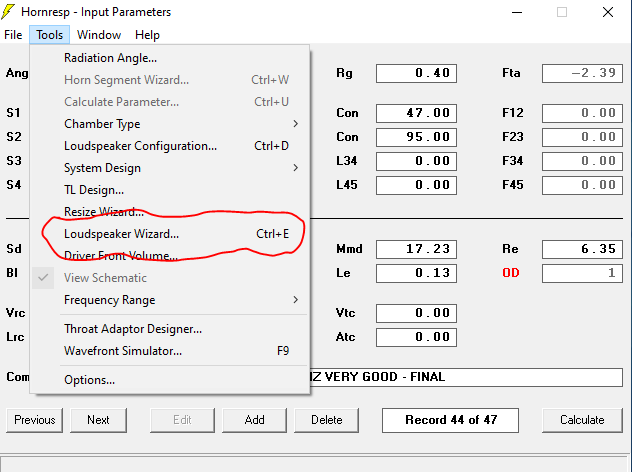
The driver center will be at the line between S1 and S2. Once you generate the model, hit "calculate", then go back to the input parameter screen and now you can (by magic) get to the "Loudspeaker Wizard"
Go into "power" on the lower left, and "segments " in the low middle.
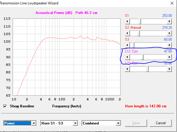
Then play with L12, which is the offset of you woofer from the start of the TL
Start with about a 1/3 offset, then move it a little up and down. You should able to find a length where the first harmonic is pretty well neutralized.
A TL is not inherently more difficult to build than a BR, but they tend to be towers due to the line length.
The newer versions of HR do allow you to offset the port, but that is a minor adjustment IMHO.
Having said that, IDK about a MLTL 3 way. The mid chamber might interfere with the line. Shucks.
@rjj45 thank you sir! I have a different MLTL design that Paul K helped me with where he was a big fan of offset ports. That design was next in my build queue before these drivers showed up on my porch! I'll look again at the help file for hornresp to see about the offset port. I did not see that in my last check through. Highly likely it's just called something isn't obvious to me.
There are lots of tips for Hornresp, one is to design the volume and tuning for a 2-3 Fb hump at F3, then when you add stuffing it flattens out
Speaking of stuffing, suggest always using 100% stuffing in S1 with about 500 to start
I’ll be able to play more with your model next week.
First look shows 75 cm offset L12 is best
I will be using that woofer in my Veritas (10"2way) design. This is a stand mount MLTL cabinet.
Keith
I'd second Dirk.. I'd go with vented box tuned a bit higher. If it's a 2 way then MLTL it is.
I really don't have experience with TLs yet, but personally, a small midrange chamber wouldn't stop ME from trying it.
I bought some solidly built bare mdf TQWP towers from a guy who specifically built them for the same fullrange drivers I have (using the mh-audio.nl calculator). Though, he had a tweeter hole cut and was messing with a bunch of PRs on the back. I honestly was thinking of just gluing more MDF to the front and back to cover all the extra holes and leave the cutouts still open on the inside. Then just install the appropriate length port for mass loading. I had my doubts the cutouts would make that much of a difference to the performance. But maybe someone will tell me otherwise?
Hi All, if I do choose MLTL, I'm not worried about having a mid chamber bump into the line a little. I had similar concerns on the yet-to-be-built design that Paul K helped me put together. Without digging up all the emails for his exact words, the gist was that the performance of the line wouldn't be degraded significantly as long as I didn't bump out too far into the line. @VCORPUZ23 - You say MLTL if it's a two-way... is that just because of the mid chamber comments? @DrewsBrews - regarding the extra holes and cutouts in your cabinet, I suppose if the holes are big enough they would start contributing to the volume of the line, but I'm not sure you'd be able to model it well enough to predict it. If you're really considering it, maybe you can cut some plugs and fill the holes to negate it?
The PRs were actually glued into routered recesses and removing them tears out a bit of the MDF. Due to that, trying to make and fit exact size plugs sounded like no fun at all... But you describe it as more of a volume change issue.. So maybe I don't need to be so exact, and could just attach some slightly smaller mdf slugs to the inside of the new "baffles" to at least put back the majority of the missing material. That sounds more manageable. Cool")
TRUTH! I have to be hellbent on saving a cabinet to go that far.
Keith, I ran up a TL model, using your average T/S parameters, using the Leonard Audio Transmission Line program. I don't think this program is available anymore, but I still have a copy of it running on my Windows 7 laptop. I used Bob Brines stuffing density "fudge factor" of 2.5X, which, as I recall, gives results similar to the MLK mathcad worksheets (correct me if I am wrong, I can't find the old thread where they discussed this at length). The enclosure is 45" tall (internally) with the woofer located 18.5" down from the top. This gives you plenty of room for the tweeter and midrange placement above the woofer. The enclosure cross section is 9 x 10" internally from top to bottom (no taper). The port is 4" ID by 6" long and is located 7.14" above the bottom of the cabinet
Here is the SPL screen showing terminus, driver, and system output. F3/6/10 39/33/29
Rear Element 0: This is the first 22.5" section of the TL, stuffed at a rate of 0.5 lbs/ft3 (using the 2.5X stuffing fudge factor)
Rear Element 1: This is the 2nd TL section, 15.35" long, lightly stuffed (lined with 1" denim or foam):
Rear Element 2: This is the 3rd TL section, 7.14" long, lightly stuffed (lined with 1" denim or foam). It is necessary to break this section out in the model so that I can place the port at a 90 degree angle between the two sections.
Rear Element 2.0 (port). The port is 4" ID by 6" long, located 7.14" from the bottom of the cabinet. It is modeled as "open" with no stuffing.
And finally, here is the driver T/S parameter screen, showing the data I used:
Hope this information is useful. I have designed a couple ML-TL's using this program and they seem to have turned out OK. But it is somewhat hard to tell because when you get done it is very difficult to accurately measure the low frequency response, in room, to confirm the model.
Keith,
Yes.
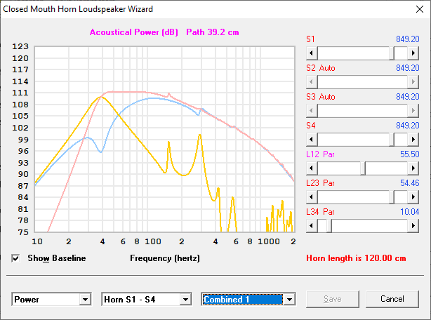
Look at all those port resonances.
Thanks @4thtry , I appreciate all the effort you went through! I find it interesting how many programs have come and gone in one fashion or another with regard to transmission line design. The size of this line is quite large as I expected for a mid 30hz Fs driver. As far as confirming the model... would Jeff's quasi-anechoic measurement methods work here, same as any other speaker? In my head we just measure the driver nearfield, and measure the port output nearfield, then sum them properly. Am I missing something?
@PWRRYD , Yes... I kind of expect to deal with port resonances by rolling the woofer off to the mid around 250-300Hz as a ballpark guess. No modeling done to back that idea up yet. Think I'd still have issues in that scenario?
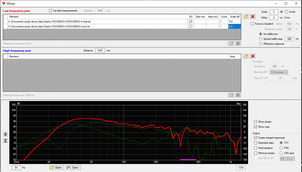
That should work, in theory. What I was referencing was the problems that I have had getting the OmniMic software to sum NF cone + port. Sometimes it works. Sometimes it produces really goofy looking summations. Has something to do with the way OmniMic measures phase. I think @dcibel highlighted this problem a while back. But now that I have my two channel measurement system set up and working, I should be able to get more accurate summations in VituixCAD. As long as I click the NF button when converting the impulse response to FRD, the merger tool should sum them properly. But since this is a 10" woofer with 8.31" diameter cone, the NF cone meaurement will only be valid up to about 518Hz (4311/8.31).
Nearfield measurement with timing reference make verifying cabinet model very easy. Just measure nearifeld of driver and measurement right at port exit (mic in line with baffle surface) and merge in VituixCAD merge tool. Select "no baffle loss" for comparison against cabinet model. Enter driver and port area for automatic calculation of amplitude adjustment, but I usually just do this visually, port and driver response should converge approaching 0Hz. This works well, keeping in mind that into the midrange the driver output will contaminate the port response some, since port output will be very low, but driver output will remain.
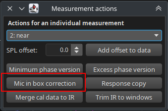
Other method if you don't care so much about separate port and driver response it to simply stick your mic in the box. Take measurement and then process with REW "mic in box" button, found under ALL SPL -> measurement actions. You can do the same in VituixCAD calculator too, you will see a button there for "mic in box". This works very well at low frequencies, up to the point where cabinet reflections start to take over, usually 200-300Hz, higher for small cabinets.
REW:
VituixCAD:

Ya, the 150Hz peak would be 1/2 wavelength at 45" (the internal cab height), the 300Hz peak would be 1/2 wavelength at 22.5", and the 750Hz peak would be 1/2 wavelength at 9" (the cross sectional distance). Every ported cabinet that I have ever measured suffers from some type of peaking in the 400-800Hz area. Only the tall ones have 100-300Hz peaking. Moving the woofer down the line 18.5 inches gave me the lowest 150 & 300Hz peaks. I can reduce these peaks further by increasing the stuffing density, but too much stuffing kills off the models low frequency extension.
Well... my brain hurts trying to figure out this MLTL stuff by messing around in HornResp. Better to work on this tomorrow after some sleep. Thanks all for the comments!
It takes a while to be comfortable with "messing around" in Hornresp, but even when you do get comfortable (like I am now), it will still take many hours trying various configurations until the final design is really optimized. I will work on your Ciare some more in the next few days. One thing I did notice is that your T/S params in Hornresp for the Ciare were a bit different than the P-E data. Were those your measured params after breakin?
Yessir - those average parameters are my measured parameters for two drivers after break-in. I am always paranoid when my TS parameters don't match the manufacturer, but I have little choice except to roll with it.
OK. We're trying the HornResp bit again. I tried to model @4thtry 's Leonard Audio model in HornResp but I didn't get near the same answer. I ended up with a significantly larger Xsec area for my line, at close to the same length. Please critique and share your thoughts!
My questions and takeaways are:
1) Anyone got a good reference for acoustic impedance in mks rayl units? I need to google more. I chose 500 based on @rjj45 suggestion above. I still have no idea what I'm really calling for here.
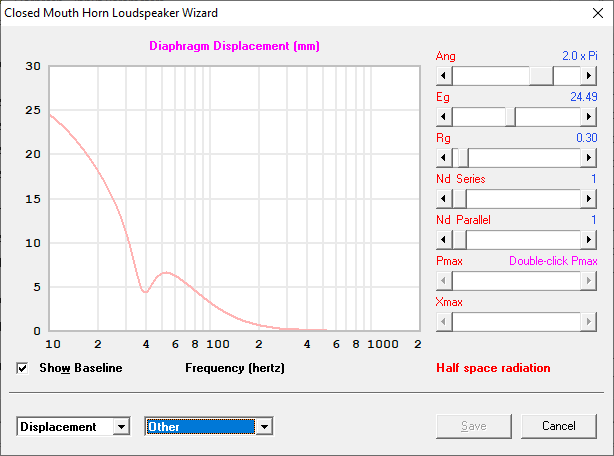
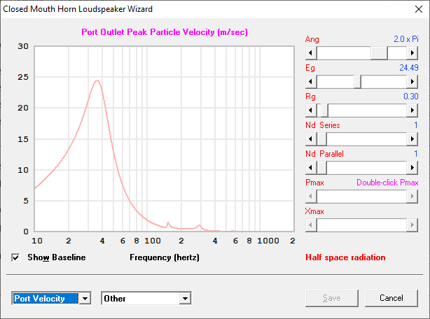
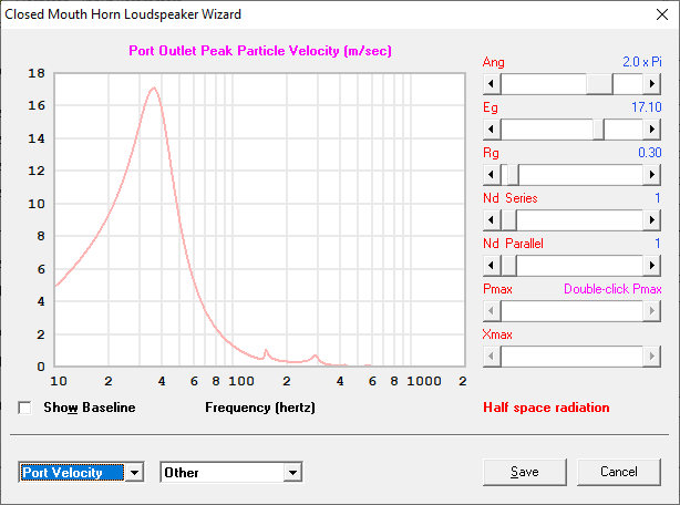
2) I likely need to increase my port xsec area and length to reduce my airflow. I am hitting 17 m/s port velocities at 35hz before I hit xmax, let alone xmax+15%
3) This would be a big honkin box. Good looking performance from a standard vented cabinet was happening around 67L in volume. This MLTL took 102L. +1 for standard ported!
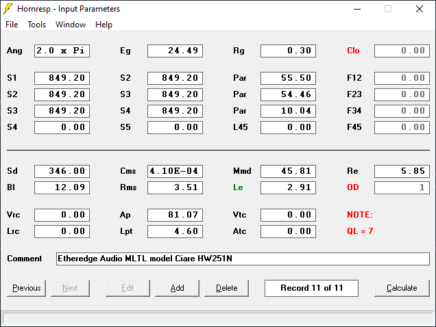
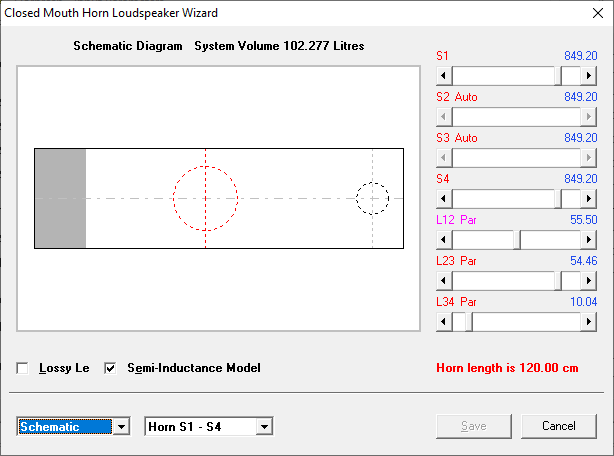
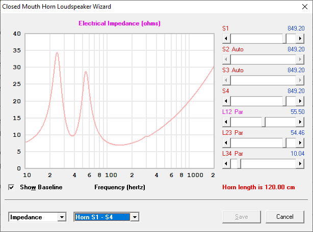
Overall Design Modeled Below:
Line Length: 47.25 in / 120.015 cm
Line Width: 13 in / 33.02 cm
Line Depth: 10.125 in / 25.7 cm
Line Xsec Area: 131.625 in^2 / 849.2 cm^2
Line Volume: 101.92 L
Port Diameter: 4 in / 10.16 cm
Port Area: 12.57 in^2 / 81.07 cm^2
Port Length: 1.8125 in / 4.6 cm
Port Location from end of line: 4.1825 in / 10.04 cm
Offset Woofer Location: 21.85 in / 55.5 cm
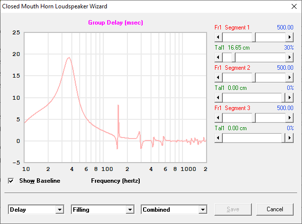
Stuffing Segment 1: 6.56 in / 16.65 cm
Stuffing Acoustic Impedance: 500 mks rayl
QL: 7
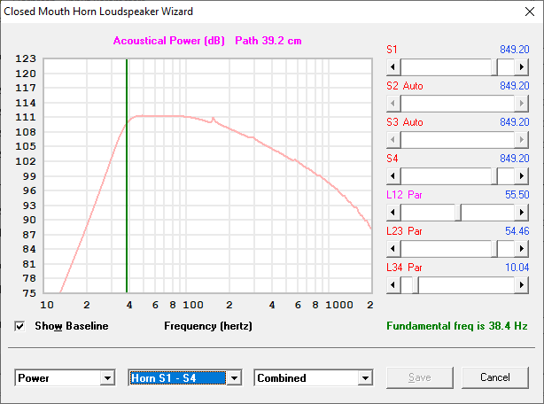
Here's the HornResp Output
Keith - that's looking a bit better, but there should be no reason that the volume needs to be so big. Please post this latest model, and I'll mess with it.
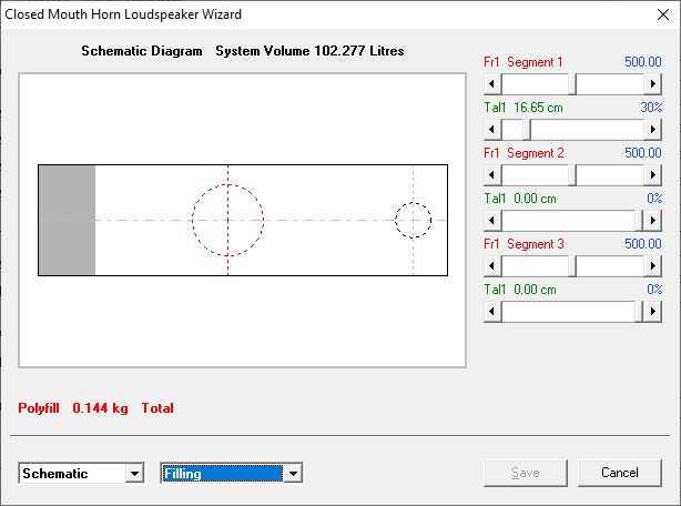
RE: stuffing
One of the screens in "Loudspeaker Wizard" will show you the total weight of the stuffing - I think it's "Schematic" with "Filling" in the second box. I worked with Paul Kittinger on several MLTLs, and he usually had stuffing at 100% in S1 and about 30% in S2, and that is what usually worked best in my Hornresp models.
(Part of) My process is to Zero out all stuffing, then play with L12 until the first harmonic is at a minimum. Once that is optimized, then move S1 stuffing to 99% and start adding stuffing "weight" (or MKS) until the next couple of harmonics squash flat(ter), while making sure that you don't kill your F3 too much. Once you've got that pretty well in hand, you can add about 20-30% of S2 stuffing at the same density as S1. One aspect that I never coordinated is that Paul would typically use something like 10 oz stuffing, and I would come up with about 6 oz or so. But I really trust the Hornresp models, and they measured just like the model.
@rjj45 Thanks sir! Here's the HornResp file for the model I posted above. I'll play with the stuffing some more too. I've spent the morning trying to come up with some kind of stuffing rayl number that makes sense. I like the idea of using bonded dacron sheet to keep the density uniform through the stuffing range, but I have no idea how to really convert a mass based density that I can calculate into an acoustic impedance rayl number!
OK. @rjj45 ... One more model because I have fallen down the rabbit hole. Shaved about 20L out, and followed your stuffing suggestions. Feels pretty good for the moment pending a few questions, and building with some extra volume for mid/tweet chamber.
Question on QL value to use:
I recognize there's some wiggle room in these simulations for me to guess how good I am at making a vented box with minimal leaks. Using QL=7 gives an OK answer. Bass roll off begins around 80hz and slowly rolls 3dB down to 40Hz. Using QL = 15 gives a more exciting answer to me of solid output until 60hz before rolling off 3dB down to 38 / 39 Hz. I noticed Martin King's last paper on TL alignment tables (and subsequently their inclusion in HornResp's TL wizard) uses a QL of 15 as their baseline assumption. I see that as evidence this QL value is acceptable for quality builds like I (like to think) I do. Any thoughts / disagreements with that logic?
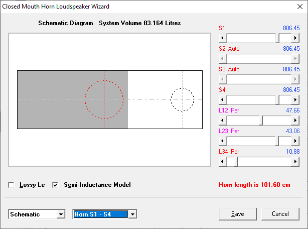
Overall Design Modeled Below:")
Line Length: 40 in / 101.6 cm
Line Width: 12.5 in / 31.75 cm
Line Depth: 10in / 25.4 cm
Line Xsec Area: 125 in^2 / 806.45 cm^2
Line Volume: 83.16L per HR, my maths say 81.9
Port Diameter: 5 in / 12.7 cm
Port Area: 19.63 in^2 / 126.68 cm^2
Port Length: 3.819 in / 9.7 cm
Port Location from end of line: ~4.28 in / 10.88 cm
Offset Woofer Location: ~18.76 in / 47.66 cm
Stuffing Segment 1: 100% (~18.76 in / 47.66 cm)
Stuffing Segment 2: 30% (~5.09 in / 12.92 cm)
Stuffing Acoustic Impedance: 500 mks rayl
QL: 7 or 15
System Model
Output with QL =7
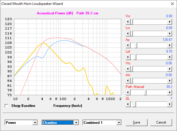
Output with QL=15

Honestly Keith - I think that's probably an optimum TL for that woofer. I kept playing with the basic offset port model for the Ciare, and was coming to the conclusion that it wanted a big box to shine.
You done good!
I don't know offhand about Ql - I know Jeff gave some advice that I saved somewhere.
In the wizard screens you will also find the Kg of polyfill that gives you a decent starting point. I like to provide removable panel to adjust the stuffing. My preference has been to put the stuffing between the driver and the port. You need to be careful the insulation doesn't poop out the port.