Kid could use a new basketball court since you stole the pole that held his last hoop up. Two birds, one stone.
LOL. I like the way you think.
Well, I have a daughter but she doesn't use the basketball goal anyway. I'm the one who does. And since my wife, who played in high school, beats me at H-O-R-S-E I was happy to dismantle that thing.
I measured in the backyard again but this time with pavers. I made a run about 1.5 x 8 feet long of 1.7" thick pavers purchased from Lowe's this morning. Here's a photo of the setup:
Here's the pavers result (blue) overlaid with the driveway measurement conducted a couple days ago (black) and the plywood measurement (red):
I then decided to try a few things...
So, first I laid a strip of plywood ON TOP of the pavers, running the length of the pavers (blue). I didn't take a picture of this but it is literally the same as above just with plywood laying on top of all the pavers.
I also tried laying the plywood crossways in front of the microphone (green).
I think this combination of data is showing me that I need more than just a length of pavers between the mic and the DUT. I need a large area. Something like a driveway or patio where is more concrete area.
Since I was already in my backyard I decided to do a quick sanity check to make sure nothing was wrong with the hardware or software by measuring the speaker on my back patio like you see below. This measurement was gated due to the wall you see in the photo, so it does't have the high resolution of the other measurements.
Conclusion:
From the above you can see the patio sanity check works out; it matches the driveway response fairly well (with less resolution due to the ~ 4ms gating). So, it is confirmed, the pavers/plywood/grass backyard method cannot be used. I (you/we?) need a much larger slab of concrete than a 16 inch wide set of pavers and/or possibly multiple layers and much more area of plywood.
I honestly thought the pavers would make up the difference. But they did not. I don't know if the result is because the pavers are not dense enough to fully reflect sound, if it's the fact that there is grass around, that the pavers are not 100% flat (but lined up well enough I would have thought), or that my backyard has a gradual slope. I'm just lost on the explanation here but maybe it's the culmination of different things. Not only does the top end still experience a large dip around 6kHz but there's also a dip in the midrange compared to the driveway measurement.
And, yes, I realize this may seem like I am obsessing. I am. I simply want to get the most accurate measurement I can but I also want to understand what makes other methods inaccurate.
Ok, now that the decision on where to measure has been made, I want to investigate how to measure:
1) Mirror vs no mirror
2) Mic angled vs mic flat
Note: Any photos I show were taken today in the sunlight to show you how I measured LAST NIGHT. They are just for reference; the measurements were all made at the same time as the datasets above.
All of the following measurements were done at 1 meter to help me get a little bit more reflection-free time but it did not effect the relative trends that I measured at 2 meters. Here is the comparison (note: the mic was flat on the ground as you can see in section #1 below):
Okay, so the mic will be placed at 1 meter for all following test results. Moving on...
#1) Let's look at the first concern, with and without a mirror:
For setup reference, here are the two setups:
And when the mic is flat, there is just a small gap between the mic and the surface:
Here are the results:
As you can see, the comparison with and without mirror laying flat on the ground/mirror are practically the same. So, assuming the surface you are measuring on is a hard surface like concrete I would say you can go without using a mirror.
Now, just for the heck of it, let's see if adding a mirror and angling the mic changed anything...
Pictures of setup. The mic is angled toward the ground and the shell is touching the actual ground.
Results:
Not a real surprise that the difference here is essentially null. We saw in the above when the mic was flat the mirror made no difference. Same thing here with the mic angled.
Now, that means we can assume that the results With Mirror == Without Mirror. Regardless of mic position.
#2) Mic angled vs mic flat:
Comparing "without mirror", referencing the above photos for setup, here is the overlaid results:
These results show higher frequency combing. I can't say how much of this is the result of the mic holder causing reflections or if this is literally all caused by the mic being angled. I would need to remeasure with foam or something that wouldn't cause a reflection to hold the mic at an angle to know for sure. I will need to consider this a bit more. What I've read is that aiming the mic down is best to get it on the same plane but I worry about the reflection from the holder so I will try to come up with a way to do this. Maybe something as simple as a thin block wedge where there is no empty space and therefore no chance for a reflection. If I re-test this aspect I will post back the results.
***** Extra Info! Wind matters, duuuuhhhhhhh.... but I still wanted to see how much. *****
And for those who may wonder about wind, I measured twice yesterday. All the data I showed for the pavers results were done in the morning and then again at night. It was quite windy yesterday morning with gusts up to about 15mph. So I scrapped that and decided to wait until the winds subsided. But I saved those results and have plotted them vs the nighttime measurement below. "Wind" is red. "No wind" is black. Again, these are with pavers and intended only to show the effect the 10-15mph winds had on my mesurements (2 meter distance).
From what I'm seeing in all my tests this is what I feel comfortable with and how I will conduct my tests (barring no friends suddenly revealing they own a basketball court):
Measuring in driveway (or otherwise large, flat concrete area). Mic flat on ground. Speaker titled toward microphone to line up the tweeter axis with the mic. No wind.
Would you be able to do the same test using a wall? If you place the speaker at the base of a wall and angled up towards the ceiling and place your mic above the speaker.
Would you be able to do the same test using a wall? If you place the speaker at the base of a wall and angled up towards the ceiling and place your mic above the speaker.
I think that would alter the baffle step contribution.
Yesterday the weather was nice. No wind. The neighborhood was quiet. So, I set out to measure the S400 and get it done. I ran horizontal and vertical measurements. About 30 total measurements.
But, I made a stupid mistake. Given that it seemed the "mic angled down" measurements were a close match to what was expected, I decided to go this route but I made a foam "shroud" to prevent any reflections from the mic holder altering the result. Like so:
My mistake was: I didn't test the 'shroud' first. So, I completed all of these measurements, went and looked at the results and saw this:
Man, that is a LOVELY sight to see. Look at that high resolution! Oh, but wait.... Above 3kHz the data is junk!!!! Sonuva!!!!..
So, today I measured in the garage (ground plane, 2 meters, gated to about 8ms): 1) with shroud and 2) without shroud. The "with shroud" reduces output above 3kHz by about 1-1.5dB.
I am about to lose my ever-loving mind here.
I really want accurate data out of a single measurement (ie, no 'splicing' or 'blending'). My issue with splicing is it requires nearfield measurements of each woofer/vent and results in a nearfield bump. My issue with blending is it requires additional modeling that would also increase lead time. Plus, there's the concern that you really can't just assume a NF mic measurement of the different sources will behave the same off-axis; especially when you don't have high resolution due to the window size. And then imagine splicing a single NF set of measurements with multiple off-axis measurements. But from this little bookshelf alone I can already tell you the polars wouldn't be correct and the resolution/accuracy in the midrange would also suffer. Proof? Look at my above set of horizontal measurements; see the split begins about 100-200hz? On-axis NF + FF stitching won't show you that. I want that data.
A single ground plane measurement would give me data down to < 30Hz; that's resolution better than some anechoic chambers. It also means no need to blend or splice. That also means there is less chance for error in complicated enclosures where there are different sound sources on different sides of a large enclosure (ie, woofer on front, vent on back). Cons of the ground plane measurement are simply that it is outside and I have to contend with weather and neighborhood kids. Not to mention having to walk 40 feet to go turn the speaker (and I have played with different automated designs but they all elevate the speaker on a platform which only alters the data).
I have one more thing I want to try. If that is no bueno I'm gonna have to really think this over and consider the pros/cons of the above. I keep falling back to the driveway ground plane measurement but again, that has its own set of cons. I think my only solace in all of this is that "if it were easy, everyone would do it". I just didn't realize how much legwork I was going to be putting in to get confidence in my measurements. I almost wish I didn't know what the data should look like. I tell ya', ignorance is bliss, folks.
If any of you think I am being too complicated about this: I am. I know it. But that's because I want this data to be accurate. I could easily do some 5ms windows in my garage, do some NF measurements, slap 'em together and call it a day. And that's not a knock against others who don't have a choice but to do that. It is simply that I know I can do better... but how badly do I want to do better is the real question. Hey, if nothing else, maybe I can help you guys avoid the same mistakes I am making.
Do you think rotating the mic would have the same effect as rotating the speaker. Would save you 40 feet every turn, assuming you are sitting near the mic.
Was the inside garage ground plane was not enough distance compared to the driveway?
Do you think rotating the mic would have the same effect as rotating the speaker. Would save you 40 feet every turn, assuming you are sitting near the mic.
Was the inside garage ground plane was not enough distance compared to the driveway?
Well, you'd have to rotate the mic about the speaker. Turning the mic would just give you a response based on the mic's off-axis response which isn't the same as the response based on the speaker's off-axis response. And moving the mic around the speaker in a radius physically means you're moving further than you would if you just rotated the speaker.
Also, if you were standing near the speaker or the mic you would act as a reflection point. The further you are from either the mic or the speaker, the better. Ideally both are free of any barrier/wall/etc by the same amount. Since the window time is only as long as the closest reflection, you want both the speaker and the mic to have nothing nearby when measuring.
Inside the garage only got me about 5 or 6 milliseconds which was about 200hz or so. Give or take. But outside I can get down below 30hz. That means a resolution of 30hz. So, at 30 Hz, 60, 90, 120, etc I would have a data point. Whereas in the garage with 200hz I would only have a data point at 200, 400, 600, 800, etc. You can see why this matters a good deal when you have areas in between those data points that are doing funny things. For example, look at my above plot that shows a high-Q peak at about 500hz; a 200hz increment measurement would not show that as anything more than a small blip. But with 30hz resolution, you can see that pretty dang well.
Thanks for the details. How far away things need to be fro the mic and speakers and what's the distance between the speakers and mic for 30hz gating?
My driveway slopes at quite an angle to the road, wonder how that affects....
30hz is about about 33 milliseconds. A single ms is about 13.5 inches. So, that's about 37 feet. I can't say how the slope alters the result. I can just guess that it would... but how far away the slope starts from the point where you are measuring and how steep the slope is would matter. Might be best to find an empty parking lot some day and measure there. Then measure at home and see what the difference is.
[quote]There should be no reflecting obstacles in the measurement area. The distance from the source
(speaker) to the next obstacle should be at least five times the measurement distance. This ensures that
the level of any reflection is reduced by at least 20dB so that less than 1dB contributes to the overall
sound pressure[/quote]
At this point I am pretty sure most who were paying attention have probably "checked out" at this point in the whole "how am I going to measure speakers" discussion but I'm going to make one final post on the topic because I had to feed my own curiosity...
To recap where my mental state is:
Driveway ground plane measurements look quite good. They make life a bit easier because there is no need to stitch. But they do come with cons (I'll cover this later). The only issue with GP in the driveway is neighborhood kids and other random things causing distractions when I am measuring. The backyard would be ideal but as I discovered in earlier tests, the grass is too absorbent and even a 2x8 foot section of plywood wasn't enough. I either need a large concrete pad or some other area of reflective surface. As a "last ditch" effort of trying to make the backyard GP measurements work, yesterday I went to Lowe's and purchased 3 large sheets of plywood. The idea was I would try them laying in the backyard as a "large, flat, reflective surface". I could have purchased more but I thought if 3 isn't sufficient to do what I need I might as well just stick with the driveway if I am going to do GP measurements.
First I had to wet the sheets down because they were bent. I learned this trick from my skatepark/ramp building days. Wet the concave side, lay it on the concave side. I let it set overnight. This morning they were all mostly flat.
Then it was on to testing. I tried ALL sorts of configurations between measuring longways and sideways. Here's some random photos...
But, I'll spare you the results of EVERYTHING and get to the point more quickly:
First up, let's look at the data from placing the mic on a single sheet of plywood vs the "bare ground" I took a couple weeks ago vs the (windowed) ground plane measurement I conducted in my garage:
As you can see, there is some improvement in the high frequencies when using the single plywood sheet compared to the bare ground measurements. Notably, with the plywood the HF response no longer has a sharp dip it did in bare grass. But, the plywood measurement shows a dip between 100-300hz and compared to the garage GP mesurement the HF response is still not what it should be; down by about 2-3dB above 1kHz.
What happens when I add a small piece of OSB behind the mic (Purple) and then as another test I add a small sheet behind the microphone as well (orange)?
Practically zero difference when placing the small section of OSB behind the speaker and then both the speaker and the mic.
No point wasting time doing that. But, further results will all have both these scrap OSB pieces in the measurement.
Okay, so what happens when I add a second sheet of plywood to the side (brown)?
What about adding a 3rd piece of plywood to the side, with the speaker/mic in the middle (green)?
What about shifting the speaker/mic off to one piece of plywood (purple)?
Moral of this story:
Don't bother wasting money on plywood thinking if you create enough surface area you'll get accurate results. Maybe if you buy a LOT of plywood. Maybe. But then you have to take it up and put it down for test. If you want to do ground plane measurements you need a LARGE, FLAT, concrete area. I wasted $60 on this experiment but at least I know now. So, let me save you money: Don't waste your time doing what I did with the plywood. As you can see it doesn't fix the issue entirely.
(now, maybe I could 'calibrate' the measurement for this plywood but I don't trust that.
Since I was in my backyard I thought ... might as well go ahead and throw the speaker back up on the platform and test there to see how the ground plane garage measurement compares to the 4pi "free space" measurement at 36 inches. After adjusting level differences (36 inch vs 2 meter/GP), you can see the two are practically identical!
And then I took another measurement from 12 inches:
The nearfield gives a bit better resolution on the lower end at the *potential sacrifice of the accuracy in the 1-2kHz region.
*This could be aiming; I wasn't being critical about being "dead on" to the tweeter in these tests; just getting close enough to see what difference the trend showed, if any.
Moral of this story:
Ground Plane measurements can, indeed, yield highly accurate results identical to their 4-pi counterpart. And it is a whole lot easier to place a speaker on the ground than it is to hoist it 8+ feet in the air.
At this point I have the following options if I want high resolution and accuracy:
If I want to avoid merging NF with FF measurements then I go with the ground plane measurements in the driveway and just deal with the heat, the neighbors and other environmental factors.
If I want to avoid the environmental factors, I can use the NF/FF merging using ground-plane measurements in my garage for farfield and for nearfield, experiment with outdoor ground plane for low frequency if I am concerned about external noise influencing the result or use the standard close-mic method. I prefer ground plane to 4-pi because I've already shown it to be as accurate and raising the speaker up to 8+ feet doesn't seem to make much sense anymore when I know I can get just as good results by using the ground plane measurement in my garage. I still want to experiment with how to build a rotating platform that doesn't corrupt the data (the same way baffle step effects a speaker design) but I may have to wait until I sell a few things before I can make another trip to the hardware store.
Now, that said, I don't have to conduct ALL my tests in the same fashion. I could conduct some outdoors but if, for example, I wanted to test a speaker when it was freezing cold outside then I would just test in the garage and navigate the merging challenges.
That's where my head is at at this moment. Let's see how long this sticks. What's the over/under for a single night?
When making ground plane measurements, how does the physical size of the speaker play a part in measurements? We already know that lifting a large wmtmw onto the basketball stand is going to be an issue, but will a large tower like that need to be propped up at a certain angle, in relation to the concrete/mic, in order to get meaningful measurements? If so, how would you figure that angle?
When making ground plane measurements, how does the physical size of the speaker play a part in measurements? We already know that lifting a large wmtmw onto the basketball stand is going to be an issue, but will a large tower like that need to be propped up at a certain angle, in relation to the concrete/mic, in order to get meaningful measurements? If so, how would you figure that angle?
good timing!
Let me update and then I'll answer this question shortly...
After sleeping on this I have decided that merging Low Frequency with High Frequency data (similar to NF/FF merging) is the only way I will be able to do this and provide the data to the accuracy I desire in most cases. That means I will have to measure ground plane both indoors and outdoors. (If I happen to have really nice weather conditions where the outdoors measurement results in the same HF response as indoors then I won't bother at all with splicing).
Now, there are options to merge the data: using the various software available (virtuixCAD, DIY'rs excel sheets) or I can use Klippel's script. However, this all requires me to merge one at a time. To get vertical and horizontal data, that's merging about 60 files down to about 30. That would be agonizing (and most importantly, prone to accidental error). So, I wrote a script in Matlab to do a "hard splice" in a batch. I provide it all the files, tell it where I want the splice to be and it calculates the delta and makes the low frequency graph merge to the upper frequency; same premise as NF/FF merging. I am ignoring phase for this aspect and focusing solely on the resultant FR. The plan is to measure all angles... I'll have to do it twice: in the garage for mid/upper and outdoors for lower. But once I do that, I can load the FR files as txt and my script will take care of the rest and throw them all on a plot. I have another version for a "soft splice" which will try to blend data points but for now the hard splice method works well as long as I choose a frequency where there is good consistency between trends (and I have the data resolution to support it).
Edit: It was pointed out to me that virtuixCAD will do what I want but I still think I'll rely on my own script since I can just reference a folder and call it done.
This is what the result for a single axis looks like (the script will automatically populated all measured axes as needed but I only fed it a single axis for now):
For the time being I have provided the output of my combined LF/HF merged data with that of ASR's as well as Buchardt's NFS data. My result is right in between theirs. And, therefore, IMHO, certainly acceptable. Take note that I have provided two of Buchardt's NFS results: one is "original" which was measured before they implemented a slight crossover modification and the other is the "updated" which was measured more recently with the modification in place.
I still need to resolve the turntable aspect to save me time of turning the DUT manually. Making the center of rotation at the baffle creates some challenges when you have a turntable that is built with the platform an inch or two above the ground; you get a baffle step effect from the lifted platform in addition to reflection from the platform itself. I've got a couple ideas to try. I'll post on that later. If all else fails, I'll just use a piece of cardboard and turn the DUT manually as I did earlier this week.
Okay. I used my script to run the horizontal polars. Looks pretty darn good.
I'll have to clean up the script but I am happy with how it works so far. I have it set up to where I point Matlab at the directory and it prompts me for the stitch frequency, I tell it where, then it dumps out the following plots. I'll have to add info for verticals. Then there's the impedance/phase, IMD, max SPL, and other tests. But I think I finally have decided on how I am going to test and the scripts will help me automate the presentation of the data so I can focus on the analysis aspect.
I am going to try to recap everything I have learned thus far.
As we know by now, there are many ways to measure a speaker's response. All with their own pros and cons. My efforts reveal that a 2-pi ground plane measurement can give the same accuracy as a 4-pi "speaker in the sky" measurement. And it's a lot easier. So I will measure in the garage for mid/high frequency accuracy and outdoors as needed for low frequency stitching. As for rotating the speaker, I built a turntable using a NEMA-23 motor and a USB stepper motor controller but the platform height is currently of concern. I'll work through this. If all else fails I'll manually rotate the speaker. It's easier to do this than it is to wait for the perfect weather and rig up a heavy speaker high in the sky. That's the method I choose. If others choose to use the 4-pi speaker on a stand method that's fine. Again, both are fine methods.
However, it is worth noting that in my garage using the Ground Plane method I can place my DUT and mic in the center of the garage, clear items out from the sidewalls and get about 11ms free of reflection window as you can see at the bottom of this post. This is significantly better than if I were to place the speaker on a stand in my garage and measure; at which point I would get about 4ms of reflection-free time (due to the floor and ceiling in my 10 foot tall garage space). That's the difference in having a data point approximately every 90hz (11ms) vs every 250hz (4ms). And for no other reason encourages one to at least consider a proper ground plane measurement in lieu of the standard 4-pi method.
The thing to note about ground plane measurements are they need to be in an area that is obviously far, far away from the nearest boundary (wall, vehicle, etc) if you want low frequency accuracy (same as any other method). And it also needs to be in an area that has a large reflective surface. You don't need a mirror (as I have shown). But concrete is necessary and grass will not cut it (ha! no pun intended). If you are looking to perform LF response only measurements and all you have is an open field to measure in, then you can probably get away with 300hz as the maximum range (my data shows 400hz in my backyard with very low cut grass). I would not trust the data higher than that, however. Plywood is NOT a good substitution.
Any measurements performed outdoors need to be performed when there is practically no wind. A little wind is tolerable but more than a couple mph and the HF data is corrupted and considerably moreso if the wind is higher (as I have shown).
And, finally, these are all just my results. I encourage you to do your own tests if you have the desire to measure your own loudspeakers. Let my results guide you but understand that different surface areas and conditions will effect the results and you need to quantify those differences before you go willy-nilly with measurements. I have seen a lot of measurements since I started this quest that make me question the accuracy and reliability because of the knowledge I have gained from my own testing of the different methods. But, such is life. As long as you understand what you're doing and you can back it up with data then you can better provide analysis.
Hopefully some of you gained some useful information from this. I know it has been enlightening to myself for sure.
- Erin
Ground Plane Impulse Reflection-Free Window ( ~ 11ms wide; 90hz data point intervals; mic 2 meters from DUT)
Stand Mounted Impulse Reflection-Free Window ( ~ 4ms wide; 250hz data point intervals; mic 1 meter from DUT)
Here's some information for those of you who may want to conduct their own measurements with the ground plane method. (@Kornbread)
I've mentioned it numerous times but in case someone didn't catch it or doesn't already know: when you measure a speaker in the ground plane you need to tilt the speaker some angle in order to line up the speaker with the microphone axis. This is covered in various places online and discussed in D'Appolito's "Testing Loudspeakers" book. It's a pretty simple tangent equation but there are calculators online to make this easy for you. Here's one: http://www.mh-audio.nl/Acoustics/Groundplane.html
You enter the mic distance from the speaker and the distance from the ground to the tweeter (or other reference axis; say, midpoint between tweeter and midrange). This site recommended using your phone in "selfie" mode to make sure the microphone shows up in the center of the image. I do this from time to time to sanity check the calculations. You can see my 4th image below displaying this method.
Now, what I've read before is it is OK if you are off a little bit. But I thought it would be helpful for me to show just how much the tilt angle matters so in this example I am using the same Buchardt S400 in my garage.
First I used a laser level to draw a line on my garage floor to make sure the microphone was on-axis with the speaker. I also used a distance finder to make sure the distance was at 2 meters.
**
Side note, if you are interested, these are the two items I use and am quite happy with them. About half the price of the hardware store versions. If you plan on doing GP measurements in your garage, these will make your life so much easier and improve accuracy of your aiming/setup. I recommend you buy them. If not these, something along these lines. The links below are made with my Amazon affiliate link so if you do purchase them I'll get 2%... hey, every little bit helps.
Laser distance finder (bonus: this thing has an angle detector which is perfect for determining speaker tilt angle)
**
Anyway, here's some photos:
Now, keep in mind the Buchardt S400 has a 2 degree tilt on both the baffle and the rear. Literally, it looks like a parallelogram instead of a typical box enclosure.
1) The first test was ran with the speaker bottom flat on the floor; not tilted forward. (Red)
2) I then used the site above, entering the distance as 2 meters and the tweeter height as 4.5 inches (~ 10cm). I got a suggested tilt angle of 2.90°. I thought, hey, let's overcompensate here and also add the 2° tilt from the enclosure itself, so I came to 4.90° total. Therefore, the actual angle of the baffle perpendicular to the floor was now 2.90° (4.90°-2.00°). (Blue)
3) I then remeasured at 2.90° (no factory tilt accounted for) and the actual angle of baffle perpendicular to floor was 0.90° (2.90°-2.00°). (Green)
Here is the result.
You can see there is indeed a notable difference in the 2-4kHz region between the 3 measurements (and a smaller difference from 5-8kHz). I think this can be telling of the best axis to listen on but that's for a different time. For now, the point is: the tilt angle even within 5 degrees has approximately 3.0dB difference at about 3kHz. And the 0.9° vs 2.9° difference at 3kHz is approximately 1.5dB.
What does this mean? I think it means that care should be taken to ensure the intended axis of measure (the tweeter, between tweeter/mid, etc) is used as the reference plane and the speaker tilted as necessary to make this so.
Obviously, YMMV (your mileage may vary) depending on the speaker, distance, etc. But I would urge you to take care to make sure the tilt angle is correct before you continue with the measurement process.
[QUOTE]Sooo, to me, the main take-home message of your tests is that the ground-plane method easily yields consistent results at low frequencies, up to 500 Hz or so. Normal indoor gated measurements will go down to 300-400 Hz (anechoic). The ground-plane measurement might therefore be a useful method to extend this low frequencies (that's what the theory always told us, but now we KNOW).[/QUOTE]
Yes. But to reiterate, it makes more sense to perform an indoors ground plane measurement instead of the speaker-on-a-stand measurement for the reasons I listed previously. At least for me.
[QUOTE=mbrennwa;6198828]Sooo, to me, the main take-home message of your tests is that the ground-plane method easily yields consistent results at low frequencies, up to 500 Hz or so. Normal indoor gated measurements will go down to 300-400 Hz (anechoic). The ground-plane measurement might therefore be a useful method to extend this low frequencies (that's what the theory always told us, but now we KNOW).
This leads me to the following questions and ideas:
How does the ground-plane measurement compare to near-field measurements? This will tell us more about converting from the nearfield to the farfield.
How does the ground-plane measurement compare to "microphone-in-box" measurements [1,2]? In theory, the "microphone-in-box" method yields a 2pi farfield SPL response curve. How well does this work out in practice?
Would it be possible for you to take some nearfield and mic-in-box measurements of your speaker, and compare these to the ground-plane measurements?[/QUOTE]
The DUT I have been using is one with a passive radiator so I cannot perform the MIB test. However, I had previously captured nearfield response of both the woofer and the PR.
FWIW, I am using the sd of these drivers (as they appear to be the same ones used in the Buchardt S400, with assumed differences in electro-mechanical properties; however the physial dimensions are almost certainly the exact same):
With the above stated, the nearfield method has a maximum frequency accuracy dictated by the size (as discussed in the above audioexpress link). The 5" woofer is limited to about 980hz and the 5x8 inch passive radiator I will limit to the 8 inch dimension and therefore is invalid above about 600hz. Just spit-balling here; not using the actual effective radius. But it's close enough.
... On with the results. ...
As you may know, when capturing near-field data it's hard to get the exact same level relative to distance of mic from cone and therefore the result is usually "eyeballed" to overlay them together, by using the lowest frequencies. I have done that below. What you see below is:
Woofer Nearfield (orange)
Passive Radiator Nearfield (green)
Summed Nearfield Response of the Woofer + PR (blue)
*Note the y-axis scale is 10dB. Using 5dB is too hard to read.
And here is the summed nearfield response above vs my ground plane (at 2 meters) measurement:
Understanding, of course, I had to "eyeball" where to overlay these in frequency, you see the presumption regarding NF responses showing a bump in the low frequencies due to the fact that it effectively ignores baffle step is indeed true: the 2 meter ground plane measurement is lower in amplitude on the low end than that of the NF components & summed response. This is to be expected and you can find the following quote on why stated in the above audioexpress link:
[quote]First, Keele assumes all radiating surfaces are mounted on an infinite baffle. Under this condition, the radiation is into a “half-space” or a solid angle of 2π. However, most loudspeakers have relatively narrow baffles so they become omnidirectional at low frequencies. For this reason, the Keele approach may over estimate the low-frequency sound pressure level. [/quote]
The farfield ground plane technique is more accurate as you can see (and as was expected). The NF summing technique gives you an idea of the low end response but isn't entirely accurate to that of a far-field response AND it requires care in the measurement, assumptions and final calculation. Honestly, I prefer the ground plane measurement method simply because it's less prone to personal error. Meaning, the more ports and woofers I have to measure individually and then add together, the greater chance for a human error to occur. Whereas a ground plane measurement is just sticking the mic a few meters in front of the speaker, running a sweep and then you're done. I would only use a nearfield method if I had no other choice due to area available or terrible weather.
[QUOTE=hardisj]I had someone PM me to ask if I modeled diffraction in the above NF summed response results. I think it's a worthwile question so I'll share my reply here as well:
I did not. [/QUOTE]
Ughhhh.... Ok. Curiosity got the best of me. But I swear, I AM DONE after this!....
Now, let me state: I have never used VituixCAD for this purpose but I *think* I did this correctly...
I opened the Diffraction Tool.
I loaded my NF curve in the Half space response section
I checked "full space"
I modeled the enclosure with the woofer in the appropriate place on the baffle.
I modeled the microphone about where the tweeter axis is.
I set the mic distance to 2 meters.
I saved this response.
I repeated the same process for the passive radiator (using a rectangular driver since it's an oval).
I then used VituixCAD's Calculator Tool to sum the those (2) curves. What you see below is a comparison of the original 2 meter far field in Red vs the different NF sums. In blue is the summed woofer & PR response *WITHOUT* diffraction modeled. In black is the summed woofer & PR *WITH* diffraction modeled.
As I posted previously, the simple NF sum of the woofer + passive radiator (blue) shows a boost on the low end that was expected. HOWEVER, if you apply the diffraction effect to each of the components and then sum them (black) you get a combined response that follows the 2 meter GP measurement (red) quite well. Close enough, in fact, that I would feel comfortable using this method in future tests if I don't have the ability to physically measure outdoors to get the LF extension in response I need. It isn't perfect but I think it shows the necessity for modeling the diffraction effects for those of you who are dealing with how best to accurately gather data for your reviews or your own designs.
Okay. That's it! I'm done!!! I have to quit obsessing over this topic. Thanks for joining me in this journey. But I've gotta bail. I'm out of money and I'm out of sanity!
Awesome info Erin! When i'm done my current build I am going to try the ground plane measurements in the garage and see how it compares to my in room measurements. Thanks again for taking the time to post up all of your results👍👍
FINALLY!!!!! I have finally completed my review of the Buchardt S400. I have spent countless hours... literally months worth of working through test methods and configurations, writing MATLAB scripts to post-process the data... it's been crazy. But now I have something to show for it. LOL
One thing I have done differently from what I've seen is my polar spectrograms. We typically see spectrograms for a speaker "linearized" in to a rectangular shape. I was thinking, it would be neat to actually represent the data the way it comes from the speaker; in a 360° manner. Or occasionally we will see a polar plot with a single line representing a frequency, maybe with a few lines to represent multiple frequencies overlaid. But nothing that is really intuitive. So, I created these new polar plots for horizontal and vertical spl mapping of the speaker's radiation pattern both vertically and horizontally. Two versions of each. One is absolute output and the other is relative to the 0 degree axis. Not sure if anyone here will appreciate it as much as I am proud of it. And I'm sure someone will have something to say about how they prefer a different color or whatever... but dangit, I'm proud and I'm leaving it as is because it looks good to me. I think it's a better way of viewing the data. Some may not prefer it. But that's why I've offered the standard versions as well. Anyway, make sure to use the legend in the top left to get your bearings on the speaker direction relative to the radiation pattern.
I plan to make a video review but that's gonna be a bit. For now, this written review will have to do.
I hope you guys get as much out of this as I have put in to it.
The circular directivity plots are a nice way to look at the directivity. Way better than the dumbass 3D plot that the Omnimic software has.
The Buchardt S400 is a pretty decent speaker with a little room for improvement. Drop the crossover point a little and fine tune the response a bit and you have a real winner!
Comments
LOL. I like the way you think.
Well, I have a daughter but she doesn't use the basketball goal anyway. I'm the one who does. And since my wife, who played in high school, beats me at H-O-R-S-E I was happy to dismantle that thing.
I measured in the backyard again but this time with pavers. I made a run about 1.5 x 8 feet long of 1.7" thick pavers purchased from Lowe's this morning. Here's a photo of the setup:
Here's the pavers result (blue) overlaid with the driveway measurement conducted a couple days ago (black) and the plywood measurement (red):
I then decided to try a few things...
So, first I laid a strip of plywood ON TOP of the pavers, running the length of the pavers (blue). I didn't take a picture of this but it is literally the same as above just with plywood laying on top of all the pavers.
I also tried laying the plywood crossways in front of the microphone (green).
I think this combination of data is showing me that I need more than just a length of pavers between the mic and the DUT. I need a large area. Something like a driveway or patio where is more concrete area.
Since I was already in my backyard I decided to do a quick sanity check to make sure nothing was wrong with the hardware or software by measuring the speaker on my back patio like you see below. This measurement was gated due to the wall you see in the photo, so it does't have the high resolution of the other measurements.
Conclusion:
From the above you can see the patio sanity check works out; it matches the driveway response fairly well (with less resolution due to the ~ 4ms gating). So, it is confirmed, the pavers/plywood/grass backyard method cannot be used. I (you/we?) need a much larger slab of concrete than a 16 inch wide set of pavers and/or possibly multiple layers and much more area of plywood.
I honestly thought the pavers would make up the difference. But they did not. I don't know if the result is because the pavers are not dense enough to fully reflect sound, if it's the fact that there is grass around, that the pavers are not 100% flat (but lined up well enough I would have thought), or that my backyard has a gradual slope. I'm just lost on the explanation here but maybe it's the culmination of different things. Not only does the top end still experience a large dip around 6kHz but there's also a dip in the midrange compared to the driveway measurement.
And, yes, I realize this may seem like I am obsessing. I am. I simply want to get the most accurate measurement I can but I also want to understand what makes other methods inaccurate.
Ok, now that the decision on where to measure has been made, I want to investigate how to measure:
1) Mirror vs no mirror
2) Mic angled vs mic flat
Note: Any photos I show were taken today in the sunlight to show you how I measured LAST NIGHT. They are just for reference; the measurements were all made at the same time as the datasets above.
All of the following measurements were done at 1 meter to help me get a little bit more reflection-free time but it did not effect the relative trends that I measured at 2 meters. Here is the comparison (note: the mic was flat on the ground as you can see in section #1 below):
Okay, so the mic will be placed at 1 meter for all following test results. Moving on...
#1) Let's look at the first concern, with and without a mirror:
For setup reference, here are the two setups:
And when the mic is flat, there is just a small gap between the mic and the surface:
Here are the results:
As you can see, the comparison with and without mirror laying flat on the ground/mirror are practically the same. So, assuming the surface you are measuring on is a hard surface like concrete I would say you can go without using a mirror.
Now, just for the heck of it, let's see if adding a mirror and angling the mic changed anything...
Pictures of setup. The mic is angled toward the ground and the shell is touching the actual ground.
Results:
Not a real surprise that the difference here is essentially null. We saw in the above when the mic was flat the mirror made no difference. Same thing here with the mic angled.
Now, that means we can assume that the results With Mirror == Without Mirror. Regardless of mic position.
#2) Mic angled vs mic flat:
Comparing "without mirror", referencing the above photos for setup, here is the overlaid results:
These results show higher frequency combing. I can't say how much of this is the result of the mic holder causing reflections or if this is literally all caused by the mic being angled. I would need to remeasure with foam or something that wouldn't cause a reflection to hold the mic at an angle to know for sure. I will need to consider this a bit more. What I've read is that aiming the mic down is best to get it on the same plane but I worry about the reflection from the holder so I will try to come up with a way to do this. Maybe something as simple as a thin block wedge where there is no empty space and therefore no chance for a reflection. If I re-test this aspect I will post back the results.
***** Extra Info! Wind matters, duuuuhhhhhhh.... but I still wanted to see how much. *****
And for those who may wonder about wind, I measured twice yesterday. All the data I showed for the pavers results were done in the morning and then again at night. It was quite windy yesterday morning with gusts up to about 15mph. So I scrapped that and decided to wait until the winds subsided. But I saved those results and have plotted them vs the nighttime measurement below. "Wind" is red. "No wind" is black. Again, these are with pavers and intended only to show the effect the 10-15mph winds had on my mesurements (2 meter distance).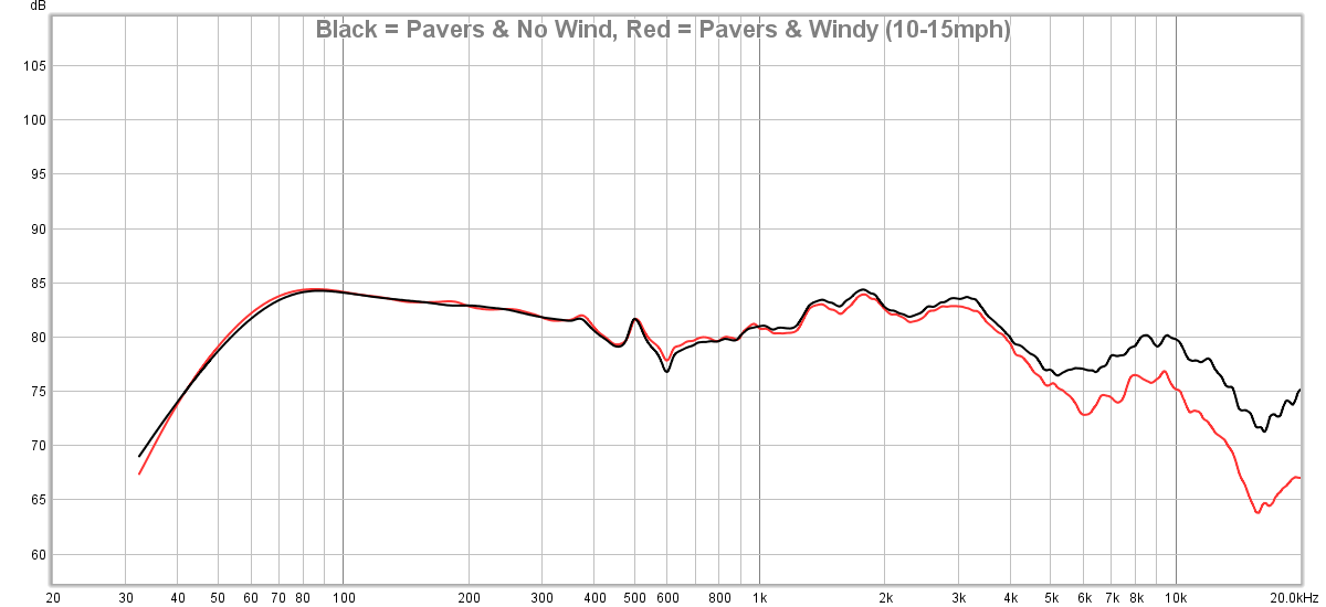
From what I'm seeing in all my tests this is what I feel comfortable with and how I will conduct my tests (barring no friends suddenly revealing they own a basketball court):
Measuring in driveway (or otherwise large, flat concrete area).
Mic flat on ground.
Speaker titled toward microphone to line up the tweeter axis with the mic.
No wind.
I think that would alter the baffle step contribution.
Please, allow me to vent...
Yesterday the weather was nice. No wind. The neighborhood was quiet. So, I set out to measure the S400 and get it done. I ran horizontal and vertical measurements. About 30 total measurements.
But, I made a stupid mistake. Given that it seemed the "mic angled down" measurements were a close match to what was expected, I decided to go this route but I made a foam "shroud" to prevent any reflections from the mic holder altering the result. Like so:
My mistake was: I didn't test the 'shroud' first. So, I completed all of these measurements, went and looked at the results and saw this:
Man, that is a LOVELY sight to see. Look at that high resolution! Oh, but wait.... Above 3kHz the data is junk!!!! Sonuva!!!!..
So, today I measured in the garage (ground plane, 2 meters, gated to about 8ms): 1) with shroud and 2) without shroud. The "with shroud" reduces output above 3kHz by about 1-1.5dB.
I am about to lose my ever-loving mind here.
I really want accurate data out of a single measurement (ie, no 'splicing' or 'blending'). My issue with splicing is it requires nearfield measurements of each woofer/vent and results in a nearfield bump. My issue with blending is it requires additional modeling that would also increase lead time. Plus, there's the concern that you really can't just assume a NF mic measurement of the different sources will behave the same off-axis; especially when you don't have high resolution due to the window size. And then imagine splicing a single NF set of measurements with multiple off-axis measurements. But from this little bookshelf alone I can already tell you the polars wouldn't be correct and the resolution/accuracy in the midrange would also suffer. Proof? Look at my above set of horizontal measurements; see the split begins about 100-200hz? On-axis NF + FF stitching won't show you that. I want that data.
A single ground plane measurement would give me data down to < 30Hz; that's resolution better than some anechoic chambers. It also means no need to blend or splice. That also means there is less chance for error in complicated enclosures where there are different sound sources on different sides of a large enclosure (ie, woofer on front, vent on back). Cons of the ground plane measurement are simply that it is outside and I have to contend with weather and neighborhood kids. Not to mention having to walk 40 feet to go turn the speaker (and I have played with different automated designs but they all elevate the speaker on a platform which only alters the data).
I have one more thing I want to try. If that is no bueno I'm gonna have to really think this over and consider the pros/cons of the above. I keep falling back to the driveway ground plane measurement but again, that has its own set of cons. I think my only solace in all of this is that "if it were easy, everyone would do it". I just didn't realize how much legwork I was going to be putting in to get confidence in my measurements. I almost wish I didn't know what the data should look like. I tell ya', ignorance is bliss, folks.
If any of you think I am being too complicated about this: I am. I know it. But that's because I want this data to be accurate. I could easily do some 5ms windows in my garage, do some NF measurements, slap 'em together and call it a day. And that's not a knock against others who don't have a choice but to do that. It is simply that I know I can do better... but how badly do I want to do better is the real question. Hey, if nothing else, maybe I can help you guys avoid the same mistakes I am making.
/rant
Was the inside garage ground plane was not enough distance compared to the driveway?
Well, you'd have to rotate the mic about the speaker. Turning the mic would just give you a response based on the mic's off-axis response which isn't the same as the response based on the speaker's off-axis response. And moving the mic around the speaker in a radius physically means you're moving further than you would if you just rotated the speaker.
Also, if you were standing near the speaker or the mic you would act as a reflection point. The further you are from either the mic or the speaker, the better. Ideally both are free of any barrier/wall/etc by the same amount. Since the window time is only as long as the closest reflection, you want both the speaker and the mic to have nothing nearby when measuring.
Inside the garage only got me about 5 or 6 milliseconds which was about 200hz or so. Give or take. But outside I can get down below 30hz. That means a resolution of 30hz. So, at 30 Hz, 60, 90, 120, etc I would have a data point. Whereas in the garage with 200hz I would only have a data point at 200, 400, 600, 800, etc. You can see why this matters a good deal when you have areas in between those data points that are doing funny things. For example, look at my above plot that shows a high-Q peak at about 500hz; a 200hz increment measurement would not show that as anything more than a small blip. But with 30hz resolution, you can see that pretty dang well.
My driveway slopes at quite an angle to the road, wonder how that affects....
I can't say how the slope alters the result. I can just guess that it would... but how far away the slope starts from the point where you are measuring and how steep the slope is would matter. Might be best to find an empty parking lot some day and measure there. Then measure at home and see what the difference is.
Also, you might want to read this:
http://www.artalabs.hr/AppNotes/ARTA%20Handbook%20Version%202.4%20English.pdf
[quote]There should be no reflecting obstacles in the measurement area. The distance from the source (speaker) to the next obstacle should be at least five times the measurement distance. This ensures that the level of any reflection is reduced by at least 20dB so that less than 1dB contributes to the overall sound pressure[/quote]
At this point I am pretty sure most who were paying attention have probably "checked out" at this point in the whole "how am I going to measure speakers" discussion but I'm going to make one final post on the topic because I had to feed my own curiosity...
To recap where my mental state is:
Driveway ground plane measurements look quite good. They make life a bit easier because there is no need to stitch. But they do come with cons (I'll cover this later). The only issue with GP in the driveway is neighborhood kids and other random things causing distractions when I am measuring. The backyard would be ideal but as I discovered in earlier tests, the grass is too absorbent and even a 2x8 foot section of plywood wasn't enough. I either need a large concrete pad or some other area of reflective surface. As a "last ditch" effort of trying to make the backyard GP measurements work, yesterday I went to Lowe's and purchased 3 large sheets of plywood. The idea was I would try them laying in the backyard as a "large, flat, reflective surface". I could have purchased more but I thought if 3 isn't sufficient to do what I need I might as well just stick with the driveway if I am going to do GP measurements.
First I had to wet the sheets down because they were bent. I learned this trick from my skatepark/ramp building days. Wet the concave side, lay it on the concave side. I let it set overnight. This morning they were all mostly flat.
Then it was on to testing. I tried ALL sorts of configurations between measuring longways and sideways. Here's some random photos...
But, I'll spare you the results of EVERYTHING and get to the point more quickly:
First up, let's look at the data from placing the mic on a single sheet of plywood vs the "bare ground" I took a couple weeks ago vs the (windowed) ground plane measurement I conducted in my garage:
As you can see, there is some improvement in the high frequencies when using the single plywood sheet compared to the bare ground measurements. Notably, with the plywood the HF response no longer has a sharp dip it did in bare grass. But, the plywood measurement shows a dip between 100-300hz and compared to the garage GP mesurement the HF response is still not what it should be; down by about 2-3dB above 1kHz.
What happens when I add a small piece of OSB behind the mic (Purple) and then as another test I add a small sheet behind the microphone as well (orange)?
Practically zero difference when placing the small section of OSB behind the speaker and then both the speaker and the mic.
No point wasting time doing that. But, further results will all have both these scrap OSB pieces in the measurement.
Okay, so what happens when I add a second sheet of plywood to the side (brown)?
What about adding a 3rd piece of plywood to the side, with the speaker/mic in the middle (green)?
What about shifting the speaker/mic off to one piece of plywood (purple)?
Moral of this story:
Don't bother wasting money on plywood thinking if you create enough surface area you'll get accurate results. Maybe if you buy a LOT of plywood. Maybe. But then you have to take it up and put it down for test. If you want to do ground plane measurements you need a LARGE, FLAT, concrete area. I wasted $60 on this experiment but at least I know now. So, let me save you money: Don't waste your time doing what I did with the plywood. As you can see it doesn't fix the issue entirely.
(now, maybe I could 'calibrate' the measurement for this plywood but I don't trust that.
Since I was in my backyard I thought ... might as well go ahead and throw the speaker back up on the platform and test there to see how the ground plane garage measurement compares to the 4pi "free space" measurement at 36 inches. After adjusting level differences (36 inch vs 2 meter/GP), you can see the two are practically identical!
And then I took another measurement from 12 inches:
The nearfield gives a bit better resolution on the lower end at the *potential sacrifice of the accuracy in the 1-2kHz region.
*This could be aiming; I wasn't being critical about being "dead on" to the tweeter in these tests; just getting close enough to see what difference the trend showed, if any.
Moral of this story:
Ground Plane measurements can, indeed, yield highly accurate results identical to their 4-pi counterpart. And it is a whole lot easier to place a speaker on the ground than it is to hoist it 8+ feet in the air.
Let me update and then I'll answer this question shortly...
After sleeping on this I have decided that merging Low Frequency with High Frequency data (similar to NF/FF merging) is the only way I will be able to do this and provide the data to the accuracy I desire in most cases. That means I will have to measure ground plane both indoors and outdoors. (If I happen to have really nice weather conditions where the outdoors measurement results in the same HF response as indoors then I won't bother at all with splicing).
Now, there are options to merge the data: using the various software available (virtuixCAD, DIY'rs excel sheets) or I can use Klippel's script. However, this all requires me to merge one at a time. To get vertical and horizontal data, that's merging about 60 files down to about 30. That would be agonizing (and most importantly, prone to accidental error). So, I wrote a script in Matlab to do a "hard splice" in a batch. I provide it all the files, tell it where I want the splice to be and it calculates the delta and makes the low frequency graph merge to the upper frequency; same premise as NF/FF merging. I am ignoring phase for this aspect and focusing solely on the resultant FR. The plan is to measure all angles... I'll have to do it twice: in the garage for mid/upper and outdoors for lower. But once I do that, I can load the FR files as txt and my script will take care of the rest and throw them all on a plot. I have another version for a "soft splice" which will try to blend data points but for now the hard splice method works well as long as I choose a frequency where there is good consistency between trends (and I have the data resolution to support it).
Edit: It was pointed out to me that virtuixCAD will do what I want but I still think I'll rely on my own script since I can just reference a folder and call it done.
This is what the result for a single axis looks like (the script will automatically populated all measured axes as needed but I only fed it a single axis for now):
For the time being I have provided the output of my combined LF/HF merged data with that of ASR's as well as Buchardt's NFS data. My result is right in between theirs. And, therefore, IMHO, certainly acceptable. Take note that I have provided two of Buchardt's NFS results: one is "original" which was measured before they implemented a slight crossover modification and the other is the "updated" which was measured more recently with the modification in place.
I still need to resolve the turntable aspect to save me time of turning the DUT manually. Making the center of rotation at the baffle creates some challenges when you have a turntable that is built with the platform an inch or two above the ground; you get a baffle step effect from the lifted platform in addition to reflection from the platform itself. I've got a couple ideas to try. I'll post on that later. If all else fails, I'll just use a piece of cardboard and turn the DUT manually as I did earlier this week.
At any rate, I'm making forward progress. Yay!
Okay. I used my script to run the horizontal polars. Looks pretty darn good.
I'll have to clean up the script but I am happy with how it works so far. I have it set up to where I point Matlab at the directory and it prompts me for the stitch frequency, I tell it where, then it dumps out the following plots. I'll have to add info for verticals. Then there's the impedance/phase, IMD, max SPL, and other tests. But I think I finally have decided on how I am going to test and the scripts will help me automate the presentation of the data so I can focus on the analysis aspect.
I am going to try to recap everything I have learned thus far.
As we know by now, there are many ways to measure a speaker's response. All with their own pros and cons. My efforts reveal that a 2-pi ground plane measurement can give the same accuracy as a 4-pi "speaker in the sky" measurement. And it's a lot easier. So I will measure in the garage for mid/high frequency accuracy and outdoors as needed for low frequency stitching. As for rotating the speaker, I built a turntable using a NEMA-23 motor and a USB stepper motor controller but the platform height is currently of concern. I'll work through this. If all else fails I'll manually rotate the speaker. It's easier to do this than it is to wait for the perfect weather and rig up a heavy speaker high in the sky. That's the method I choose. If others choose to use the 4-pi speaker on a stand method that's fine. Again, both are fine methods.
However, it is worth noting that in my garage using the Ground Plane method I can place my DUT and mic in the center of the garage, clear items out from the sidewalls and get about 11ms free of reflection window as you can see at the bottom of this post. This is significantly better than if I were to place the speaker on a stand in my garage and measure; at which point I would get about 4ms of reflection-free time (due to the floor and ceiling in my 10 foot tall garage space). That's the difference in having a data point approximately every 90hz (11ms) vs every 250hz (4ms). And for no other reason encourages one to at least consider a proper ground plane measurement in lieu of the standard 4-pi method.
The thing to note about ground plane measurements are they need to be in an area that is obviously far, far away from the nearest boundary (wall, vehicle, etc) if you want low frequency accuracy (same as any other method). And it also needs to be in an area that has a large reflective surface. You don't need a mirror (as I have shown). But concrete is necessary and grass will not cut it (ha! no pun intended). If you are looking to perform LF response only measurements and all you have is an open field to measure in, then you can probably get away with 300hz as the maximum range (my data shows 400hz in my backyard with very low cut grass). I would not trust the data higher than that, however. Plywood is NOT a good substitution.
Any measurements performed outdoors need to be performed when there is practically no wind. A little wind is tolerable but more than a couple mph and the HF data is corrupted and considerably moreso if the wind is higher (as I have shown).
And, finally, these are all just my results. I encourage you to do your own tests if you have the desire to measure your own loudspeakers. Let my results guide you but understand that different surface areas and conditions will effect the results and you need to quantify those differences before you go willy-nilly with measurements. I have seen a lot of measurements since I started this quest that make me question the accuracy and reliability because of the knowledge I have gained from my own testing of the different methods. But, such is life. As long as you understand what you're doing and you can back it up with data then you can better provide analysis.
Hopefully some of you gained some useful information from this. I know it has been enlightening to myself for sure.
- Erin
Ground Plane Impulse Reflection-Free Window ( ~ 11ms wide; 90hz data point intervals; mic 2 meters from DUT)
Stand Mounted Impulse Reflection-Free Window ( ~ 4ms wide; 250hz data point intervals; mic 1 meter from DUT)
Here's some information for those of you who may want to conduct their own measurements with the ground plane method. (@Kornbread)
I've mentioned it numerous times but in case someone didn't catch it or doesn't already know: when you measure a speaker in the ground plane you need to tilt the speaker some angle in order to line up the speaker with the microphone axis. This is covered in various places online and discussed in D'Appolito's "Testing Loudspeakers" book. It's a pretty simple tangent equation but there are calculators online to make this easy for you. Here's one: http://www.mh-audio.nl/Acoustics/Groundplane.html
You enter the mic distance from the speaker and the distance from the ground to the tweeter (or other reference axis; say, midpoint between tweeter and midrange). This site recommended using your phone in "selfie" mode to make sure the microphone shows up in the center of the image. I do this from time to time to sanity check the calculations. You can see my 4th image below displaying this method.
Now, what I've read before is it is OK if you are off a little bit. But I thought it would be helpful for me to show just how much the tilt angle matters so in this example I am using the same Buchardt S400 in my garage.
First I used a laser level to draw a line on my garage floor to make sure the microphone was on-axis with the speaker. I also used a distance finder to make sure the distance was at 2 meters.
**
Side note, if you are interested, these are the two items I use and am quite happy with them. About half the price of the hardware store versions. If you plan on doing GP measurements in your garage, these will make your life so much easier and improve accuracy of your aiming/setup. I recommend you buy them. If not these, something along these lines. The links below are made with my Amazon affiliate link so if you do purchase them I'll get 2%... hey, every little bit helps.
Laser Level
Laser distance finder (bonus: this thing has an angle detector which is perfect for determining speaker tilt angle)
**
Anyway, here's some photos:
Now, keep in mind the Buchardt S400 has a 2 degree tilt on both the baffle and the rear. Literally, it looks like a parallelogram instead of a typical box enclosure.
1) The first test was ran with the speaker bottom flat on the floor; not tilted forward. (Red)
2) I then used the site above, entering the distance as 2 meters and the tweeter height as 4.5 inches (~ 10cm). I got a suggested tilt angle of 2.90°. I thought, hey, let's overcompensate here and also add the 2° tilt from the enclosure itself, so I came to 4.90° total. Therefore, the actual angle of the baffle perpendicular to the floor was now 2.90° (4.90°-2.00°). (Blue)
3) I then remeasured at 2.90° (no factory tilt accounted for) and the actual angle of baffle perpendicular to floor was 0.90° (2.90°-2.00°). (Green)
Here is the result.
You can see there is indeed a notable difference in the 2-4kHz region between the 3 measurements (and a smaller difference from 5-8kHz). I think this can be telling of the best axis to listen on but that's for a different time. For now, the point is: the tilt angle even within 5 degrees has approximately 3.0dB difference at about 3kHz. And the 0.9° vs 2.9° difference at 3kHz is approximately 1.5dB.
What does this mean? I think it means that care should be taken to ensure the intended axis of measure (the tweeter, between tweeter/mid, etc) is used as the reference plane and the speaker tilted as necessary to make this so.
Obviously, YMMV (your mileage may vary) depending on the speaker, distance, etc. But I would urge you to take care to make sure the tilt angle is correct before you continue with the measurement process.
- Erin
It was asked on DIYA so I am sharing it here...
[QUOTE]Sooo, to me, the main take-home message of your tests is that the ground-plane method easily yields consistent results at low frequencies, up to 500 Hz or so. Normal indoor gated measurements will go down to 300-400 Hz (anechoic). The ground-plane measurement might therefore be a useful method to extend this low frequencies (that's what the theory always told us, but now we KNOW).[/QUOTE]
Yes. But to reiterate, it makes more sense to perform an indoors ground plane measurement instead of the speaker-on-a-stand measurement for the reasons I listed previously. At least for me.
[QUOTE=mbrennwa;6198828]Sooo, to me, the main take-home message of your tests is that the ground-plane method easily yields consistent results at low frequencies, up to 500 Hz or so. Normal indoor gated measurements will go down to 300-400 Hz (anechoic). The ground-plane measurement might therefore be a useful method to extend this low frequencies (that's what the theory always told us, but now we KNOW).
This leads me to the following questions and ideas:
Would it be possible for you to take some nearfield and mic-in-box measurements of your speaker, and compare these to the ground-plane measurements?[/QUOTE]
The DUT I have been using is one with a passive radiator so I cannot perform the MIB test. However, I had previously captured nearfield response of both the woofer and the PR.
FWIW, I am using the sd of these drivers (as they appear to be the same ones used in the Buchardt S400, with assumed differences in electro-mechanical properties; however the physial dimensions are almost certainly the exact same):
https://www.madisoundspeakerstore.com/approx-5-woofers/sb-acoustics-sb15sfcr39-8-5x8-paper-cone-woofer/
https://www.madisoundspeakerstore.com/approx-5-woofers/sb-acoustics-sb15nbac30-4-5-black-aluminum-cone-mid-bass/
With the above stated, the nearfield method has a maximum frequency accuracy dictated by the size (as discussed in the above audioexpress link). The 5" woofer is limited to about 980hz and the 5x8 inch passive radiator I will limit to the 8 inch dimension and therefore is invalid above about 600hz. Just spit-balling here; not using the actual effective radius. But it's close enough.
... On with the results. ...
As you may know, when capturing near-field data it's hard to get the exact same level relative to distance of mic from cone and therefore the result is usually "eyeballed" to overlay them together, by using the lowest frequencies. I have done that below. What you see below is:
*Note the y-axis scale is 10dB. Using 5dB is too hard to read.
And here is the summed nearfield response above vs my ground plane (at 2 meters) measurement:
Understanding, of course, I had to "eyeball" where to overlay these in frequency, you see the presumption regarding NF responses showing a bump in the low frequencies due to the fact that it effectively ignores baffle step is indeed true: the 2 meter ground plane measurement is lower in amplitude on the low end than that of the NF components & summed response. This is to be expected and you can find the following quote on why stated in the above audioexpress link:
[quote]First, Keele assumes all radiating surfaces are mounted on an infinite baffle. Under this condition, the radiation is into a “half-space” or a solid angle of 2π. However, most loudspeakers have relatively narrow baffles so they become omnidirectional at low frequencies. For this reason, the Keele approach may over estimate the low-frequency sound pressure level. [/quote]
The farfield ground plane technique is more accurate as you can see (and as was expected). The NF summing technique gives you an idea of the low end response but isn't entirely accurate to that of a far-field response AND it requires care in the measurement, assumptions and final calculation. Honestly, I prefer the ground plane measurement method simply because it's less prone to personal error. Meaning, the more ports and woofers I have to measure individually and then add together, the greater chance for a human error to occur. Whereas a ground plane measurement is just sticking the mic a few meters in front of the speaker, running a sweep and then you're done. I would only use a nearfield method if I had no other choice due to area available or terrible weather.
[QUOTE=hardisj]I had someone PM me to ask if I modeled diffraction in the above NF summed response results. I think it's a worthwile question so I'll share my reply here as well:
I did not. [/QUOTE]
Ughhhh.... Ok. Curiosity got the best of me. But I swear, I AM DONE after this!....
Now, let me state: I have never used VituixCAD for this purpose but I *think* I did this correctly...
I opened the Diffraction Tool.
I loaded my NF curve in the Half space response section
I checked "full space"
I modeled the enclosure with the woofer in the appropriate place on the baffle.
I modeled the microphone about where the tweeter axis is.
I set the mic distance to 2 meters.
I saved this response.
I repeated the same process for the passive radiator (using a rectangular driver since it's an oval).
I then used VituixCAD's Calculator Tool to sum the those (2) curves. What you see below is a comparison of the original 2 meter far field in Red vs the different NF sums. In blue is the summed woofer & PR response *WITHOUT* diffraction modeled. In black is the summed woofer & PR *WITH* diffraction modeled.
As I posted previously, the simple NF sum of the woofer + passive radiator (blue) shows a boost on the low end that was expected. HOWEVER, if you apply the diffraction effect to each of the components and then sum them (black) you get a combined response that follows the 2 meter GP measurement (red) quite well. Close enough, in fact, that I would feel comfortable using this method in future tests if I don't have the ability to physically measure outdoors to get the LF extension in response I need. It isn't perfect but I think it shows the necessity for modeling the diffraction effects for those of you who are dealing with how best to accurately gather data for your reviews or your own designs.
Okay. That's it! I'm done!!! I have to quit obsessing over this topic. Thanks for joining me in this journey. But I've gotta bail. I'm out of money and I'm out of sanity!