How long can the XLR microphone cable be that attaches to the Steinberg UR22 MK II to the measurement microphone? I am thinking that I need a minimum of 15 feet when doing SPL speaker measurements, but I would like to maybe use a 25 ft cable just in case I need a little extra reach. For the other two TRS cables (REF and IMP), I am going to make them 5 feet each.
Bill, when I ran live sound we used 25 Ft and even 50 Ft mic cords all the time, plugged into a stage snake that is another 150 Ft long back to the mixing board. That is one of the many benefits of phantom powered, balanced, XLR cables and connections. And it wasn't just our Shure SM58 mics. Musical instruments plugged into direct boxes were just as clean/quiet. Then when we switched from our VERY nice Yamaha analog board to our X32 digital board the noise floor dropped even further. It allowed us to get rid of tons of analog gear (gates, compressors, EQs). Sorry for the tangent.
I use a 25ft cable. Get a proper microphone cable with soft rubber/silicone jacket. Cheap junk XLR cable with PVC jacket will just leave you frustrated as it won't lay flat and keeps pulling on your mic.
A condenser mic is literally a small capacitor. A small capacitor connected to a long wire would interact with the small capacitance and inductance of the wire. The phantom power serves 2 purposes. First is that the condenser needs to be "charged", as well in the mic there will be a sort of buffer circuit for signal transmission without any interaction between the cable impedance and the condenser capsule.
Quick interweb search found this image which is a good description of what's really in a condenser mic.
Fed Ex shipment arrived today. A few unboxing pics:
I can now install the missing Neutrik jack:
The mic came in a nice padded case, but no manual or calibration file. I downloaded the calibration file by going to Sonarworks.com and entering the mic ID number:
The Steinberg UR22 MK II box included a software installation disc and printed manual:
Rear panel of UR22:
UR22 sitting on top of Arta jig. Almost done, just a few more wires and solder joints to go:
First step with the UR22 is to take the "mix" knob and turn it fully clockwise pointed at "DAW", then never touch that knob again.
Doesn't look like that mic came with a mic clip. That's too bad, and the cardboard box is kind of lame, so it looks like Dayton has a leg up on accessories.
@dcibel said:
First step with the UR22 is to take the "mix" knob and turn it fully clockwise pointed at "DAW", then never touch that knob again.
Doesn't look like that mic came with a mic clip. That's too bad, and the cardboard box is kind of lame, so it looks like Dayton has a leg up on accessories.
"mix" to "DAW" ---> Done. Nope, no clip. I didn't use the cheap plastic clip that came with OmniMic because the clip did not hold the mic firmly. Instead, I mounted the mic toward the end of a long piece of 3/4" diameter oak dowel rod. My plan with the new mic is to do something similar in an effort to minimize reflective measurement contamination. That will be my next project.
Bill, if you get a chance, can you take a picture of the power cord for the Steinberg? I got one used on eBay right before I moved. I didn't really check at the time, so I don't know if it didn't come with a cord or if I have the cord in one of my boxes full of cords from the move.
@a4eaudio said:
Bill, if you get a chance, can you take a picture of the power cord for the Steinberg? I got one used on eBay right before I moved. I didn't really check at the time, so I don't know if it didn't come with a cord or if I have the cord in one of my boxes full of cords from the move.
The box only contained a type B USB cord, as show in dcibel's photo above. The Steinberg is powered from the 5 volt supply coming down this cable from your laptop (or desktop). There is also a 5 VDC power input jack and a switch on the back of the Steinberg that can be used to switch from the USB cord over to an an independent 5 VDC power supply. The cable (and wall wart transformer) necessary to do this was not supplied in the box.
Which brings up another question. Would it be beneficial to build an independent, low noise, regulated 5VDC power supply to power the Steinberg? The 5 VDC supply coming from the laptop probably has a fair amount of switching noise on it.
I have zero concern of noise with the interface, I'd imagine it has a little buck converter / regulator / filtering all built in making the quality of the incoming 5VDC irrelevant… the micro USB plug AFAIK is so that you can power it externally while using a mobile device like tablet for recording. For PC or laptop connection, just plug in the big USB type B connection and be done with it.
Of course you can measure the noise performance yourself with ARTA or RMAA for an automated test, just loop the output back to the input and measure away.
I finished up the jig this morning and snapped a few more pics.
Since 4 of the Neutrik TRS pins are tied together (1+3+1+3 or GR+R1+GR+R1 or S+R+S+R), I installed a 3" long grounding bus bar through all 4 jack holes and then soldered them all together:
I then connected all the remaining parts or wires to the grounding bus bar on one end and to the appropriate circuit node on the other end. The lower Neutrik TRS pins are the tips (pin 2 or pin T). They connect to the 47K/22K junction nodes on the center terminal strip with two short red wires.
I also installed a short black wire from the bus bar to a single star ground chassis lug. This grounds the metal jig chassis to the soundcard's reference ground. The amplifier ground, on the other hand, is not connected directly to the chassis. Instead, it connects to the bus bar through a 1K resistor, as outlined in the schematic. As dcibel explained in another thread, this resistor is designed to eliminate a possible ground loop between amplifier and soundcard.
Here are a few more angle shots, so you can see the wires routed behind the terminal strips a little bit better:
Next up, I'll install the Steinberg's drivers on my laptop and test out the soundcard. Then I'll try a simple loop back test, without the jig, to see if Soundeasy will measure a flat line without error. Fingers crossed.
Oh, I forgot to mention. I did a continuity check of the 3 Neutrik TRS pins against the metal mounting shell. None of the pins connect directly to the shell casing. So, my short black wire connecting the bus bar to the metal chassis is the only ground connection to chassis. This forms an electromagnetic shield over all the internal wiring and the Neutrik TRS shells.
The biggest thing with SE is that it uses old WDM audio, so you have to make sure that windows audio settings match the bit rate and sample rate in SE or all hell breaks loose. ASIO is much more plug and play if you ever decide to jump ship to ARTA
I had problems with SE at 192kHz as well, so 96kHz was the limit. I also helped write the SE instruction for VituixCAD so let me know if you have questions once you get there.
Thanks for all your help, dcibel! Yesterday I downloaded the demo version of Arta and loaded it onto my laptop. So I will be testing both packages as I go along. I'm on the fence right now, but I will probably end up purchasing the Arta license.
I've been working on a document providing some basic instruction on how to set up and use LIMP for measuring driver impedance and T/S. I'll post it here as it may be of some help to you, but I don't consider this document complete yet. I was planning to expand it with some example screenshots, and provide some detail on measuring components and assembled filters as well.
I'm fairly certain that you can do everything required here in LIMP in "demo mode". The paid license really just unlocks the ability to save impulse response files with ARTA.
My initial loopback test, without the ARTA jig in circuit, appears to be successful. If these screenshots look OK, then I think it is safe to say that I have the soundcard, the soundcard driver, and Soundeasy preferences set up properly to work well together. If so, I will proceed to the next phase and attempt to measure a simple resistor with the ARTA jig in circuit.
Here is the Steinburg UR22 USB driver screen. I installed this driver on my laptop using the CD that came in the box:
Overview of loopback cable setup. The front panel channel 1 & 2 line inputs connect to the rear panel channel 2 line output via two 1/4" TRS cables. A DIY "Y" connector combines channels 1 & 2 at the output (rear) end of the cable:
Close up view of my DIY "Y" connector, cobbled together from junk box parts. I was going to make my own 1/4" TRS cables as well, but I switched gears and picked up a pair of "Roland" brand cables from a local Guitar Center:
Soundeasy MLS measurement screenshot:
Finally, here is the Soundeasy preferences screen. I am showing this screen because Soundeasy sometimes changes the soundcard selection in preferences based on what the user enters over on the MLS measurement screen. So I had to go back and forth, re-setting the soundcard in preferences, otherwise SE would kick out an error whenever I tried to run MLS (ie., "A device ID has been used that is out of range for your system").
Oh that's right, the UR22 driver is clever enough that it takes control of the windows settings. The settings in the windows sound control panel are greyed out, because they are only controlled through the very simple driver interface.
You 100% need to uncheck the "enable loopback" in the driver settings. Always unchecked.
The UR22 only operates in 24bit mode, so I would select 24 bit sound card in the SE preferences. While you're in the preferences, 5-50kHz system frequency might make more sense than 100kHz given the 96kHz sample rate. SE is a major pain if you ever want to change the frequency range of the plots, so pick it once and never change it would be my recommendation.
I'm not really understanding the need for the "y-cable". Soundeasy sends the test signal out of both channels, as long as the "both channels" checkbox is enabled. Of course for normal testing only one channel of output is required, so the y-cable is a bit confusing to me. For my purpose of connecting the UR22 to an amplifier, I just use mono TS to RCA adapters, and then use a regular old RCA cable to the amp. This works just fine and avoid needing a special cable just for this jig setup.
In the MLS measurement settings, you have the shortest MLS length selected, I would usually select the longest length for maximum resolution. SE also doesn't have a setting to disable the windowing, so a 5ms window is not really what you want to interrogate frequency response down to 20Hz. It must be set less then the MLS length of course, so the numbers get a bit hairy here. The MLS length is in samples, so the maximum length is 262142 samples, at 96kHz that's 2.73 seconds. With this in mind, window of 1000ms is more than enough to reach the 20Hz goal with accuracy. The window width in samples will be the number above the time in milliseconds.
It doesn't matter for this purpose, but for real gated measurements I would want to select the window type as Hanning, not rectangular. The window type affects the low frequency roll-off of the gated measurement, so we want something that represents a smooth roll-off without overshoot or undershoot. You can expect much overshoot with a brick wall filter.
Of course if you are measuring for use with VituixCAD, none of the windowing settings matter as the impulse response will be directly exported and all processing done in VituixCAD, in which case I recommend the "cosine" window function there which is a very slight improvement over Hanning.
The loopback result is otherwise fine, as expected with this fine piece of hardware. The flag that the SE manual raises is to verify a perfectly flat response and phase here, as a phase error indicates timing error between the two input channels, but you should only see that sort of issue on junk equipment.
Just a note on what that "enable loopback" does in the driver setting, should provide good explanation of why it should be off for our purposes. You may find that your loopback test is a perfect success with the cables completely disconnected, but the option enabled in the driver settings.
Thank you both for the pics of the power cord. I had seen the 5v input and thought I might have lost a cord.
A few questions:
1) Are both switches SPST?
2) What does the optional SW2 (with C1) do? As it is optional, I assume it allows you to do something useful, but not critical, but just wondering what it does and when you would want to use it.
3) @dcibel - in the schematic moving left to right you have R5=22K and then lower right corner R5=1k...I assume this last one should be R6.
The cap and switch is just providing the option of putting a cap in series with the driver, so it is just a basic 1st order high pass filter to cut the bass frequencies. You may want one for testing delicate drivers like ribbons, optional as most measurements don’t need it, and if you don’t include it it’s still easy enough to simply put a cap in between the amp and the jig externally.
Thanks for all the great suggestions. I unchecked "enable loopback" on the soundcard driver screen. I also made all of your other suggested changes to the SE preferences screen. As luck would have it, I just happened to have two, unused mono 1/4" TS (phono) to RCA adapters in my storage cabinet. So, I'm good to go for the amp connection.
I used the "Y-cable" because I was following the instructions in John K's Soundeasy Design Guide, 4th edition, the section entitled "The loop Test Sound Card Check." I "think" I did it the way he describes it. Perhaps his instructions are outdated. So what you are saying is that I could have just used two 1/4" TS or TRS loopback cables to hook both inputs to both outputs and forget about the "Y-cable". Or am I missing something?
I also made most of your suggested MLS settings changes. Again, the values I had entered came from John K's Design Guide. I was just copying his suggested entries. I will re-run the loopback test with your changes and see what happens. Thanks again for all the great suggestions.
I used the "Y-cable" because I was following the instructions in John K's Soundeasy Design Guide, 4th edition, the section entitled "The loop Test Sound Card Check." I "think" I did it the way he describes it. Perhaps his instructions are outdated. So what you are saying is that I could have just used two 1/4" TS or TRS loopback cables to hook both inputs to both outputs and forget about the "Y-cable". Or am I missing something?
Yes, just use 1/4" patch cable from output to input. Maybe old versions of SE only output on the left channel or something silly like that. The test signal comes out both channels in any version of SE I've used, I think I started at v20. I think John's guide has you use a Y cable to be sure that the exact same signal is presented to both inputs. My thought is that we are testing the audio device for accuracy, which includes the outputs which should be equal as well. I have certainly run all my loopback tests without a y-cable.
I also made most of your suggested MLS settings changes. Again, the values I had entered came from John K's Design Guide. I was just copying his suggested entries. I will re-run the loopback test with your changes and see what happens. Thanks again for all the great suggestions.
I have the guide as well, but it's been a few years since I've read it. The values John suggests for the loop back test are a bit silly, but he is also running at 48kHz, and suggested a window width of 480, which is 10ms and represents a wavelength of 100Hz. Maybe not a big deal here since error in the loopback test should be observed at high frequency, but there's no need for it either, doing a high resolution ungated measurement is all of 3 seconds of your time.
At 96kHz, you would have entered a width of 960 to match his settings, and double the MLS length as well for the same time duration.
I had trouble getting SE set up properly to make impedance measurements, so I shifted over to the LIMP demo version to see if I could get that program working properly with my jig. LIMP is a much easier program to set up and I was able to quickly de-bug the problem and get it going. Basically, I initially had some of the cables connected in the wrong positions AND I had accidently pushed the "Input B / High Z" in when I was connecting cables. This button must be left in the "Off" position (out) to properly calibrate the two channels. If this button is accidently pushed in, it throws the balance between the two channels way off and totally messes up the measurements. Sorry for all the detailed screen shots below, but unless you cross every "T" and dot every "I" the system will not work (as I found out).
First off, here is a pic showing all the cable hookups for measuring the T/S parameters on a Dayton ND90-8 driver. The only connections "off camera" are the two cables running off the right side of the laptop keyboard. The power amplifier is directly underneath this long board and these two cables are the RCA cable going to the amp's inputs and the speaker wiring coming back from the amp and going to the back of my jig.
Here are 3 screen shots showing the LIMP soundcard setup:
Here is the LIMP measurement setup screen. Note that I changed the default 100 ohm resistor value to the 9.87 ohm resistor that I used (measured on EX 530 meter less cable resistance, accurate to about 0.3% per the manual). Also note that I changed to the left channel output selection, which corresponds to output channel that I actually used.
LIMP calibration screen. Note the position of all UR22 front panel gain and output controls were roughly in their middle positions to achieve this balance. The probes were disconnected from the driver to perform this calibration.
LIMP overlay and frequency shift screens, showing how putting two nickels (10 grams) on the ND90-8 cones shifted the Fs down by 47.7"
LIMP calculated T/S parameter screen verses the DATS V2 screen for the same driver and added mass. The results are very close, which indicates that my jig is probably working properly:
Next up, I'm going to shift back to Soundeasy and see if I can replicate these results by correcting the hookup and "Input B / High Z" mistakes that I made on the first go round.
Well, you haven't followed the instruction I posted above to a T, but close enough, you have a perfectly well functioning jig from the looks of it.
Of course high Z should always be off, we are recording "line level" not a guitar pickup . This button will change the input impedance from 20kohm to 1MOhm, so you can guess how that might change some interaction between the probe resistors. There was some detail to this effect in my response to John a few posts back when he was asking about his Behringer UM22 where one input is high Z only.
Similar to the loopback test you ran in SoundEasy, one neat thing I like to run in ARTA is a simple jig loopback test.
Connect the jig to your amp, but without a speaker connected. Connect both reference and impedance probes, however select "SPL", which effectively connects both probes to the amp output.
In ARTA, select FR1, then setup the measurement for 192kHz sample rate.
Another option I usually set here is to right click on the chart and set 1/12 octave smoothing.
Input of left or right won't matter here, this is a single channel measurement and we've looped back both L and R channels. Then, select "PN Pink" under the generator dropdown, and push the red play button. Adjust the frequency range to show from 10Hz to 100kHz and you should be observing the frequency response of the chain from UR22 to amp and back through your probes. For this screenshot I used an "antique" Realistic SA-1000, more modern equipment will probably be a bit flatter at the lower frequencies.
You probably don't need to do this, but you can check both L and R input to verify that you get the same result with both probes, just to verify that there are no wiring mistakes.
Next step demonstrates the wonders of a 2-channel measurement. Select FR2 and do the same thing. Here you should see a flat line, near 100kHz we have not enough signal to get a measurement. The frequency response of the equipment has been compensated for by normalizing one channel input to the other. Even though the measured frequency response is not completely linear, both inputs measure the same thing, so there is no difference, hence a flat line.
If you want to see how the transfer function of how the "protection cap" interacts with a driver, you can do the same with a driver connected and the high pass switch turned on.
The FR1 response will show you the transfer function of the capacitor inserted:
For a dome tweeter there is some peaking as you can expect with a single component filter (this was an XT25 in a waveguide). 50uF cap may be a bit much in retrospect, cutting that in half should be fine.
The FR2 response should still provide you with a relatively flat line. On my end I show a 1dB bump around 500Hz which is interesting, as the only real difference between the two probes is the inclusion of a switch, a couple inches of wire, and differences between the tolerance of the probe resistors. I'm not too concerned anyway, the normal use case for this measurement would be reference vs mic input, and for impedance measurement in LIMP, the probe tolerance is removed through the calibration process.
I've also just decided that an a receiver with speaker A/B selection is ideal for a setup at your desk. You can leave the receiver connected to your desk speakers on the A terminals for every day use, and leave the B connection to the jig, then just select the B speakers when you want to measure something. It also provides you the ability to disconnect the amp from the jig without turning it completely off.
Good stuff. Will give your Arta loopback test a try. Looks like I completely missed your 96kHz sample rate and lead compensation instructions for LIMP. I'll go back and make these changes. My mind was really "burned out" yesterday when I set this up because I had just spent several hours fighting with Soundeasy. I think I know what I was doing wrong, so I'm going to give that program another try later.
No problem, the lead calibration is generally making very small changes for driver measurements, but if you are measurig small resistances of inductors and want accurate DCR then I'd absolutely recommend going through the lead resistance compensation process.
FWIW the documentation for SE doesn't say this specifically, but you can run the calibration in SE in exactly the same manner as you do in ARTA. Just disconnect the load and hit the cal button. Make sure the gain of each input is set roughly the same, SE will complain if the 2 input channels have significant difference in level.
Comments
How long can the XLR microphone cable be that attaches to the Steinberg UR22 MK II to the measurement microphone? I am thinking that I need a minimum of 15 feet when doing SPL speaker measurements, but I would like to maybe use a 25 ft cable just in case I need a little extra reach. For the other two TRS cables (REF and IMP), I am going to make them 5 feet each.
25 ft mic cable is not a problem.
Thanks, Craig. 25 feet for the win!
Bill, when I ran live sound we used 25 Ft and even 50 Ft mic cords all the time, plugged into a stage snake that is another 150 Ft long back to the mixing board. That is one of the many benefits of phantom powered, balanced, XLR cables and connections. And it wasn't just our Shure SM58 mics. Musical instruments plugged into direct boxes were just as clean/quiet. Then when we switched from our VERY nice Yamaha analog board to our X32 digital board the noise floor dropped even further. It allowed us to get rid of tons of analog gear (gates, compressors, EQs). Sorry for the tangent.
I use a 25ft cable. Get a proper microphone cable with soft rubber/silicone jacket. Cheap junk XLR cable with PVC jacket will just leave you frustrated as it won't lay flat and keeps pulling on your mic.
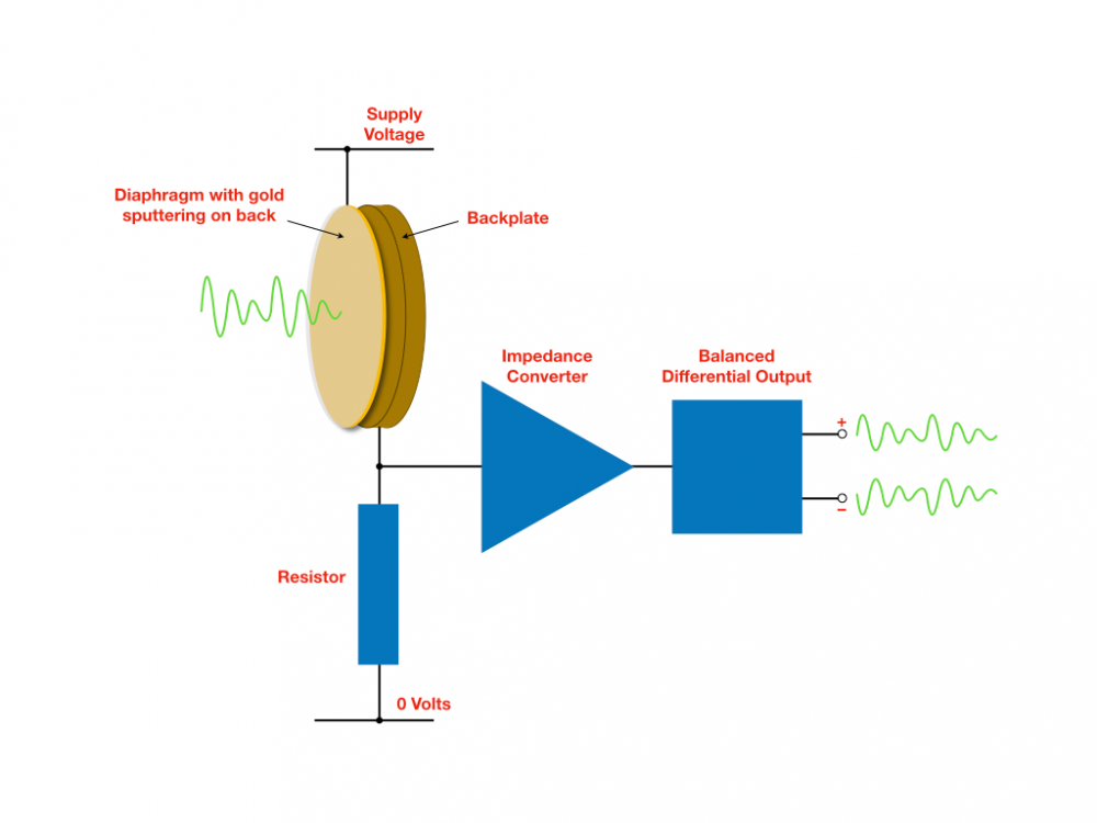
A condenser mic is literally a small capacitor. A small capacitor connected to a long wire would interact with the small capacitance and inductance of the wire. The phantom power serves 2 purposes. First is that the condenser needs to be "charged", as well in the mic there will be a sort of buffer circuit for signal transmission without any interaction between the cable impedance and the condenser capsule.
Quick interweb search found this image which is a good description of what's really in a condenser mic.
Fed Ex shipment arrived today. A few unboxing pics:
I can now install the missing Neutrik jack:
The mic came in a nice padded case, but no manual or calibration file. I downloaded the calibration file by going to Sonarworks.com and entering the mic ID number:
The Steinberg UR22 MK II box included a software installation disc and printed manual:
Rear panel of UR22:
UR22 sitting on top of Arta jig. Almost done, just a few more wires and solder joints to go:
First step with the UR22 is to take the "mix" knob and turn it fully clockwise pointed at "DAW", then never touch that knob again.
Doesn't look like that mic came with a mic clip. That's too bad, and the cardboard box is kind of lame, so it looks like Dayton has a leg up on accessories.
"mix" to "DAW" ---> Done. Nope, no clip. I didn't use the cheap plastic clip that came with OmniMic because the clip did not hold the mic firmly. Instead, I mounted the mic toward the end of a long piece of 3/4" diameter oak dowel rod. My plan with the new mic is to do something similar in an effort to minimize reflective measurement contamination. That will be my next project.
Bill, if you get a chance, can you take a picture of the power cord for the Steinberg? I got one used on eBay right before I moved. I didn't really check at the time, so I don't know if it didn't come with a cord or if I have the cord in one of my boxes full of cords from the move.
It's a type B USB cord.
The box only contained a type B USB cord, as show in dcibel's photo above. The Steinberg is powered from the 5 volt supply coming down this cable from your laptop (or desktop). There is also a 5 VDC power input jack and a switch on the back of the Steinberg that can be used to switch from the USB cord over to an an independent 5 VDC power supply. The cable (and wall wart transformer) necessary to do this was not supplied in the box.
Which brings up another question. Would it be beneficial to build an independent, low noise, regulated 5VDC power supply to power the Steinberg? The 5 VDC supply coming from the laptop probably has a fair amount of switching noise on it.
I have zero concern of noise with the interface, I'd imagine it has a little buck converter / regulator / filtering all built in making the quality of the incoming 5VDC irrelevant… the micro USB plug AFAIK is so that you can power it externally while using a mobile device like tablet for recording. For PC or laptop connection, just plug in the big USB type B connection and be done with it.
Of course you can measure the noise performance yourself with ARTA or RMAA for an automated test, just loop the output back to the input and measure away.
I finished up the jig this morning and snapped a few more pics.
Since 4 of the Neutrik TRS pins are tied together (1+3+1+3 or GR+R1+GR+R1 or S+R+S+R), I installed a 3" long grounding bus bar through all 4 jack holes and then soldered them all together:
I then connected all the remaining parts or wires to the grounding bus bar on one end and to the appropriate circuit node on the other end. The lower Neutrik TRS pins are the tips (pin 2 or pin T). They connect to the 47K/22K junction nodes on the center terminal strip with two short red wires.
I also installed a short black wire from the bus bar to a single star ground chassis lug. This grounds the metal jig chassis to the soundcard's reference ground. The amplifier ground, on the other hand, is not connected directly to the chassis. Instead, it connects to the bus bar through a 1K resistor, as outlined in the schematic. As dcibel explained in another thread, this resistor is designed to eliminate a possible ground loop between amplifier and soundcard.
Here are a few more angle shots, so you can see the wires routed behind the terminal strips a little bit better:
Next up, I'll install the Steinberg's drivers on my laptop and test out the soundcard. Then I'll try a simple loop back test, without the jig, to see if Soundeasy will measure a flat line without error. Fingers crossed.
Oh, I forgot to mention. I did a continuity check of the 3 Neutrik TRS pins against the metal mounting shell. None of the pins connect directly to the shell casing. So, my short black wire connecting the bus bar to the metal chassis is the only ground connection to chassis. This forms an electromagnetic shield over all the internal wiring and the Neutrik TRS shells.
The biggest thing with SE is that it uses old WDM audio, so you have to make sure that windows audio settings match the bit rate and sample rate in SE or all hell breaks loose. ASIO is much more plug and play if you ever decide to jump ship to ARTA")
I had problems with SE at 192kHz as well, so 96kHz was the limit. I also helped write the SE instruction for VituixCAD so let me know if you have questions once you get there.
Thanks for all your help, dcibel! Yesterday I downloaded the demo version of Arta and loaded it onto my laptop. So I will be testing both packages as I go along. I'm on the fence right now, but I will probably end up purchasing the Arta license.
I've been working on a document providing some basic instruction on how to set up and use LIMP for measuring driver impedance and T/S. I'll post it here as it may be of some help to you, but I don't consider this document complete yet. I was planning to expand it with some example screenshots, and provide some detail on measuring components and assembled filters as well.
I'm fairly certain that you can do everything required here in LIMP in "demo mode". The paid license really just unlocks the ability to save impulse response files with ARTA.
My initial loopback test, without the ARTA jig in circuit, appears to be successful. If these screenshots look OK, then I think it is safe to say that I have the soundcard, the soundcard driver, and Soundeasy preferences set up properly to work well together. If so, I will proceed to the next phase and attempt to measure a simple resistor with the ARTA jig in circuit.
Here is the Steinburg UR22 USB driver screen. I installed this driver on my laptop using the CD that came in the box:
Overview of loopback cable setup. The front panel channel 1 & 2 line inputs connect to the rear panel channel 2 line output via two 1/4" TRS cables. A DIY "Y" connector combines channels 1 & 2 at the output (rear) end of the cable:
Close up view of my DIY "Y" connector, cobbled together from junk box parts. I was going to make my own 1/4" TRS cables as well, but I switched gears and picked up a pair of "Roland" brand cables from a local Guitar Center:
Soundeasy MLS measurement screenshot:
Finally, here is the Soundeasy preferences screen. I am showing this screen because Soundeasy sometimes changes the soundcard selection in preferences based on what the user enters over on the MLS measurement screen. So I had to go back and forth, re-setting the soundcard in preferences, otherwise SE would kick out an error whenever I tried to run MLS (ie., "A device ID has been used that is out of range for your system").
Oh that's right, the UR22 driver is clever enough that it takes control of the windows settings. The settings in the windows sound control panel are greyed out, because they are only controlled through the very simple driver interface.
You 100% need to uncheck the "enable loopback" in the driver settings. Always unchecked.
The UR22 only operates in 24bit mode, so I would select 24 bit sound card in the SE preferences. While you're in the preferences, 5-50kHz system frequency might make more sense than 100kHz given the 96kHz sample rate. SE is a major pain if you ever want to change the frequency range of the plots, so pick it once and never change it would be my recommendation.
I'm not really understanding the need for the "y-cable". Soundeasy sends the test signal out of both channels, as long as the "both channels" checkbox is enabled. Of course for normal testing only one channel of output is required, so the y-cable is a bit confusing to me. For my purpose of connecting the UR22 to an amplifier, I just use mono TS to RCA adapters, and then use a regular old RCA cable to the amp. This works just fine and avoid needing a special cable just for this jig setup.
In the MLS measurement settings, you have the shortest MLS length selected, I would usually select the longest length for maximum resolution. SE also doesn't have a setting to disable the windowing, so a 5ms window is not really what you want to interrogate frequency response down to 20Hz. It must be set less then the MLS length of course, so the numbers get a bit hairy here. The MLS length is in samples, so the maximum length is 262142 samples, at 96kHz that's 2.73 seconds. With this in mind, window of 1000ms is more than enough to reach the 20Hz goal with accuracy. The window width in samples will be the number above the time in milliseconds.
It doesn't matter for this purpose, but for real gated measurements I would want to select the window type as Hanning, not rectangular. The window type affects the low frequency roll-off of the gated measurement, so we want something that represents a smooth roll-off without overshoot or undershoot. You can expect much overshoot with a brick wall filter.
Of course if you are measuring for use with VituixCAD, none of the windowing settings matter as the impulse response will be directly exported and all processing done in VituixCAD, in which case I recommend the "cosine" window function there which is a very slight improvement over Hanning.
The loopback result is otherwise fine, as expected with this fine piece of hardware. The flag that the SE manual raises is to verify a perfectly flat response and phase here, as a phase error indicates timing error between the two input channels, but you should only see that sort of issue on junk equipment.
Just a note on what that "enable loopback" does in the driver setting, should provide good explanation of why it should be off for our purposes. You may find that your loopback test is a perfect success with the cables completely disconnected, but the option enabled in the driver settings.
Thank you both for the pics of the power cord. I had seen the 5v input and thought I might have lost a cord.
A few questions:
1) Are both switches SPST?
2) What does the optional SW2 (with C1) do? As it is optional, I assume it allows you to do something useful, but not critical, but just wondering what it does and when you would want to use it.
3) @dcibel - in the schematic moving left to right you have R5=22K and then lower right corner R5=1k...I assume this last one should be R6.
Yes
The cap and switch is just providing the option of putting a cap in series with the driver, so it is just a basic 1st order high pass filter to cut the bass frequencies. You may want one for testing delicate drivers like ribbons, optional as most measurements don’t need it, and if you don’t include it it’s still easy enough to simply put a cap in between the amp and the jig externally.
Sure, R6") it’s 1k, that’s the important bit .
it’s 1k, that’s the important bit .
Thanks for all the great suggestions. I unchecked "enable loopback" on the soundcard driver screen. I also made all of your other suggested changes to the SE preferences screen. As luck would have it, I just happened to have two, unused mono 1/4" TS (phono) to RCA adapters in my storage cabinet. So, I'm good to go for the amp connection.
I used the "Y-cable" because I was following the instructions in John K's Soundeasy Design Guide, 4th edition, the section entitled "The loop Test Sound Card Check." I "think" I did it the way he describes it. Perhaps his instructions are outdated. So what you are saying is that I could have just used two 1/4" TS or TRS loopback cables to hook both inputs to both outputs and forget about the "Y-cable". Or am I missing something?
I also made most of your suggested MLS settings changes. Again, the values I had entered came from John K's Design Guide. I was just copying his suggested entries. I will re-run the loopback test with your changes and see what happens. Thanks again for all the great suggestions.
Yes, just use 1/4" patch cable from output to input. Maybe old versions of SE only output on the left channel or something silly like that. The test signal comes out both channels in any version of SE I've used, I think I started at v20. I think John's guide has you use a Y cable to be sure that the exact same signal is presented to both inputs. My thought is that we are testing the audio device for accuracy, which includes the outputs which should be equal as well. I have certainly run all my loopback tests without a y-cable.
I have the guide as well, but it's been a few years since I've read it. The values John suggests for the loop back test are a bit silly, but he is also running at 48kHz, and suggested a window width of 480, which is 10ms and represents a wavelength of 100Hz. Maybe not a big deal here since error in the loopback test should be observed at high frequency, but there's no need for it either, doing a high resolution ungated measurement is all of 3 seconds of your time.
At 96kHz, you would have entered a width of 960 to match his settings, and double the MLS length as well for the same time duration.
I had trouble getting SE set up properly to make impedance measurements, so I shifted over to the LIMP demo version to see if I could get that program working properly with my jig. LIMP is a much easier program to set up and I was able to quickly de-bug the problem and get it going. Basically, I initially had some of the cables connected in the wrong positions AND I had accidently pushed the "Input B / High Z" in when I was connecting cables. This button must be left in the "Off" position (out) to properly calibrate the two channels. If this button is accidently pushed in, it throws the balance between the two channels way off and totally messes up the measurements. Sorry for all the detailed screen shots below, but unless you cross every "T" and dot every "I" the system will not work (as I found out).
First off, here is a pic showing all the cable hookups for measuring the T/S parameters on a Dayton ND90-8 driver. The only connections "off camera" are the two cables running off the right side of the laptop keyboard. The power amplifier is directly underneath this long board and these two cables are the RCA cable going to the amp's inputs and the speaker wiring coming back from the amp and going to the back of my jig.
Here are 3 screen shots showing the LIMP soundcard setup:
Here is the LIMP measurement setup screen. Note that I changed the default 100 ohm resistor value to the 9.87 ohm resistor that I used (measured on EX 530 meter less cable resistance, accurate to about 0.3% per the manual). Also note that I changed to the left channel output selection, which corresponds to output channel that I actually used.
LIMP calibration screen. Note the position of all UR22 front panel gain and output controls were roughly in their middle positions to achieve this balance. The probes were disconnected from the driver to perform this calibration.
LIMP overlay and frequency shift screens, showing how putting two nickels (10 grams) on the ND90-8 cones shifted the Fs down by 47.7"
LIMP calculated T/S parameter screen verses the DATS V2 screen for the same driver and added mass. The results are very close, which indicates that my jig is probably working properly:
Next up, I'm going to shift back to Soundeasy and see if I can replicate these results by correcting the hookup and "Input B / High Z" mistakes that I made on the first go round.")
Well, you haven't followed the instruction I posted above to a T, but close enough, you have a perfectly well functioning jig from the looks of it.
Of course high Z should always be off, we are recording "line level" not a guitar pickup") . This button will change the input impedance from 20kohm to 1MOhm, so you can guess how that might change some interaction between the probe resistors. There was some detail to this effect in my response to John a few posts back when he was asking about his Behringer UM22 where one input is high Z only.
. This button will change the input impedance from 20kohm to 1MOhm, so you can guess how that might change some interaction between the probe resistors. There was some detail to this effect in my response to John a few posts back when he was asking about his Behringer UM22 where one input is high Z only.
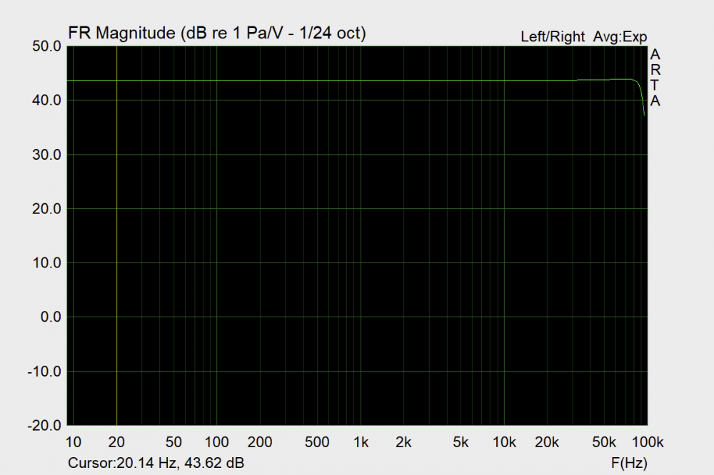
Similar to the loopback test you ran in SoundEasy, one neat thing I like to run in ARTA is a simple jig loopback test.
Connect the jig to your amp, but without a speaker connected. Connect both reference and impedance probes, however select "SPL", which effectively connects both probes to the amp output.
In ARTA, select FR1, then setup the measurement for 192kHz sample rate.
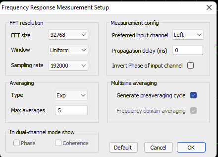
Another option I usually set here is to right click on the chart and set 1/12 octave smoothing.
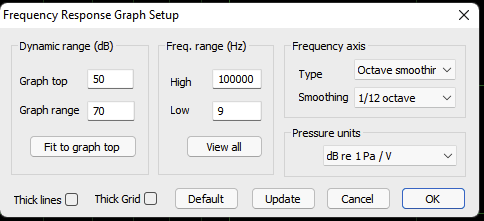
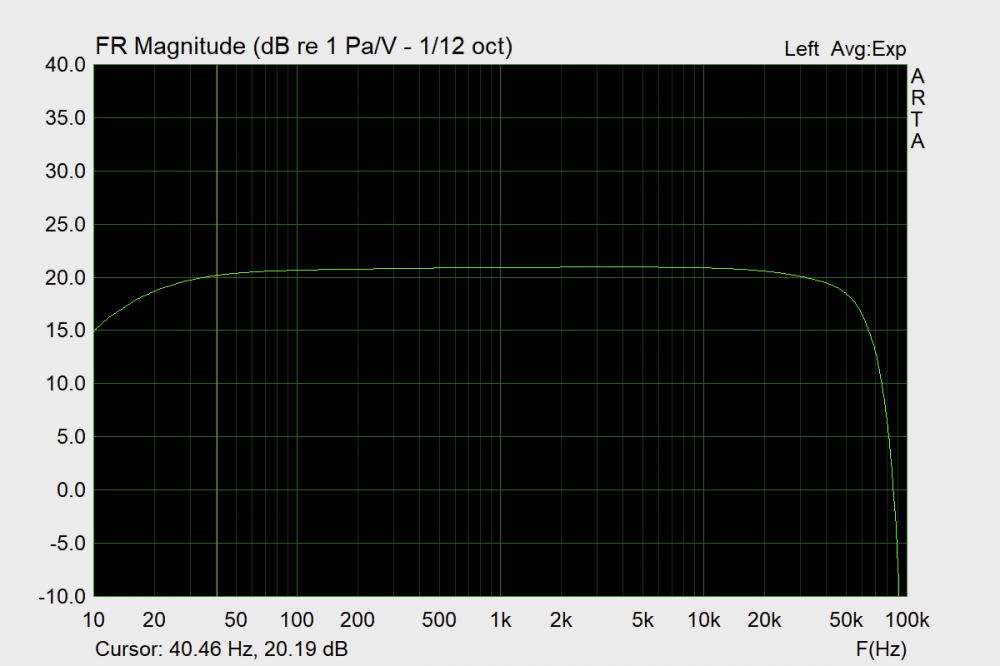
Input of left or right won't matter here, this is a single channel measurement and we've looped back both L and R channels. Then, select "PN Pink" under the generator dropdown, and push the red play button. Adjust the frequency range to show from 10Hz to 100kHz and you should be observing the frequency response of the chain from UR22 to amp and back through your probes. For this screenshot I used an "antique" Realistic SA-1000, more modern equipment will probably be a bit flatter at the lower frequencies.
You probably don't need to do this, but you can check both L and R input to verify that you get the same result with both probes, just to verify that there are no wiring mistakes.
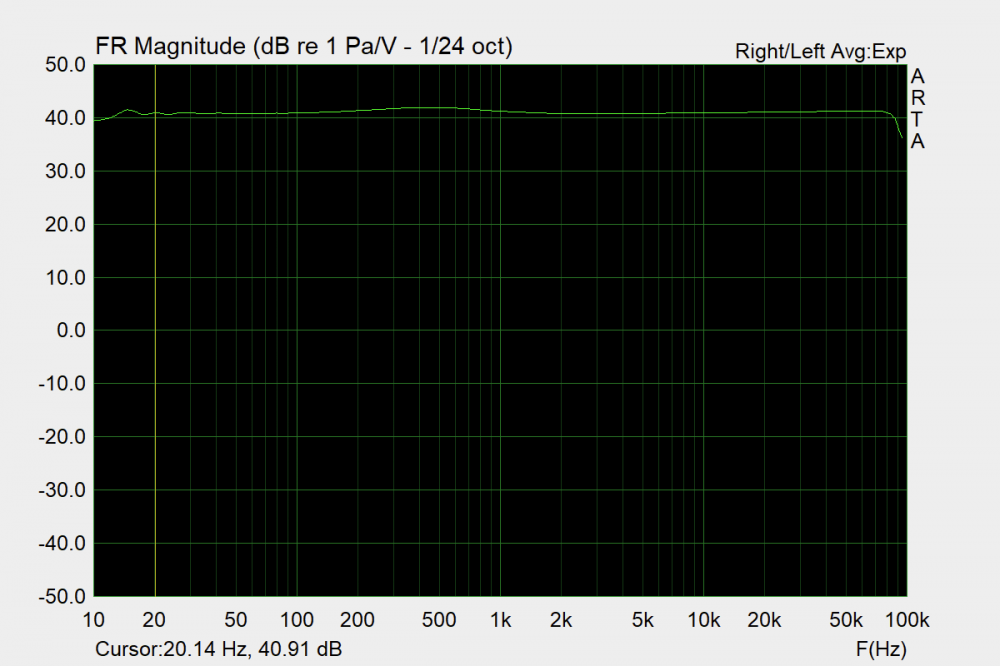
Next step demonstrates the wonders of a 2-channel measurement. Select FR2 and do the same thing. Here you should see a flat line, near 100kHz we have not enough signal to get a measurement. The frequency response of the equipment has been compensated for by normalizing one channel input to the other. Even though the measured frequency response is not completely linear, both inputs measure the same thing, so there is no difference, hence a flat line.
If you want to see how the transfer function of how the "protection cap" interacts with a driver, you can do the same with a driver connected and the high pass switch turned on.
The FR1 response will show you the transfer function of the capacitor inserted:
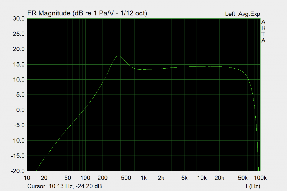
For a dome tweeter there is some peaking as you can expect with a single component filter (this was an XT25 in a waveguide). 50uF cap may be a bit much in retrospect, cutting that in half should be fine.
The FR2 response should still provide you with a relatively flat line. On my end I show a 1dB bump around 500Hz which is interesting, as the only real difference between the two probes is the inclusion of a switch, a couple inches of wire, and differences between the tolerance of the probe resistors. I'm not too concerned anyway, the normal use case for this measurement would be reference vs mic input, and for impedance measurement in LIMP, the probe tolerance is removed through the calibration process.
I've also just decided that an a receiver with speaker A/B selection is ideal for a setup at your desk. You can leave the receiver connected to your desk speakers on the A terminals for every day use, and leave the B connection to the jig, then just select the B speakers when you want to measure something. It also provides you the ability to disconnect the amp from the jig without turning it completely off.
Good stuff. Will give your Arta loopback test a try. Looks like I completely missed your 96kHz sample rate and lead compensation instructions for LIMP. I'll go back and make these changes. My mind was really "burned out" yesterday when I set this up because I had just spent several hours fighting with Soundeasy. I think I know what I was doing wrong, so I'm going to give that program another try later.
No problem, the lead calibration is generally making very small changes for driver measurements, but if you are measurig small resistances of inductors and want accurate DCR then I'd absolutely recommend going through the lead resistance compensation process.
FWIW the documentation for SE doesn't say this specifically, but you can run the calibration in SE in exactly the same manner as you do in ARTA. Just disconnect the load and hit the cal button. Make sure the gain of each input is set roughly the same, SE will complain if the 2 input channels have significant difference in level.
Updated my T/S measurement with LIMP document today with a bunch of screenshots.