@a4eaudio said:
So the whole purpose of the InDIYana them contest ("Tweeter Yoga") is to deal with the directivity of larger woofer and a tweeter limited in size
I'd argue that the whole purpose is to wow the crowd in 3-4 minutes
I have a good tweeter and can get down to 1.4 or even 1.2khz, but that is simply not enough.
This may sound counter-intuitive, but with 1.4kHz crossover point, try 300-340mm C-C between drivers.
Figures 2 and 3 show two different crossovers. Without saying anything else about the drivers or crossovers, what can you tell from Figure 2 vs Figure 3?
Figure 3 attempts a better overall power response by sacrificing a bit of on-axis response by the bump at 1.2kHz.
Could you also post the line chart for crossovers A and B? My eyes glaze over when trying to interpret polar map colors and contour lines. With the line chart, I can clearly see problem areas where the curves bunch together or crisscross back & forth. With the polar map, I have no idea what I am looking at.
@dcibel said:
I'd argue that the whole purpose is to wow the crowd in 3-4 minutes
I know you're not a fan. But as a beginner speaker builder, it is nice to have a challenge and a reason to build something that will teach me some things.
This may sound counter-intuitive, but with 1.4kHz crossover point, try 300-340mm C-C between drivers.
Speaker cabinet and driver layout is done at this point. This is a temporary build just for the theme and these drivers will get repurposed. I did use VituixCad's diffraction tool and purposely placed the tweeter to get a boost around 1.4khz as I knew I would crossover near there. I realize now (now that I'm trying to shape the roll-off) that that was not such a good idea.
Figure 3 attempts a better overall power response by sacrificing a bit of on-axis response by the bump at 1.2kHz.
Thanks. I thought about this a bit, and then flipped back and forth between the SPL, Power & DI, and Directivity screens many, many times to try to correlate the SPL and Power graphs, which I do understand, and the Heat Map and started to see some of the relationship that the heat map is illustrated.
@jhollander said:
I'd rather look at FR graphs, but x-o B looks smoother.
Yes, but I (mostly) understand what the FR and Power graphs are showing. The Directivity Heat Map is very popular, and I think pretty powerful, but not something I take advantage of since I don't really understand how to interpret it. This exercise helped me. I see some places I still need to try to improve, then I'll post the FR graphs and some more info.
@4thtry said:
Could you also post the line chart for crossovers A and B?
Sure, see below.
Just to be clear, this is not a final XO. I'm still working on it, but this was really to try to specifically understand the heat map better. The challenge of the theme is really forcing some tradeoffs and I'm just trying to weigh the pros and cons of different choices I can make. I have to admit that Dave Fred's (really) nice directivity curves that dcibel re-posted above made me pretty envious.
Thanks for the line graph. My eye is drawn to 2.2kHz, where the curves crisscross at 0 to 30 degrees. This shows up on the heat map as a small contour circle on crossover A. I would have to say that crossover B looks a little bit better in this regard. Since we are designing for an approximate 0-30 degree listening window, the crisscross area might cause the soundstage to collapse for some listeners that are 30 degrees off-axis with respect to one speaker and 0 degrees off-axis with respect to the other.
That is pretty interesting. Not sure how easy you could see it, because those 10, 20, and 30 degree lines are a poor color against the black background. Here are the same line graphs showing only 0 to 60 degrees with a white background.
I know you're not a fan. But as a beginner speaker builder, it is nice to have a challenge and a reason to build something that will teach me some things.
Same boat. I'm pretty green to this advanced stuff.
I'm also dealing with an off-axis hump, though for me it is right at crossover frequency. The knee on both drivers seems to not drop off as early so they sum up to the bump. Dunno if there is a baffle interaction causing on-axis cancellation or what. In listening to female voices, when they belt vowels it hits that "drive ya up the wall" note sometimes. So I suspect that is the hump I'm hearing. Sofar the only thing I can think to try is pull the "knees" farther apart and just deal with the on-axis slump.
@dcibel said:
I'd argue that the whole purpose is to wow the crowd in 3-4 minutes
I know you're not a fan. But as a beginner speaker builder, it is nice to have a challenge and a reason to build something that will teach me some things.
It's not that I'm not a fan, I think the challenges can be great fun, and quite educational as you mention. However I have limited free time and energy and don't want to spend that time building something that I wouldn't otherwise build for myself or I think is somehow flawed due to limitations of the challenge requirements. I'm also geologically located where it's not practical for me to participate in these challenges anyway, so I just treat every speaker as a challenge
This may sound counter-intuitive, but with 1.4kHz crossover point, try 300-340mm C-C between drivers.
Speaker cabinet and driver layout is done at this point. This is a temporary build just for the theme and these drivers will get repurposed. I did use VituixCad's diffraction tool and purposely placed the tweeter to get a boost around 1.4khz as I knew I would crossover near there. I realize now (now that I'm trying to shape the roll-off) that that was not such a good idea.
The purpose of the driver C-C is not strictly diffraction related, but balancing crossover frequency with power response. Kimmo has provided some great insight in the past, that for flat faceplate tweeters and standard LR4 filters, ideal C-C distance generally ends up at 1.2 to 1.4x the crossover frequency. Of course, you don't have to rebuild your baffle to see the effects of changing C-C driver distance. Just hover your mouse cursor over woofer Y axis value and scroll.
Under auxiliary menu you'll find a wave length calculator that will calculate 1.2x frequency for you.
I know you're not a fan. But as a beginner speaker builder, it is nice to have a challenge and a reason to build something that will teach me some things.
Same boat. I'm pretty green to this advanced stuff.
I'm also dealing with an off-axis hump, though for me it is right at crossover frequency. The knee on both drivers seems to not drop off as early so they sum up to the bump. Dunno if there is a baffle interaction causing on-axis cancellation or what. In listening to female voices, when they belt vowels it hits that "drive ya up the wall" note sometimes. So I suspect that is the hump I'm hearing. Sofar the only thing I can think to try is pull the "knees" farther apart and just deal with the on-axis slump.
I think one of the things that may cause this type of on-axis slump is the fact that, when you are directly on axis to a centrally positioned tweeter, the diffraction cancellation effect doubles and causes an on-axis dip. If you move slightly off-axis, the dip starts going away because the tweeter is no longer centrally positioned with respect to the microphone. This is why some builders offset the tweeter slightly. Another solution is to boost the size of roundovers (going from 0.75" radius up to 2.5" radius).
In your case, however, it sounds like the bump is lower in frequency. Does the bump follow evenly along, both on and off-axis?
I know you're not a fan. But as a beginner speaker builder, it is nice to have a challenge and a reason to build something that will teach me some things.
Same boat. I'm pretty green to this advanced stuff.
I'm also dealing with an off-axis hump, though for me it is right at crossover frequency. The knee on both drivers seems to not drop off as early so they sum up to the bump. Dunno if there is a baffle interaction causing on-axis cancellation or what. In listening to female voices, when they belt vowels it hits that "drive ya up the wall" note sometimes. So I suspect that is the hump I'm hearing. Sofar the only thing I can think to try is pull the "knees" farther apart and just deal with the on-axis slump.
Try modifying one slope either tweeter or woofer, by doing so, will change the phase and the summation.
They seemed to sum up nicely and reversing polarity gave what seemed like a good inverse peak suckout. I did try messing around with values one at a time to see what would change. The best I could manage at the time was to reduce the lowpass frequency a bit while staying in-phase, causing a dip on-axis to try and flatten the off-axis better.
I typically measure with the mic roughly centered between the drivers. I tried dropping it down to woofer center too but didn't realy make any breakthroughs. Don't remember which measurements were those though. I take so many and only end up documenting things that seem to work. By this point I probably need to get more off-axis measurements before I go wasting more of everyone's time.
They have 30 and 60deg off axis measurements as a rough guide. The dip around 2.9khz I suspect is where it hands off to the whizzer as the phase drops off a cliff until settling to the new value. So I don't know that I want to raise the crossover a whole bunch. But if I have the parts on hand to do it, It wont hurt to try.
Other info I have on hand...
Driver C-C is near exactly 6.5".
Baffle 13.25"x18" with 1/2" radius all around. Drivers visually centered, not crowding the top or bottom. But due to 8" woofer that puts the tweeter within the top third. Tweeter center is approximately 4 9/16" from the top.
If ya think I've dug myself a hole, it is fine to tell me. I don't really have an ego to defend and drivers can go elsewhere after indiyana. I'm in it to learn.
If ya think I've dug myself a hole, it is fine to tell me. I don't really have an ego to defend and drivers can go elsewhere after indiyana. I'm in it to learn.
Don't give up, you'll learn way more beating this into submission than you would if it was an easy build.
None of the builds I have done were particularly easy for me. Seems I usually find out something new each time that totally turns my brain sideways and have to relearn alot of previous assumptions. An easy one would be nice by this point. At least to confirm I haven't relearned everything wrong.
Dorked around with one speaker to try out some more things in quick succession and think I may have stumbled on something. Still technically has issues, but it doesn't drive me out of the room and actually sounds pretty "fun". Just need to verify in stereo. Hopefully tomorrow so I can button this up over the weekend.
@DrewsBrews said:
Seems I usually find out something new each time that totally turns my brain sideways and have to relearn a lot of previous assumptions.
Quoted for truth... This is what keeps the audio design hobby so interesting.
Thanks to all for the comments so far. Early posts were preliminary simulations and trying to better understand certain things. Here is what I have come up. I had tried several more complicated crossover layouts and this relatively simple one kind of fell into my lap. Do you see anything obvious that needs to be fixed?
My checklist:
On-axis is pretty smooth (pretty close to +/- 1db from 55Hz to 10Khz). Slight dip between 2khz and 6khz. Not a deliberate BBC dip or anything, just a result of the drivers and better than a hump in that region.
Listening window target -0.15db/oct .
In-room Response target -0.8db/oct
Early rReflections and Directivity Index. Not great, but it doesn't seem there is much more I can do given my woofer off-axis response.
Phase alignment is good
Impedance. Minimum impedance is 3.9ohms at 150Hz. I don't know whether impedance phase is good or not but it doesn't look out-of-the-ordinary to me.
If the bass balance is enough and sounds full, then you have a plausible solution, IMO. IF NOT, the plot looks like it might need to go to 2.0mH on the woofer.
Impedance phase is fine. Keep it between +/-30°, and at worst is -45°, so even +/-40° is okay. Even then, if the impedance is not low at the same point, then the load is likely just fine.
Hard for me to tell at this scale but the FR is not flat enough from 2.5K to 6K imo and the splice at 250 hz looks off. As Wolf said maybe take a look at raw and see if you're getting 6 dB baffle step from your x-o.
To be completely honest, the rising response of the tweeter from the xover point and having the woofer still relatively at nominal amplitude rolling off steeply is how I was able to get the Zingers to sing without having the directivity peak at transition. It seems to work rather well. Without the waveguide, this seems to work. It's a delicate balance to get the mids right, but it can be done.
@jhollander said:
Hard for me to tell at this scale but the FR is not flat enough from 2.5K to 6K imo ...
@Wolf said:
To be completely honest, the rising response of the tweeter from the xover point and having the woofer still relatively at nominal amplitude rolling off steeply is how I was able to get the Zingers to sing without having the directivity peak at transition...
I'm working on tweaks. I think I may end up with 1.8mh on the woofer rather than the full 2.0mh.
I think wolf nailed the tradeoff I'm fighting with. I can make the FR flatter, but my In-Room response suffers. VituixCAD has an optimization option with 50% listening window and 50% in-room response. I'd say I'm working subjectively with 33% on-axis, 33% listening window and 33% in-room response.
@DrewsBrews said:
Yep. I ended up with a V shape on-axis response that bottoms out around 1.8k.
On the bright side...in my frustration I went to AudioScienceReview (ASR) to look at what some "good" polar responses look like...since they LOVE their graphs and charts over there. I found several speakers, that while getting picked apart for all the "flaws" in the graphs, did well in the subjective "actually sounds good" portion of the review. Most of those "flawed" two-ways look like a lot of the polar responses that I'm getting in VituixCAD. My theme speaker is actually flawed in exactly the ways the challenge is supposed to present a challenge.
Comments
I'd argue that the whole purpose is to wow the crowd in 3-4 minutes")
This may sound counter-intuitive, but with 1.4kHz crossover point, try 300-340mm C-C between drivers.
Figure 3 attempts a better overall power response by sacrificing a bit of on-axis response by the bump at 1.2kHz.
I'd rather look at FR graphs, but x-o B looks smoother.
I am in agreement with Reid and John.
InDIYana Event Website
Could you also post the line chart for crossovers A and B? My eyes glaze over when trying to interpret polar map colors and contour lines. With the line chart, I can clearly see problem areas where the curves bunch together or crisscross back & forth. With the polar map, I have no idea what I am looking at.
I know you're not a fan. But as a beginner speaker builder, it is nice to have a challenge and a reason to build something that will teach me some things.
Speaker cabinet and driver layout is done at this point. This is a temporary build just for the theme and these drivers will get repurposed. I did use VituixCad's diffraction tool and purposely placed the tweeter to get a boost around 1.4khz as I knew I would crossover near there. I realize now (now that I'm trying to shape the roll-off) that that was not such a good idea.
Thanks. I thought about this a bit, and then flipped back and forth between the SPL, Power & DI, and Directivity screens many, many times to try to correlate the SPL and Power graphs, which I do understand, and the Heat Map and started to see some of the relationship that the heat map is illustrated.
Yes, but I (mostly) understand what the FR and Power graphs are showing. The Directivity Heat Map is very popular, and I think pretty powerful, but not something I take advantage of since I don't really understand how to interpret it. This exercise helped me. I see some places I still need to try to improve, then I'll post the FR graphs and some more info.
Sure, see below.
Just to be clear, this is not a final XO. I'm still working on it, but this was really to try to specifically understand the heat map better. The challenge of the theme is really forcing some tradeoffs and I'm just trying to weigh the pros and cons of different choices I can make. I have to admit that Dave Fred's (really) nice directivity curves that dcibel re-posted above made me pretty envious.
Figure 1.2 (XO A line curve)
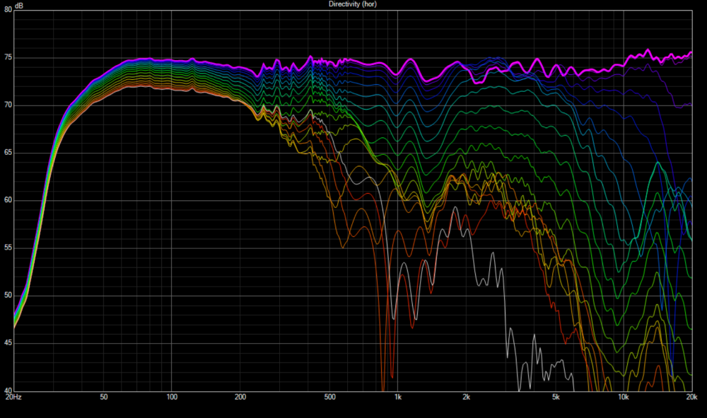
Figure 2.2 (XO B line curve)
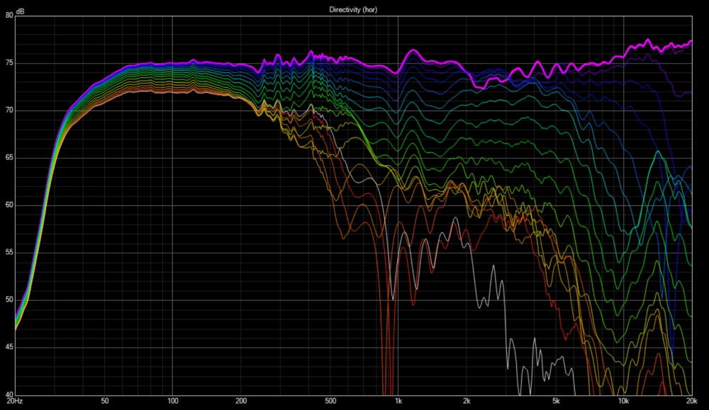
Thanks for the line graph. My eye is drawn to 2.2kHz, where the curves crisscross at 0 to 30 degrees. This shows up on the heat map as a small contour circle on crossover A. I would have to say that crossover B looks a little bit better in this regard. Since we are designing for an approximate 0-30 degree listening window, the crisscross area might cause the soundstage to collapse for some listeners that are 30 degrees off-axis with respect to one speaker and 0 degrees off-axis with respect to the other.
That is pretty interesting. Not sure how easy you could see it, because those 10, 20, and 30 degree lines are a poor color against the black background. Here are the same line graphs showing only 0 to 60 degrees with a white background.
Same boat. I'm pretty green to this advanced stuff.
I'm also dealing with an off-axis hump, though for me it is right at crossover frequency. The knee on both drivers seems to not drop off as early so they sum up to the bump. Dunno if there is a baffle interaction causing on-axis cancellation or what. In listening to female voices, when they belt vowels it hits that "drive ya up the wall" note sometimes. So I suspect that is the hump I'm hearing. Sofar the only thing I can think to try is pull the "knees" farther apart and just deal with the on-axis slump.
It's not that I'm not a fan, I think the challenges can be great fun, and quite educational as you mention. However I have limited free time and energy and don't want to spend that time building something that I wouldn't otherwise build for myself or I think is somehow flawed due to limitations of the challenge requirements. I'm also geologically located where it's not practical for me to participate in these challenges anyway, so I just treat every speaker as a challenge")
The purpose of the driver C-C is not strictly diffraction related, but balancing crossover frequency with power response. Kimmo has provided some great insight in the past, that for flat faceplate tweeters and standard LR4 filters, ideal C-C distance generally ends up at 1.2 to 1.4x the crossover frequency. Of course, you don't have to rebuild your baffle to see the effects of changing C-C driver distance. Just hover your mouse cursor over woofer Y axis value and scroll.
Under auxiliary menu you'll find a wave length calculator that will calculate 1.2x frequency for you.
I think one of the things that may cause this type of on-axis slump is the fact that, when you are directly on axis to a centrally positioned tweeter, the diffraction cancellation effect doubles and causes an on-axis dip. If you move slightly off-axis, the dip starts going away because the tweeter is no longer centrally positioned with respect to the microphone. This is why some builders offset the tweeter slightly. Another solution is to boost the size of roundovers (going from 0.75" radius up to 2.5" radius).
In your case, however, it sounds like the bump is lower in frequency. Does the bump follow evenly along, both on and off-axis?
Try modifying one slope either tweeter or woofer, by doing so, will change the phase and the summation.
They seemed to sum up nicely and reversing polarity gave what seemed like a good inverse peak suckout. I did try messing around with values one at a time to see what would change. The best I could manage at the time was to reduce the lowpass frequency a bit while staying in-phase, causing a dip on-axis to try and flatten the off-axis better.
I'll give it another shot.
Can you post a pic of your reverse null?
Off axis bump

I typically measure with the mic roughly centered between the drivers. I tried dropping it down to woofer center too but didn't realy make any breakthroughs. Don't remember which measurements were those though. I take so many and only end up documenting things that seem to work. By this point I probably need to get more off-axis measurements before I go wasting more of everyone's time.
In this case an off-axis hump means you're probably crossing a bit too high- it's a a bit counter-intuitive. But here's why-
You mid(woofer) is still has lot of energy off axis at the crossover frequency, and the tweeter is has excellent dispersion at this low frequency.
If you move your crossover closer to 2.5KHz - 3KHz. you will find the off axis a bit better.
I think you mean low.
So there are a few things to balance that can optimize overall power & DI chart.
Using the SB 8" fullrange https://madisoundspeakerstore.com/approx-8-fullrange/sb-acoustics-sb20frpc30-8-8-paper-full-range/
They have 30 and 60deg off axis measurements as a rough guide. The dip around 2.9khz I suspect is where it hands off to the whizzer as the phase drops off a cliff until settling to the new value. So I don't know that I want to raise the crossover a whole bunch. But if I have the parts on hand to do it, It wont hurt to try.
Other info I have on hand...
Driver C-C is near exactly 6.5".
Baffle 13.25"x18" with 1/2" radius all around. Drivers visually centered, not crowding the top or bottom. But due to 8" woofer that puts the tweeter within the top third. Tweeter center is approximately 4 9/16" from the top.
If ya think I've dug myself a hole, it is fine to tell me. I don't really have an ego to defend and drivers can go elsewhere after indiyana. I'm in it to learn.
I think most have touched on this here, but force a low order crossover slope then check your off axis results.
Don't give up, you'll learn way more beating this into submission than you would if it was an easy build.
None of the builds I have done were particularly easy for me. Seems I usually find out something new each time that totally turns my brain sideways and have to relearn alot of previous assumptions. An easy one would be nice by this point.") At least to confirm I haven't relearned everything wrong.
At least to confirm I haven't relearned everything wrong.
Dorked around with one speaker to try out some more things in quick succession and think I may have stumbled on something. Still technically has issues, but it doesn't drive me out of the room and actually sounds pretty "fun". Just need to verify in stereo. Hopefully tomorrow so I can button this up over the weekend.
Quoted for truth... This is what keeps the audio design hobby so interesting.
Thanks to all for the comments so far. Early posts were preliminary simulations and trying to better understand certain things. Here is what I have come up. I had tried several more complicated crossover layouts and this relatively simple one kind of fell into my lap. Do you see anything obvious that needs to be fixed?
My checklist:
If the bass balance is enough and sounds full, then you have a plausible solution, IMO. IF NOT, the plot looks like it might need to go to 2.0mH on the woofer.
Impedance phase is fine. Keep it between +/-30°, and at worst is -45°, so even +/-40° is okay. Even then, if the impedance is not low at the same point, then the load is likely just fine.
InDIYana Event Website
Hard for me to tell at this scale but the FR is not flat enough from 2.5K to 6K imo and the splice at 250 hz looks off. As Wolf said maybe take a look at raw and see if you're getting 6 dB baffle step from your x-o.
To be completely honest, the rising response of the tweeter from the xover point and having the woofer still relatively at nominal amplitude rolling off steeply is how I was able to get the Zingers to sing without having the directivity peak at transition. It seems to work rather well. Without the waveguide, this seems to work. It's a delicate balance to get the mids right, but it can be done.
InDIYana Event Website
I'm working on tweaks. I think I may end up with 1.8mh on the woofer rather than the full 2.0mh.
I think wolf nailed the tradeoff I'm fighting with. I can make the FR flatter, but my In-Room response suffers. VituixCAD has an optimization option with 50% listening window and 50% in-room response. I'd say I'm working subjectively with 33% on-axis, 33% listening window and 33% in-room response.
Yep. I ended up with a V shape on-axis response that bottoms out around 1.8k.
On the bright side...in my frustration I went to AudioScienceReview (ASR) to look at what some "good" polar responses look like...since they LOVE their graphs and charts over there. I found several speakers, that while getting picked apart for all the "flaws" in the graphs, did well in the subjective "actually sounds good" portion of the review. Most of those "flawed" two-ways look like a lot of the polar responses that I'm getting in VituixCAD. My theme speaker is actually flawed in exactly the ways the challenge is supposed to present a challenge.